Recent from talks
Volute spring
Knowledge base stats:
Talk channels stats:
Members stats:
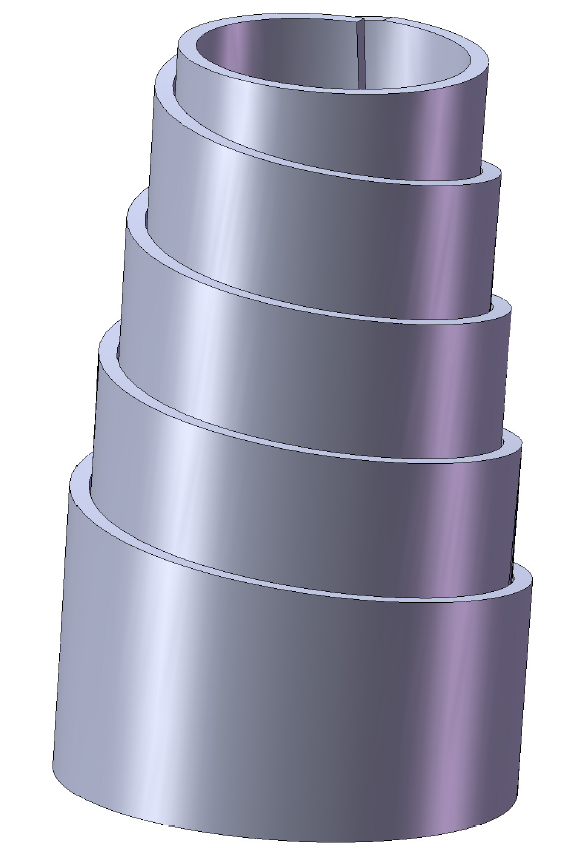
Volute spring
A volute spring, also known as a conical spring, is a compression spring in the form of a cone (somewhat like the classical volute decorative architectural ornament). Under compression, the coils slide past each other, thus enabling the spring to be compressed to a very short length in comparison with what would be possible with a more conventional helical spring.
There are two typical types of volute spring:
Double volute springs can frequently be found as a component of garden pruning shears. Short posts anchored in each side of the handles, and inserted into each narrow end of the spring, keep the spring in position.
However, the applications of volute springs are not limited to such light-duty purposes as gardening shears. For example, volute springs are used to cushion the impact between railway cars and as a core element of the suspension system of Sherman tanks. A volute spring buffer device for railway cars was invented by John Brown in 1848.
Hub AI
Volute spring AI simulator
(@Volute spring_simulator)
Volute spring
A volute spring, also known as a conical spring, is a compression spring in the form of a cone (somewhat like the classical volute decorative architectural ornament). Under compression, the coils slide past each other, thus enabling the spring to be compressed to a very short length in comparison with what would be possible with a more conventional helical spring.
There are two typical types of volute spring:
Double volute springs can frequently be found as a component of garden pruning shears. Short posts anchored in each side of the handles, and inserted into each narrow end of the spring, keep the spring in position.
However, the applications of volute springs are not limited to such light-duty purposes as gardening shears. For example, volute springs are used to cushion the impact between railway cars and as a core element of the suspension system of Sherman tanks. A volute spring buffer device for railway cars was invented by John Brown in 1848.
Recent media