Ohm
Ohm
Main page
1823037

Ohm

logo
Community Hub0 subscribers
Read side by side
from Wikipedia

ohm
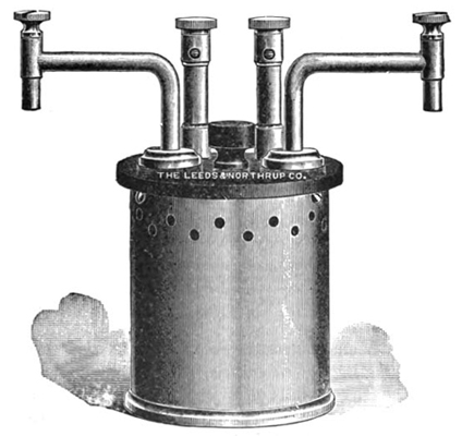
A laboratory one-ohm standard resistor, c. 1917
General information
Unit systemSI
Unit ofelectrical resistance
SymbolΩ
Named afterGeorg Ohm
Conversions
1 Ω in ...... is equal to ...
   SI base units   kgm2s−3A−2

The ohm (symbol: Ω, the uppercase Greek letter omega) is the unit of electrical resistance in the International System of Units (SI). It is named after German physicist Georg Ohm (1789–1854). Various empirically derived standard units for electrical resistance were developed in connection with early telegraphy practice, and the British Association for the Advancement of Science proposed a unit derived from existing units of mass, length and time, and of a convenient scale for practical work as early as 1861.

Following the 2019 revision of the SI, in which the ampere and the kilogram were redefined in terms of fundamental constants, the ohm is now also defined as an exact value in terms of these constants.

Definition

[edit]

The ohm is defined as an electrical resistance between two points of a conductor when a constant potential difference of one volt (V), applied to these points, produces in the conductor a current of one ampere (A), the conductor not being the seat of any electromotive force.[1]

In which the following additional units appear: siemens (S), watt (W), second (s), farad (F), henry (H), weber (Wb), joule (J), coulomb (C), kilogram (kg), and meter (m).

In many cases the resistance of a conductor is approximately constant within a certain range of voltages, temperatures, and other parameters. These are called linear resistors. In other cases resistance varies, such as in the case of the thermistor, which exhibits a strong dependence of its resistance with temperature.

In the US, a double vowel in the prefixed units "kiloohm" and "megaohm" is commonly simplified, producing "kilohm" and "megohm".[2][3][4][5]

One of the functions of many types of multimeters is the measurement of resistance in ohms.

In alternating current circuits, electrical impedance is also measured in ohms.

Relation to conductance

[edit]

The siemens (S) is the SI derived unit of electric conductance and admittance, historically known as the "mho" (ohm spelled backwards, symbol is ℧); it is one reciprocal ohm: 1 S = 1 Ω−1.

Power as a function of resistance

[edit]

The power dissipated by a resistor may be calculated from its resistance, and the voltage or current involved. The formula is a combination of Ohm's law and Joule's law:
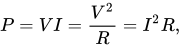
where P is the power, R is the resistance, V is the voltage across the resistor, and I is the current through the resistor.

A linear resistor has a constant resistance value over all applied voltages or currents; many practical resistors are linear over a useful range of currents. Non-linear resistors have a value that may vary depending on the applied voltage (or current). Where alternating current is applied to the circuit (or where the resistance value is a function of time), the relation above is true at any instant, but calculation of average power over an interval of time requires integration of "instantaneous" power over that interval.

Since the ohm belongs to a coherent system of units, when each of these quantities has its corresponding SI unit (watt for P, ohm for R, volt for V and ampere for I, which are related as in § Definition) this formula remains valid numerically when these units are used (and thought of as being cancelled or omitted).

History

[edit]

The rapid rise of electrotechnology in the last half of the 19th century created a demand for a rational, coherent, consistent, and international system of units for electrical quantities. Telegraphers and other early users of electricity in the 19th century needed a practical standard unit of measurement for resistance. Resistance was often expressed as a multiple of the resistance of a standard length of telegraph wires; different agencies used different bases for a standard, so units were not readily interchangeable. Electrical units so defined were not a coherent system with the units for energy, mass, length, and time, requiring conversion factors to be used in calculations relating energy or power to resistance.[6]

Two different methods of establishing a system of electrical units can be chosen. Various artifacts, such as a length of wire or a standard electrochemical cell, could be specified as producing defined quantities for resistance, voltage, and so on. Alternatively, the electrical units can be related to the mechanical units by defining, for example, a unit of current that gives a specified force between two wires, or a unit of charge that gives a unit of force between two unit charges. This latter method ensures coherence with the units of energy. Defining a unit for resistance that is coherent with units of energy and time in effect also requires defining units for potential and current. It is desirable that one unit of electrical potential will force one unit of electric current through one unit of electrical resistance, doing one unit of work in one unit of time, otherwise, all electrical calculations will require conversion factors.

Since so-called "absolute" units of charge and current are expressed as combinations of units of mass, length, and time, dimensional analysis of the relations between potential, current, and resistance show that resistance is expressed in units of length per time – a velocity. Some early definitions of a unit of resistance, for example, defined a unit resistance as one quadrant of the Earth per second.

The absolute-unit system related magnetic and electrostatic quantities to metric base units of mass, time, and length. These units had the great advantage of simplifying the equations used in the solution of electromagnetic problems, and eliminated conversion factors in calculations about electrical quantities. However, the centimeter–gram–second, CGS, units turned out to have impractical sizes for practical measurements.

Various artifact standards were proposed as the definition of the unit of resistance. In 1860 Werner Siemens (1816–1892) published a suggestion for a reproducible resistance standard in Poggendorff's Annalen der Physik und Chemie.[7] He proposed a column of pure mercury, of one square millimeter cross section, one meter long: Siemens mercury unit. However, this unit was not coherent with other units. One proposal was to devise a unit based on a mercury column that would be coherent – in effect, adjusting the length to make the resistance one ohm. Not all users of units had the resources to carry out metrology experiments to the required precision, so working standards notionally based on the physical definition were required.

In 1861, Latimer Clark (1822–1898) and Sir Charles Bright (1832–1888) presented a paper at the British Association for the Advancement of Science meeting [8] suggesting that standards for electrical units be established and suggesting names for these units derived from eminent philosophers, 'Ohma', 'Farad' and 'Volt'. The BAAS in 1861 appointed a committee including Maxwell and Thomson to report upon standards of electrical resistance.[9] Their objectives were to devise a unit that was of convenient size, part of a complete system for electrical measurements, coherent with the units for energy, stable, reproducible and based on the French metrical system.[10] In the third report of the committee, 1864, the resistance unit is referred to as "B.A. unit, or Ohmad".[11] By 1867 the unit is referred to as simply ohm.[12]

The B.A. ohm was intended to be 109 CGS units but owing to an error in calculations the definition was 1.3% too small. The error was significant for preparation of working standards.

On 21 September 1881 the International Electrical Congress defined a practical unit of ohm for the resistance, based on CGS units, using a mercury column 1 mm2 in cross-section, approximately 104.9 cm in length at 0 °C, similar to the apparatus suggested by Siemens.

A legal ohm, a reproducible standard, was defined by the international conference of electricians at Paris in 1884 as the resistance of a mercury column of specified weight and 106 cm long; this was a compromise value between the B. A. unit (equivalent to 104.7 cm), the Siemens unit (100 cm by definition), and the CGS unit.[13] Although called "legal", this standard was not adopted by any national legislation. The "international" ohm was recommended by unanimous resolution at the International Electrical Congress 1893 in Chicago.[14] The unit was based upon the ohm equal to 109 units of resistance of the C.G.S. system of electromagnetic units. The international ohm is represented by the resistance offered to an unvarying electric current in a mercury column of constant cross-sectional area 106.3 cm long of mass 14.4521 grams and 0 °C. This definition became the basis for the legal definition of the ohm in several countries. In 1908, this definition was adopted by scientific representatives from several countries at the International Conference on Electric Units and Standards in London.[14] The mercury column standard was maintained until the 1948 General Conference on Weights and Measures, at which the ohm was redefined in absolute terms instead of as an artifact standard.

By the end of the 19th century, units were well understood and consistent. Definitions would change with little effect on commercial uses of the units. Advances in metrology allowed definitions to be formulated with a high degree of precision and repeatability.

Historical units of resistance

[edit]
Unit[15] Definition Value in B.A. ohms Remarks
Absolute foot/second × 107 using imperial units 0.3048 considered obsolete even in 1884
Thomson's unit using imperial units 0.3202 100 million ft/s (30,480 km/s), considered obsolete even in 1884
Jacobi copper unit A specified copper wire 25 ft (7.620 m) long weighing 345 gr (22.36 g) 0.6367 Used in 1850s
Weber's absolute unit × 107 Based on the meter and the second 0.9191
Siemens mercury unit 1860. A column of pure mercury 0.9537 100 cm and 1 mm2 cross section at 0 °C
British Association (B.A.) "ohm" 1863 1.000 Standard coils deposited at Kew Observatory in 1863[16]
Digney, Breguet, Swiss 9.266–10.420 Iron wire 1 km long and 4 mm2 cross section
Matthiessen 13.59 1 mi (1.609 km) of 116-inch-diameter (1.588 mm) pure annealed copper wire at 15.5 °C
Varley 25.61 One mile of special 116-inch-diameter copper wire
German mile 57.44 A German mile (8,238 yd or 7,533 m) of iron wire 16 in (4.233 mm) diameter
Abohm 10−9 Electromagnetic absolute unit in centimeter–gram–second units
Statohm 8.987551787×10¹¹ Electrostatic absolute unit in centimeter–gram–second units

Realization of standards

[edit]

The mercury column method of realizing a physical standard ohm turned out to be difficult to reproduce, owing to the effects of non-constant cross section of the glass tubing. Various resistance coils were constructed by the British Association and others, to serve as physical artifact standards for the unit of resistance. The long-term stability and reproducibility of these artifacts was an ongoing field of research, as the effects of temperature, air pressure, humidity, and time on the standards were detected and analyzed.

Artifact standards are still used, but metrology experiments relating accurately dimensioned inductors and capacitors provided a more fundamental basis for the definition of the ohm. Since 1990 the quantum Hall effect has been used to define the ohm with high precision and repeatability. The quantum Hall experiments are used to check the stability of working standards that have convenient values for comparison.[17]

Following the 2019 revision of the SI, in which the ampere and the kilogram were redefined in terms of fundamental constants, the ohm is now also defined in terms of these constants.

Symbol

[edit]

The symbol Ω was suggested, because of the similar sound of ohm and omega, by William Henry Preece in 1867.[18] In documents printed before the Second World War the unit symbol often consisted of the raised lowercase omega (ω), such that 56 Ω was written as 56ω.

Historically, some document editing software applications have used the Symbol typeface to render the character Ω.[19] Where the font is not supported, the same document may be displayed with a "W" ("10 W" instead of "10 Ω", for instance). As W represents the watt, the SI unit of power, this can lead to confusion, making the use of the correct Unicode code point preferable.

Where the character set is limited to ASCII, the IEEE 260.1 standard recommends using the unit name "ohm" as a symbol instead of Ω.

In the electronics industry it is common to use the character R instead of the Ω symbol, thus, a 10 Ω resistor may be represented as 10R. This is part of the RKM code. It is used in many instances where the value has a decimal place. For example, 5.6 Ω is listed as 5R6, or 2200 Ω is listed as 2K2. This method avoids overlooking the decimal point, which may not be rendered reliably on components or when duplicating documents.

Unicode encodes the symbol as U+2126 OHM SIGN, distinct from Greek omega among letterlike symbols, but it is only included for backward compatibility and the Greek uppercase omega character U+03A9 Ω GREEK CAPITAL LETTER OMEGA (Ω, Ω) is preferred.[20] In MS-DOS and Microsoft Windows, the alt code ALT 234 may produce the Ω symbol. In Mac OS, ⌥ Opt+Z does the same.

See also

[edit]

Notes and references

[edit]
[edit]
Revisions and contributorsEdit on WikipediaRead on Wikipedia
from Grokipedia
Georg Simon Ohm (16 March 1789 – 6 July 1854) was a German physicist and mathematician renowned for discovering Ohm's law, which quantifies the direct proportionality between electric current and voltage in a conductor, with resistance as the constant of proportionality, expressed as $ V = IR $, where $ V $ is voltage in volts, $ I $ is current in amperes, and $ R $ is resistance in ohms.[1][2][3] Born in Erlangen, Bavaria (now Germany), to a locksmith father who provided his early education emphasizing mathematics and physics, Ohm attended the Erlangen Gymnasium before briefly studying at the University of Erlangen, from which he earned a doctorate in 1811.[1][4] Throughout his career, Ohm faced financial hardships and held various teaching positions, including in Switzerland, Bamberg, Cologne, and as a lecturer at the University of Erlangen, before being appointed professor of physics at the University of Munich in 1849, shortly before his death.[1] His seminal 1827 publication, Die galvanische Kette, mathematisch bearbeitet, detailed experimental work using a thermocouple and galvanometer to establish the principles of current flow in circuits, though it received initial criticism and limited recognition during his lifetime.[1][5] Later honors included the Copley Medal from the Royal Society in 1841 and election as a foreign member in 1842, affirming his foundational contributions to electrical theory.[1] The ohm (Ω), defined as the electrical resistance between two points of a conductor when a constant potential difference of one volt produces a current of one ampere, was adopted as the SI unit in his honor by the International Electrical Congress in 1881 and remains central to electrical engineering and physics.[3][6]

Definition and Units

Definition of the Ohm

Electrical resistance is a measure of the opposition that a material or device presents to the flow of electric current, arising from the interaction of charge carriers with the atomic lattice or impurities in the conductor. This opposition quantifies how much a given potential difference is required to drive a specific current through the material, without implying a linear proportionality at this stage. The ohm (symbol: Ω) is the derived unit of electrical resistance in the International System of Units (SI), defined as the resistance between two points of a conductor when a constant potential difference of 1 volt (V) applied across those points produces in the conductor a constant current of 1 ampere (A). This definition establishes the ohm as a unit of impedance to direct current (DC) flow, applicable to resistors and other components where current is steady-state. In terms of base SI units, the dimensional formula for resistance [R] is expressed as V/A, which expands to kg·m²·s⁻³·A⁻², where kg denotes kilograms (mass), m denotes meters (length), s denotes seconds (time), and A denotes amperes (electric current). This breakdown reflects the ohm's derivation from the definitions of volt (kg·m²·s⁻³·A⁻¹) and ampere, underscoring its composite nature in the SI framework. The ohm is equivalently 1 V/A by direct unit cancellation. For practical scaling, common multiples include the kiloohm (kΩ = 10³ Ω) used for higher resistances in circuits, such as in consumer electronics. In the centimeter-gram-second (CGS) electrostatic system, 1 Ω ≈ 1.11 × 10^{-12} statΩ, facilitating comparisons in older literature or specialized fields like high-voltage physics.[7]

Relation to Conductance

Conductance $ G $, denoted in siemens (S), quantifies the ease with which electric current flows through a material or component and is defined as the reciprocal of electrical resistance $ R $, expressed by the equation $ G = \frac{1}{R} $.[8] This inverse relationship highlights that higher resistance corresponds to lower conductance, and vice versa, providing a complementary measure to resistance in analyzing electrical circuits.[8] The International System of Units (SI) designates the siemens (symbol: S) as the unit for conductance, where 1 S equals the reciprocal of 1 ohm (Ω), or equivalently 1 ampere per volt (A/V).[8] In terms of base SI units, the dimensional formula for conductance is $ [G] = \mathrm{A}^2 \cdot \mathrm{s}^3 \cdot \mathrm{kg}^{-1} \cdot \mathrm{m}^{-2} $.[8] For example, a resistor with 1 Ω resistance exhibits a conductance of 1 S, while high-resistance materials, such as those used in insulators with resistances on the order of megohms, typically have conductances in the microsiemens (μS) range.[9] The name "siemens" honors Ernst Werner von Siemens, a 19th-century German inventor and industrialist, as established by the General Conference on Weights and Measures (CGPM) in 1971.[8]

Mathematical Relations

Power Dissipation in Resistors

The power dissipated in a resistor represents the rate at which electrical energy is transferred and converted into thermal energy within the device. To derive this, consider the work done on a small charge dqdq moving across a potential difference VV: the energy delivered is dU=VdqdU = V \, dq. The current II through the resistor is the rate of charge flow, I=dq/dtI = dq/dt, so the power PP, or energy per unit time, is P=dU/dt=VIP = dU/dt = V I.[10] Substituting the relation V=IRV = I R yields P=I2RP = I^2 R, or equivalently, P=V2/RP = V^2 / R./Book%3A_University_Physics_II_-Thermodynamics_Electricity_and_Magnetism(OpenStax)/10%3A_Direct-Current_Circuits/10.04%3A_Electrical_Energy_and_Power) The SI unit of power is the watt (W), where 1W=1J/s1 \, \mathrm{W} = 1 \, \mathrm{J/s}. To verify dimensional consistency for P=I2RP = I^2 R, note that resistance RR has dimensions [kgm2s3A2][\mathrm{kg \cdot m^2 \cdot s^{-3} \cdot A^{-2}}] and current II has dimensions [A][\mathrm{A}], so I2RI^2 R yields [kgm2s3][\mathrm{kg \cdot m^2 \cdot s^{-3}}], equivalent to joules per second.[11]/02%3A_Comparing_Model_and_Experiment/2.02%3A_Units_and_dimensions) This energy conversion occurs via the Joule heating effect, in which drifting electrons collide with atoms in the resistor material, transferring kinetic energy that manifests as heat and raises the device's temperature.[12] In practice, excessive Joule heating can damage components, so resistors are assigned power ratings specifying the maximum dissipation they can handle safely at ambient temperatures, such as the common 1/4 W rating for carbon film resistors in low-power circuits.[13] Exceeding this rating risks thermal runaway or failure.[14] Conceptually, the relationship between power dissipation and resistance varies by circuit conditions. For a fixed applied voltage, P=V2/RP = V^2 / R implies power decreases hyperbolically as resistance increases, concentrating heat in lower-resistance devices. Conversely, for fixed current, P=I2RP = I^2 R shows linear growth with resistance, emphasizing the role of RR in heat generation under constant II.[10]

Connection to Ohm's Law

Ohm's law establishes the fundamental relationship between voltage, current, and resistance in electrical circuits, stating that the current through a conductor between two points is directly proportional to the voltage across the two points, provided the temperature and other physical conditions remain constant. This proportionality is mathematically expressed as $ V = IR $, where $ V $ is the voltage in volts, $ I $ is the current in amperes, and $ R $ is the constant of proportionality known as resistance, measured in ohms.[15][16] The ohm, as the SI unit of resistance, is defined such that a component with a resistance of 1 Ω will conduct a current of 1 A when a voltage of 1 V is applied across it, directly embodying the $ V = IR $ relation. This law assumes linearity, applying specifically to ohmic conductors like metals (e.g., copper wires) where resistance remains constant regardless of the applied voltage or current magnitude. In contrast, non-ohmic devices, such as diodes or filament lamps, exhibit resistance that varies with voltage or current, deviating from this linear behavior.[3][17] Rearranging Ohm's law yields $ I = \frac{V}{R} $, which describes how current responds to applied voltage for a fixed resistance, and $ R = \frac{V}{I} $, which provides the experimental basis for measuring resistance by applying a known voltage and measuring the resulting current. These forms highlight the ohm's practical role in quantifying how effectively a material opposes current flow. Although Ohm's law holds at constant temperature, resistance typically varies with temperature changes according to $ R = R_0 (1 + \alpha \Delta T) $, where $ R_0 $ is the resistance at a reference temperature, $ \Delta T $ is the temperature change, and $ \alpha $ is the material's temperature coefficient of resistance (e.g., approximately 0.0039/°C for copper).[16][17]

Historical Development

Early Concepts and Experiments

In the late 18th century, English scientist Henry Cavendish performed the earliest known experiments on electrical conductivity around 1775, measuring resistance ratios of various materials relative to a standard wire using a pith ball electrometer to observe deflections caused by charged particles.[18] These investigations anticipated the quantitative study of resistance by demonstrating proportional relationships in conduction, though Cavendish's notes remained unpublished during his lifetime and were only edited and released by James Clerk Maxwell in 1879.[18] The development of a reliable current source advanced these efforts significantly. In 1800, Italian physicist Alessandro Volta invented the voltaic pile, a stack of alternating zinc and copper discs separated by brine-soaked cardboard, which produced a steady electric current for the first time.[19] This device enabled prolonged experiments on electrical circuits, allowing researchers to explore conduction properties systematically, including how current varied with material and circuit configuration, laying groundwork for resistance quantification.[19] Building on this, German physicist Georg Simon Ohm conducted decisive experiments in the mid-1820s, publishing initial results in 1825 on the diminution of electromagnetic force along wires of increasing length.[20] In his 1826 paper "Determination of the Law According to which Metals Conduct Contact Electricity" and the 1827 book Die galvanische Kette, mathematisch bearbeitet, Ohm examined wires of varying lengths and materials, such as platinum and silver, using a thermocouple-based setup to derive the direct proportionality between electromotive force, current intensity, and conductor resistance.[21][20] To measure current indirectly, Ohm employed a copper-bismuth thermocouple with one junction in boiling water and the other in melting ice, generating a consistent electromotive force, while a torsion galvanometer detected magnetic deflection proportional to the current flowing through the test wires.[22] This method provided stable conditions absent in voltaic cells, revealing that current decreased hyperbolically with wire length, leading to his foundational relation.[22][21] Ohm's conclusions faced immediate rejection from contemporaries, including criticism from physicist Georg Friedrich Pohl, who disputed the experimental validity and theoretical framing, resulting in Ohm's resignation from his teaching post in 1828 amid professional isolation.[21][23] The work's emphasis on mathematical modeling over intuitive physical explanations contributed to this skepticism, as it diverged from prevailing non-quantitative views on electricity.[21] By the 1860s, practical needs in telegraphy prompted early standardization efforts. In Britain, the British Association for the Advancement of Science established the B.A. unit of resistance in 1861, defined as the resistance corresponding to an electromotive force of one volt per ampere in the meter-gram-second system, equivalent to approximately 10710^7 meters per second.[24] This absolute unit, realized through paraffin-sealed wire coils, provided a reproducible scale for resistance measurements, bridging experimental findings toward international consistency.[24]

Naming and Historical Units

The unit of electrical resistance was officially named the "ohm" in 1881 at the International Electrical Congress in Paris, in honor of the German physicist Georg Simon Ohm, whose experimental work on current and voltage laid the groundwork for the concept. This naming was retrospective, recognizing Ohm's contributions posthumously, and defined the ohm as equivalent to 10^9 electromagnetic CGS units for practical purposes.[25] In 1884, Germany adopted a "legal ohm" as a national standard, representing a compromise between the British Association unit, the Siemens mercury unit, and the CGS system, though it was not internationally binding. Prior to widespread standardization, several historical units of resistance emerged in the mid-19th century amid the growth of telegraphy. The B.A. ohm, established by the British Association for the Advancement of Science in 1861 under the Board of Trade's influence, served as an early practical standard equivalent to the resistance of a mercury column approximately 106 cm long with a 1 mm² cross-section at 0°C. The Clark ohm, proposed by British engineer Latimer Clark in the same year, relied on wire coils—typically platinum-silver alloys—for reproducible measurements, facilitating comparisons in telegraph cable testing.[26] These units addressed the need for consistent resistance measures but varied slightly due to material instabilities and measurement techniques. International efforts culminated in the adoption of the international ohm at the 1893 Chicago Electrical Congress, defined as the resistance of a mercury column 106.3 cm long and 1 mm² in cross-section at 0°C, intended to unify global standards until 1908.[27] Discrepancies between international and absolute (CGS-based) units were resolved at the 1908 International Conference on Electrical Units and Standards in London, where it was determined that 1 international ohm equaled 1.00049 absolute ohms, allowing for precise conversions and maintaining the mercury-based artifact until absolute methods prevailed.[28] The ohm's evolution continued with its formal adoption as a derived SI unit in 1948 by the General Conference on Weights and Measures, redefining it in absolute terms based on the volt and ampere rather than material standards, which eliminated reliance on unstable artifacts like mercury columns. Further refinements in 1960, during the establishment of the International System of Units (SI), tied the ohm more rigorously to fundamental constants through improved absolute measurement techniques, such as calculable cross-capacitors, enhancing accuracy and universality.[29]

Standards and Realization

Pre-SI Realization Methods

Before the 2019 redefinition of the International System of Units (SI), the ohm was realized through practical artifact standards and comparative measurement techniques, ensuring reproducibility across laboratories while relying on physical objects calibrated against agreed-upon references. The primary artifact for the international ohm, adopted at the International Electrical Congress in Paris in 1881 and refined in 1893, was a column of pure mercury with a constant cross-sectional area of 1 mm² and a length of 106.3 cm at 0°C, offering a resistance defined as approximately 1 Ω under these conditions.[30] This mercury standard provided a reproducible material basis for resistance, as mercury's resistivity was well-characterized and stable when purified and maintained at the specified temperature. Copies of the international ohm were created by adjusting wire resistors to match the resistance of these mercury columns, facilitating distribution to national laboratories.[31] In parallel, stable wire-wound resistors served as working standards for everyday realizations of the ohm, constructed from low-temperature-coefficient alloys to minimize drift. These included designs using manganin wire, a copper-manganese-nickel alloy, wound on insulating forms and hermetically sealed in oil or air to enhance longevity and environmental protection; such resistors were calibrated against mercury artifacts at institutions like the National Bureau of Standards (NBS, now NIST).[32] Early examples also employed platinum-silver alloys (typically 60-70% platinum) for their high stability and low thermal expansion, as seen in British Association resistance coils from the 1860s, which were adjusted to the mercury ohm and used for precise comparisons.[33] These artifact-based approaches allowed the ohm to be maintained with uncertainties on the order of 0.01-0.1% over decades, though regular recalibrations were necessary due to gradual material aging. Measurement of resistance standards relied on bridge circuits for accurate ratio comparisons against reference artifacts. The Wheatstone bridge, developed in the 1830s and refined for electrical use, was the standard method for medium resistances (above ~0.01 Ω), balancing an unknown resistor against a known standard using a galvanometer null detector to achieve ratios with precisions better than 0.001%.[34] For low resistances (below 0.01 Ω), such as shunt resistors in current standards, the Kelvin double bridge was employed, incorporating additional arms to eliminate lead resistance errors and enabling measurements with uncertainties around 0.0005% by compensating for contact and connection effects. These techniques were performed in controlled environments, often at 25°C, with standards immersed in oil baths to stabilize against ambient fluctuations. Accuracy of pre-SI ohm realizations was challenged by environmental sensitivities and logistical issues in international harmonization. Wire-wound and mercury standards exhibited temperature coefficients of resistance (typically 10-20 ppm/°C for alloys and ~0.09%/°C for mercury), necessitating precise thermostatic control to avoid drifts exceeding 0.01% per degree deviation; humidity also affected insulation in non-sealed resistors, potentially introducing errors up to 0.05% in high-moisture conditions.[27] International comparisons, coordinated through bodies like the International Committee for Weights and Measures (CIPM), involved mailing physical standards between laboratories (e.g., from Paris to Washington in the early 1900s), which incurred transport-related instabilities and required post-shipment recalibrations, achieving global agreement within 0.02-0.05% by the mid-20th century.[24] During the 1970s, realizations began transitioning from purely artifact-based methods to absolute electrical units derived from mechanical measurements, such as the calculable cross-capacitor for linking resistance to the SI meter and second, reducing reliance on material standards while still tying the practical ohm to maintained volt and ampere artifacts until the 2019 redefinition.[35] This shift improved long-term stability, with U.S. ohm representations at NBS adjusted in 1948 to absolute terms but practically sustained through groups of 1 Ω standards monitored for drift rates of about 3-5 ppm per year.[29]

Modern SI Definition via Fundamental Constants

In the 2019 revision of the International System of Units (SI), the ohm was redefined as a derived unit based on fixed numerical values of fundamental physical constants, eliminating reliance on physical artifacts or experimental realizations for its definition. Specifically, the ohm is the electric resistance equal to the ratio of one volt to one ampere, where the ampere is defined by fixing the elementary charge $ e = 1.602176634 \times 10^{-19} $ C, and the volt is realized through the fixed Planck's constant $ h = 6.62607015 \times 10^{-34} $ J s. This redefinition, effective from 20 May 2019, ensures the ohm's value is exact and universally consistent, derived from the relations $ R = V / I $ and the quantum effects that link voltage and current to these constants.[36][37] The primary method for realizing the ohm in practice is the quantum Hall effect (QHE), observed in two-dimensional electron systems under strong perpendicular magnetic fields and low temperatures, where the Hall resistance $ R_H $ takes quantized plateaus given by
RH=hνe2, R_H = \frac{h}{\nu e^2},
with $ \nu $ as the integer filling factor. For $ \nu = 2 $, this yields $ R_H = h / (2 e^2) \approx 12.906 , \mathrm{k}\Omega $, providing an exact resistance standard directly tied to the fixed $ h $ and $ e $. This quantization is robust and independent of material parameters, enabling precise measurements without calibration against unstable artifacts.[38][39] Consistency between the ohm and the volt is maintained through the linkage with the Josephson effect, which realizes voltage as $ V = n \frac{h f}{2 e} $, where $ n $ is an integer and $ f $ is the frequency of the microwave radiation. By combining QHE resistance standards with Josephson voltage standards, the ohm-ohm relation is verified at the level of parts in $ 10^{10} $, ensuring coherence across electrical units via the shared constants $ h $ and $ e $.[40][41] In laboratories, the ohm is practically realized using high-quality samples such as gallium arsenide (GaAs) heterostructures or epitaxial graphene devices mounted in dilution refrigerators (cryostats) at temperatures below 100 mK and magnetic fields exceeding 10 T. These setups achieve relative uncertainties as low as $ 10^{-10} $ to $ 10^{-11} $ (parts in $ 10^{10} $ to $ 10^{11} $) when comparing quantized resistances, with graphene offering advantages like operation at higher temperatures (up to 10 K) and lower fields compared to GaAs. No physical reference artifacts are required, as the quantization is intrinsic to the quantum effects.[42][43][44] This constant-based approach provides key advantages over pre-2019 methods, including invariance to temporal drifts in material standards, universal reproducibility across global metrology institutes, and enhanced accessibility for high-precision electrical measurements without the need for international comparisons of aging artifacts.[37][39]

Notation and Symbolism

The Ohm Symbol

The official symbol for the ohm, the SI unit of electrical resistance, is the uppercase Greek letter omega, Ω. This symbol was proposed by British engineer William Henry Preece in 1867 during efforts by the British Association Committee on Electrical Standards to standardize units, chosen for its phonetic resemblance to the word "ohm".[45] The International Electrotechnical Commission (IEC) formally adopted the ohm as part of the meter-kilogram-second (MKS) system in 1935, incorporating the Ω symbol into international electrical standards.[46] To distinguish it from the lowercase omega (ω), which denotes angular frequency in physics, the ohm symbol is always uppercase.[47] In typographic conventions, the ohm symbol is rendered in upright (roman) type, not italic, as required for all SI unit symbols, regardless of the surrounding text style.[47] It is encoded as U+03A9 (GREEK CAPITAL LETTER OMEGA) in the Unicode standard, ensuring consistent digital representation across systems. SI prefixes are applied directly to the symbol without spaces or additional characters, such as kΩ for kiloohm (10³ Ω) and MΩ for megaohm (10⁶ Ω), facilitating compact notation in engineering and scientific contexts.[48] Historically, prior to the widespread acceptance of Ω, early electrical literature often spelled out the unit as "ohm" or employed variant notations, including the lowercase ω proposed by Preece for the base unit and uppercase for larger multiples.[45] Care is taken to avoid confusion with the symbol for sheet resistance, denoted as Ω/□ (ohms per square), which applies to thin-film materials and requires the square indicator to specify the geometric context.[49] The IEC standard 60027-1, which governs letter symbols in electrical technology, mandates the upright uppercase Ω rendering and explicitly provides no lowercase form for the ohm unit symbol.

Usage in Equations and Notation

In electrical engineering, the ohm (Ω) is the SI derived unit for electrical resistance, appearing prominently in fundamental equations such as Ohm's law, expressed as $ V = I R $, where $ V $ is voltage in volts, $ I $ is current in amperes, and $ R $ is resistance in ohms.[3] This relation quantifies the opposition to direct current flow in a conductor. Similarly, the power dissipation in a resistor is given by $ P = I^2 R $, where $ P $ is power in watts, highlighting the quadratic dependence on current and linear on resistance.[3] For alternating current (AC) circuits, the concept extends to impedance $ Z $, a complex quantity representing total opposition to current, with its magnitude $ |Z| $ expressed in ohms; $ Z = R + jX $, where $ R $ is the resistive component, $ X $ is reactance, and $ j $ is the imaginary unit. The ohm unit applies to $ |Z| $, but care must be taken as reactance introduces phase shifts not present in pure resistance. SI prefixes scale the ohm for practical ranges: the milliohm (mΩ, $ 10^{-3} $ Ω) denotes low resistances, such as those in current shunts or fuses, often below 100 mΩ to minimize voltage drop. Conversely, the gigaohm (GΩ, $ 10^9 $ Ω) measures high insulation resistances in materials like polymers or ceramics, typically exceeding 1 GΩ for effective dielectrics.[50] These are decimal prefixes per SI standards; binary prefixes like kibi (Ki) are not used for electrical resistance, as they apply to binary data quantities rather than physical units.[51][52] Notation conventions vary by context: in circuit schematics, individual resistors are subscripted, such as $ R_1 $ or $ R_2 $, to distinguish components in series or parallel configurations.[53] For vector quantities in phasor analysis, symbols like resistance or impedance may be bolded (e.g., R or Z) to indicate vectors, especially in AC circuit simulations.[54] In diagrams, values include prefixes and tolerances, formatted as "10 kΩ ±5%" to specify nominal resistance and allowable variation.[55] While the ohm strictly denotes DC resistance, in AC contexts, the unit is reused for impedance magnitude, but reactance components (inductive or capacitive) mean the effective opposition is not purely resistive, requiring complex notation to avoid conflation with DC behavior.[56]

References

User Avatar
No comments yet.