Hubbry Logo
Stepping switchStepping switchMain
Open search
Stepping switch
Community hub
Stepping switch
logo
7 pages, 0 posts
0 subscribers
Be the first to start a discussion here.
Stepping switch
Stepping switch
from Wikipedia

In electrical engineering, a stepping switch or stepping relay, also known as a uniselector, is an electromechanical device that switches an input signal path to one of several possible output paths, directed by a train of electrical pulses.

The major use of stepping switches was in early automatic telephone exchanges to route telephone calls. Later, they were often used in industrial control systems. During World War II, Japanese cypher machines, known in the United States as CORAL, JADE, and PURPLE, contained them. Code breakers at Bletchley Park employed uniselectors driven by a continuously rotating motor rather than a series of pulses in the Colossus to cryptanalyse the German Lorenz ciphers.[1]

In a uniselector, the stepping switch steps only along or around one axis, although several sets of contacts are often operated simultaneously. In other types, such as the Strowger switch, invented by Almon Brown Strowger in 1888, mechanical switching occurs in two dimensions.

Single-axis stepping switches

[edit]
An example of a Western Electric 7A Rotary (Bird-cage) Line Finder assembly. The horizontal shaft is driven by a gear and when the Line Finder's electromagnet is energized, a flexible disc at the base of the Line Finder's brush carriage is engaged through friction to the horizontal shaft's driving disc, causing the brush carriage to rotate.

Stepping switches were widely used in telephony and industrial control systems when electromechanical technology was paramount.

A basic stepping switch is an electrically operated rotary switch with a single (typically input) terminal, and multiple (typically output) terminals. Like other typical rotary switches, the single terminal connects to one of the multiple terminals by rotating a contact arm, sometimes called a wiper, to the desired position. Moving from one position to the next is called stepping, hence the name of the mechanism. Using traditional terminology, this is a single-pole, multi-position switch.

While some stepping switches have only one pole (layer of contacts), a typical switch has more; in the latter case, all wipers are aligned and move together. Hence, one input with multiple wires could be connected to one of multiple outputs, based on the receipt of a single set of pulses. In this configuration, the rotating contacts resembled the head support arms in a modern hard disk drive. Multipole switches were common; some had perhaps as many as a dozen poles, but those were less common.

Most switches have a bank of stationary contacts extending over half a cylinder, while some have only a third of a cylinder. The typical "half-cylinder" switch has two sets of wiper contacts opposite each other, while the "third of a cylinder" type has three sets, equally spaced. For any given level, both or all three wipers are connected, so it makes no difference which of the two (or three) is connecting. When access to more outlets was required, the rotor had two sets of wipers opposite each other but offset vertically: on the first half rotation one set of outlets was accessed; the second set of outlets was accessed on the second half rotation.

An electromagnet advances (steps) the wipers to the next position when fed with a pulse of DC. The magnet's armature (spring-loaded) operates a pawl that advances a ratchet. When the pawl reaches its full stroke, it blocks the ratchet so it and the wipers will not overshoot. When power to the coil disconnects, the spring retracts the pawl. Another pawl, sometimes called a detent spring, pivoted on the frame ensures that the wipers do not move backward; contact friction keeps them in place. Some uniselector designs step on application of the operate pulse; others step on its removal.

An array of stepping switches
An array of uniselector stepping switches as installed in a telephone exchange. The silver dials show the current position of the moving wipers. The fixed feeder brushes are barely visible.

In most applications, such as telephony, it is desirable to be able to return the wipers to a "home" position; this is at the beginning of rotation, at one end of the array of fixed contacts. Some switches have a cam attached to the wiper shaft. This cam operates a set of contacts when the wiper is at home position, which is at the beginning of the span of rotation. Other circuit designs used one level (pole) of the contacts to home the wipers, so the separate homing contacts were not needed.

Typical stepping switches have contacts directly operated by the stepping magnet's armature; these contacts can serve to make the magnet cycle ("self-step") and advance the wipers as long as power is applied. The external control circuits remove power when the wipers reach the desired position; that could be the home position.

Most stepping switches rotate the wipers in only one direction, but some are bidirectional; the latter have a second magnet to rotate the wipers the other way. A third variety "winds" a spring as the wiper steps progressively, and a ratchet holds the wipers from returning to home position. When the circuit is no longer needed, another electromagnet releases the holding pawl; the spring then returns the wipers to their home position.

Stepping switches were quite noisy in operation (especially when self-stepping), because their mechanisms accelerated and stopped quickly to minimize operating time. One could compare their sound to that of some snap-action mechanisms. Nevertheless, they were engineered for long life, given periodic maintenance; they were quite reliable.

Single-axis stepping switches are sometimes known as uniselectors.
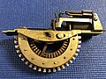
Two-axis stepping switch

[edit]

Slightly more complicated was the two axis stepping switch, (also called Strowger switch or two motion selector in Britain). Typically, a single compact group of wipers could connect to one of 100 (or 200) different fixed contacts, in ten levels. When the switch was idle, the wipers were disengaged from the fixed contacts. The wipers moved up and down on a vertical shaft, and rotated into the contact bank to make a connection. A spring, internal to the vertical shaft, returned the wipers to their home position at the bottom.

This type had two stepping coils with pawls and ratchets, one to raise the wipers to the desired banks of contacts, and one to rotate the wipers into the banks. These were commonly used in telephone switching with ten banks of ten contacts. The coils were typically driven by the electrical pulses derived from a rotary telephone dial. On a two-motion selector, as a digit was dialed, the wipers would step up the banks, then automatically rotate (self-step) into the selected bank until they found an "unused" outlet to the next switch stage. The last two digits dialed would operate the connector switch (final selector in Britain). The second to last digit would cause the wipers to move up and the last digit would cause them to rotate into the bank to the called customer's line outlet. If the line was idle then ringing voltage would be applied to the called line and ringing tone was sent to the calling line.

Another variant of the two-axis switch was the Stromberg-Carlson X-Y Switch which was quite common in telephone exchanges in the western USA. It was a flat mechanism, and the moving contacts moved both sidewise, as well as to and fro. It was quite reliable, and could be maintained by people with minimal training.

Applications

[edit]

Stepping switches are used in a variety of applications, other than telephone systems. By connecting several in series with the highest output of one going to the stepping contact of the next, a counter could be constructed. Or by feeding the stepping contact with an endless pulse train via a relay, and controlling the relay from the switch's own output, it can be made to automatically hunt for the first unpowered line (or powered, depending on whether the relay is normally open or normally closed). They could also be used as a demultiplexer, so that two input lines could control a number of output devices. One input line steps the switch until the correct device is selected, and the other then powers that device. Many other applications are possible.

Such switches were used in a series of Japanese cypher machines during World War 2: CORAL, JADE, PURPLE (the names were American). The British code-breaking machine called Colossus used rotary stepping switches, which was used to break the German Lorenz cipher.

References

[edit]
[edit]
Revisions and contributorsEdit on WikipediaRead on Wikipedia
from Grokipedia
A stepping switch, also known as a uniselector or rotary switch, is an electromechanical device that connects electrical lines by mechanically moving one or more wipers across banks of stationary contacts to route signals, most notably in early automatic exchanges. It operates on pulsed electrical inputs from a dial or similar mechanism, stepping the wiper in discrete increments—typically vertically to select a level and rotationally to select a contact—enabling the selection of one output from hundreds or thousands of possible connections without human intervention. This design revolutionized communication by automating call routing, replacing manual operators with a reliable, though maintenance-intensive, system sensitive to dust and wear. The stepping switch was invented in the late 19th century by Almon B. Strowger, an undertaker from , who sought to automate telephone switching after suspecting operator bias in call routing. Strowger filed his foundational patent (US 447,918) in 1889 (issued 1891), describing a two-motion selector with a central spindle driven by ratchet wheels and electromagnets to achieve precise vertical and rotary movement across up to 1,000 contacts arranged in 10 concentric rows of 100 each. The first commercial installation occurred in , in 1892, marking the debut of the Strowger Automatic Company, which evolved from Strowger's 1891 prototype. Refinements by engineers like Alexander Keith and the Erickson brothers in the 1890s improved reliability, introducing lighter designs and better release mechanisms, while companies such as Siemens-Halske licensed and adapted the technology internationally by 1907. In operation, a basic single-axis stepping switch rotates a wiper around a circular bank of contacts, while two-axis variants add vertical motion for multi-level selection, all controlled by intermittent pulses that energize solenoids to advance pawls against ratchets. Return to the home position is achieved via springs or a fusee mechanism, ensuring reset after each connection. These switches formed the core of step-by-step (Strowger) telephone systems, scaling to handle urban networks, but required periodic lubrication and cleaning due to mechanical friction. Post-World War II advancements integrated relays for hybrid systems, extending their lifespan until digital electronic switching largely supplanted them in the 1970s and 1980s. Beyond , stepping switches found diverse applications in the , including for signal distribution starting in 1928, totalizator machines for racetrack betting odds calculation, and cryptographic devices like Japan's machine (1937) and Britain's (1943–1945) for code-breaking. They also supported early computing efforts, such as Konrad Zuse's Z3 (1941) for relay sequencing and the University of Cambridge's (1949) for memory addressing. Though obsolete in modern , their legacy endures in influencing and automated control systems foundational to digital technology.

History

Invention and Early Development

The stepping switch, also known as the , was invented by , an undertaker from , in 1889 as a means to automate telephone connections and eliminate the perceived bias of human operators who could intercept or misdirect calls. Strowger's motivation stemmed from professional frustrations in his local telephone system, where manual operators allegedly favored competitors, prompting him to develop a mechanical device that allowed direct subscriber-to-subscriber switching without intervention. This innovation marked the birth of electromechanical automatic telephony, shifting from operator-controlled patch cords to pulse-driven selection mechanisms. Strowger's core design was detailed in U.S. Patent 447,918, granted on March 10, 1891, which described an automatic using switch-cylinders at the central office, each connected to a subscriber station via phonic wires. The system employed keys at the calling station to generate electrical pulses that activated magnets, levers, and pawls to rotate and longitudinally move a circuit-closing needle across perforated rows of contacts, enabling selection of up to 100 lines per switch without an operator. The first commercial implementation occurred on November 3, 1892, in , where the Strowger Automatic Telephone Exchange Company installed a system serving 75 subscribers, demonstrating the feasibility of automated switching on a small scale. This debut exchange used Strowger's original two-wire pulse configuration, relying on interruptions to step the switch mechanism. By the early , the design evolved from its initial crude form into a more reliable electromechanical system, incorporating dedicated electromagnets to control vertical and rotary stepping motions for precise wiper positioning on contact banks. Refinements by engineers like Alexander Keith and the Erickson brothers in the 1890s and early improved reliability, introducing lighter designs and better release mechanisms. These improvements addressed early limitations in signaling and mechanical actuation, allowing scalability to handle up to 10,000 lines through multi-level switching hierarchies. However, initial deployments faced mechanical reliability challenges, including wear on wipers and contact banks due to repeated stepping and friction, which could lead to intermittent connections and required frequent maintenance. Commercial production scaled through the Automatic Electric Company, established in 1901 to manufacture and market Strowger systems, achieving widespread installation in independent telephone networks by 1910 with facilities employing hundreds of workers. , the manufacturing arm of the , initially focused on alternative switching technologies but began adopting and producing Strowger-type step-by-step switches around 1919 to integrate automation into larger exchanges. This period solidified the stepping switch as a foundational technology in , paving the way for its dominance in automatic exchanges during the early .

Adoption in Telephony

The adoption of stepping switches in telephony gained momentum in the 1920s, as Strowger-type systems became integral to automatic exchanges in urban areas of the United States. These electromechanical devices enabled direct subscriber control via rotary dials, reducing reliance on manual operators and supporting the rapid expansion of telephone networks. By the mid-1920s, automatic installations based on stepping switch technology accounted for approximately 80% of new systems worldwide, with a significant majority in U.S. urban exchanges driving the shift to dial service. Internationally, the technology proliferated in during the same decade, facilitated by licensing and adaptation by major manufacturers. , a leading Swedish firm, incorporated Strowger-inspired principles into its automatic switching designs, culminating in the introduction of the 500-line switch in 1923, which marked a key step in continental deployment. This spread was supported by demonstrations at international exhibitions and collaborations, allowing stepping switches to underpin early automatic networks in countries like the and . Standardization advanced in the 1930s through innovations by the , which developed panel switching systems as an alternative to stepping switch technology, introducing common control for larger exchanges starting in the late 1910s and scaling up in the following decade. These panel designs influenced subsequent crossbar switches, first deployed in 1938, by retaining core electromechanical selection principles while improving efficiency and capacity for nationwide networks. Such developments ensured compatibility across Bell's infrastructure, paving the way for integrated electro-mechanical systems. The Rural Electrification Administration (REA), established in 1935, provided essential power infrastructure to remote areas, while its telephone loan program, starting in 1949, enabled the installation of compact automatic exchanges using stepping switch technology, such as Automatic Electric's Rural Automatic Exchange (RAX). This initiative dramatically expanded access, connecting previously isolated communities to national telephone grids. During , production of stepping switches surged to meet demands for , where they were ruggedized for field use in secure networks and integrated into devices for high-priority transmissions. By 1950, stepping switch systems had achieved vast scale, routing tens of millions of lines globally and forming the backbone of telephony. In the United States, the alone served approximately 30 million telephones by 1948, with step-by-step technology handling a substantial portion of urban and intercity traffic.

Principles of Operation

Basic Components and Mechanism

A stepping switch, also known as a uniselector in applications, consists of several core electromechanical components that enable selective circuit connections. The primary elements include a rotating wiper arm, which makes physical contact with fixed points to complete circuits; a of contacts arranged in an arc-shaped array, typically comprising 20 to 25 positions for sequential selection; a stepping () that drives motion; a release for resetting in certain designs; and a connected to the wiper assembly. The mechanism relies on electromagnetic actuation and mechanical linkage for positioning. When the stepping magnet's coil is energized, it attracts an armature attached to a pawl, which engages a ratchet wheel fixed to the , advancing the wiper arm incrementally. Spring tension on the armature and pawl ensures return to a rest position after each step, while a mechanism holds the ratchet in place to prevent backlash. The release magnet, in two-motion variants, similarly uses an to disengage the wiper from the and return it to a home position via spring action. In single-motion uniselectors, operation is rotary only, without vertical stepping, using similar pulsing but solely for angular selection. Electrically, these switches operate on direct current pulses, with typical voltages ranging from 24 to 48 V DC to energize the coils, derived from central battery supplies in telephone systems. Contact ratings are generally suited for low-power signaling, up to 1 A, to handle control signals without excessive wear. Design variations accommodate different applications, such as finger-style wipers using spring-loaded metal fingers for precise contact with button-like terminals, versus brush-style wipers for broader surface engagement. Multiple decks, or levels of banks vertically (up to 48 in complex assemblies), allow simultaneous handling of parallel circuits, with wiper sets aligned across decks for multi-line switching. Safety features include mechanical interlocking via pawls and detents to prevent overstepping or retrograde motion, ensuring the wiper stops accurately at designated positions. Some designs incorporate arc suppression elements, such as insulated barriers near contacts, to minimize sparking during make-and-break operations under load.

Stepping and Selection Process

In the stepping and selection process of a stepping switch, dial pulses generated by a rotary telephone interrupt the direct current loop, with each interruption energizing the stepping magnet to advance the wiper by one position per pulse. For instance, dialing the digit '0' produces 10 pulses, causing the wiper to step 10 times from its home position, while digits 1 through 9 produce correspondingly fewer pulses. This pulse-driven motion ensures precise positioning on the contact bank, where the wiper selects the appropriate termination for the next stage of the call. The selection logic operates in a cascaded manner across multiple switches to route calls from the originating subscriber to the destination. The first selector switch responds to the initial dialed digits to choose an exchange trunk by stepping to the corresponding level or position, after which subsequent switches, such as intermediate selectors and the final connector, handle the remaining digits to reach the subscriber line. Upon call completion or termination, a release pulse from the calling party's on-hook signal activates the release , homing the wipers back to the home position via spring action for rotary motion and gravity for vertical drop. Timing is critical to distinguish digits and prevent errors, with dial pulses typically occurring at a rate of 10 per second, consisting of a 40-millisecond make interval and a 60-millisecond break. An inter-digit pause of at least 200 milliseconds, often extending to 300-600 milliseconds in practice, allows the switch to settle and detect the end of one digit before processing the next via slow-release relays. Error handling integrates supervisory functions to manage call states, where contacts on the lead detect line conditions: a grounded sleeve indicates a busy line, triggering a busy tone via the switch's tone connections, while an idle line (battery potential) proceeds to ringing. In basic systems, the connection persists until the caller hangs up; later variants may include timeout circuits for unanswered calls. If no idle path is found during selection, such as at an overflow position, a fast busy tone (two beeps per second) alerts the caller. The positioning follows a straightforward calculation, where the number of steps equals the dialed digit value, adjusted modulo the bank size to prevent overrun: n=dmodbn = d \mod b, with dd as the digit (1-9, or 10 for 0) and bb the number of positions in the bank. For a 23-position bank, dialing 5 advances the wiper exactly 5 positions from home.

Types

Single-Motion Stepping Switches

Single-motion stepping switches, also known as uniselectors, feature a centered on a single rotary motion, where a wiper assembly rotates around a circular bank of contacts spanning an arc of approximately 173 degrees. The wiper, often comprising multiple levels (commonly 3 to 8), moves across 20 to 30 contacts per level, enabling selection across the contact arc while supporting simultaneous operation of several contact sets for efficient circuit handling. This rotary mechanism relies on electromagnetic pulsing to advance the wiper step-by-step, making it suitable for 2-wire circuits in basic routing tasks. The primary advantages of single-motion stepping switches lie in their simplicity and low cost, stemming from a standardized that eliminates complex multi-axis components and, in some variants, a dedicated release . They offer fast selection speeds for small contact groups, typically achieving 50-68 steps per second under self-interruption drive, which supports rapid hunting and connection in low-complexity systems. During operation, power consumption is low, contributing to their economic viability in early electromechanical networks. Despite these benefits, single-motion switches are limited to one-dimensional selection, necessitating multiple units in series to achieve full routing in larger systems, which increases overall complexity and space requirements. The concentration of motion on a single axis also leads to higher wear on the wiper and bank contacts over time, potentially reducing compared to multi-motion designs. Historically, uniselectors were prominently adopted in by the British for automatic telephone exchanges, with trials at sites like Regent Exchange in demonstrating their role in scaling early dial systems to handle up to 200 lines.

Two-Motion Stepping Switches

Two-motion stepping switches employ a dual-axis mechanism in which a carriage, carrying the wiper assembly, first moves vertically along a central shaft to select one of typically 10 levels (with variants up to 20 levels, as in line finders) before rotating horizontally to one of typically 10 positions on the selected level. This hierarchical design, driven by electromagnets for vertical stepping, rotary motion, and release, enables precise selection across stacked banks of contacts, with the wiper connected via flexible leads to maintain circuit integrity during movement. The advantages of this configuration lie in its efficiency for scaling telephone exchanges, as it consolidates multiple single-motion selectors into one unit, thereby reducing the overall number of switches required and supporting capacities exceeding 500 lines per unit through arrangements. In practice, a standard 10-level by 10-position variant handles 100 terminals directly, but multilevel cascading extends this to larger networks. Historically, Almon Strowger's original 1891 design incorporated this two-motion principle, patented as an electromechanical selector for automatic telephony. By the , systems widely adopted rotary line finders based on this mechanism to connect subscriber lines to the switching hierarchy, accessing up to 200 lines via dual banks per finder. Despite these benefits, the dual-motion setup introduces greater mechanical complexity than single-motion alternatives, leading to higher failure rates from on moving parts and necessitating regular maintenance such as and alignment. Operation is inherently slower, with vertical preceding , which delays connection times in multi-stage exchanges.

Applications

Telephone Exchange Systems

Stepping switches served as the core components of early automatic telephone exchanges, enabling subscriber-initiated call routing without operator intervention. Line finders, a type of uniselector stepping switch, continuously scanned for off-hook conditions on subscriber lines and seized an idle path to connect the calling party to the first selector upon detecting a request. Selectors, operating in a step-by-step manner, advanced their wipers in response to dial pulses to route calls through successive stages toward the destination. Tandem switches, often configured as multi-stage selectors, handled inter-exchange traffic by interconnecting local offices for toll or long-distance calls, optimizing network efficiency. The routing hierarchy in stepping switch-based exchanges varied by system scale and call type. For small local networks with 2-digit numbering, a line finder directly fed into a final selector (also called a connector), which completed intra-exchange connections using the two dialed digits to select the level and bank. In larger or toll-capable setups employing 3-digit plans, an additional group selector stage was inserted after the first selector, allowing the first digit to choose a group of hundreds while subsequent digits refined the path, thus supporting up to 1,000 lines per exchange. This modular hierarchy minimized equipment per subscriber and facilitated expansion. By the 1940s, stepping switch systems evolved to incorporate registers for temporary storage and number translation, particularly in director-equipped designs that enabled two-stage dialing for urban areas and improved call handling in . These registers, often relay-based, captured dialed from the calling line before forwarding it to selectors, reducing timing sensitivities and supporting features like abbreviated dialing. Hybrid integrations paired stepping selectors with crossbar switches for incoming trunks or roles, leveraging the former's simplicity for local routing and the latter's speed for high-traffic links, thereby enhancing overall system reliability and capacity. Performance in these exchanges prioritized reliability over speed, with typical call setup times ranging from 5 to 10 seconds to accommodate mechanical stepping delays and manual dialing pauses. Blocking probabilities were kept under 2% in engineered configurations through sufficient switch multiples and grading, ensuring most calls connected without retry. As an illustrative case, the inaugural full stepping switch exchange in , opened on November 3, 1892, by the Strowger Automatic Telephone Exchange Company, initially serving about 75 lines and demonstrating practical automation for a small community.

Non-Telephony Uses

Stepping switches found significant applications in early electronic computing for program control and sequencing. In the , the first general-purpose electronic computer completed in 1945, electronic stepper units (ring counters) were integral to the master programmer, enabling branching and looping operations by dynamically altering program information through counters. Similarly, uniselectors—a type of stepping switch—were employed in the Colossus code-breaking machines developed during at , where they facilitated pulse-controlled switching for cryptographic processing and output selection. In military systems, particularly during , stepping switches supported control mechanisms in naval and applications. Manufacturers like American Totalisator produced rotary stepping switches for integration into shipboard control systems, enhancing automated signal routing in combat environments. These devices contributed to reliable electromechanical operations in harsh conditions, such as aboard submarines, where they handled sequential activations for targeting and scanning functions. Industrial control systems in the mid-20th century leveraged stepping switches for in and sequencing tasks. By the , they served as sequence controllers in assembly lines, selecting tools and routing power to machinery through pulse-driven rotations, reducing reliance on multiple relays for complex operations. Their durability and precision made them suitable for environments requiring repetitive, reliable switching, such as dispensers that used stepped relays to select and release items based on coin inputs. Beyond these, stepping switches appeared in broadcasting equipment for non-telephonic signal management. In 1928, the implemented them to automate connections between radio studios and transmitters, routing audio programs over lines via electromechanical stepping for efficient program distribution. Adaptations like DC-powered variants emerged in the for remote applications, including in oil fields, where they enabled sequential data selection and control over long distances without AC infrastructure. These uses highlighted the device's versatility in electromechanical sequencing outside communication networks.

Decline and Modern Relevance

Transition to Electronic Switching

The transition from stepping switches to electronic switching systems in telephony was driven primarily by the inherent limitations of electromechanical technology, including mechanical wear from repeated stepping motions and contact degradation, which necessitated frequent maintenance and adjustments. Space inefficiency was another critical factor, as stepping switches required dedicated hardware for each subscriber line, leading to bulky installations that consumed significant floor space in exchange buildings compared to the compact design of electronic systems. Additionally, the slow mechanical setup times for call connections—often involving multiple relay operations—could not compete with the near-instantaneous electronic processing speeds, limiting scalability as telephone traffic volumes grew exponentially post-World War II. Technical shortcomings further accelerated the shift, with stepping switches proving highly susceptible to environmental factors such as accumulation on wipers and contacts, as well as that caused misalignment and unreliable operation. The introduction of touch-tone dialing in 1963 by the marked a pivotal obsolescence for pulse-based systems reliant on stepping mechanisms, as dual-tone multi-frequency signaling enabled faster, more reliable digit transmission incompatible with traditional electromechanical designs without costly retrofits. A major milestone in this transition was the deployment of Bell Laboratories' No. 1 Electronic Switching System (No. 1 ESS) in Succasunna, , on May 30, 1965, representing the first large-scale stored-program control electronic exchange capable of handling both residential and traffic with improved reliability through duplicated processors and software-based control. This system marked the beginning of widespread adoption, with full replacement of electromechanical switches in the United States largely completed by the , as evidenced by large-scale retirements starting in 1977. In , the transition extended into the 1990s, with digital systems like the UK's becoming standard from the early onward, though some electromechanical installations persisted longer in rural areas. Economically, electronic systems offered substantial cost savings per line through reduced maintenance, lower power consumption, and minimized space requirements, enabling operators to serve more subscribers without proportional infrastructure expansion. The phase-out also led to the salvage and of millions of stepping switches, with materials like metals and relays repurposed, contributing to in the sector during the 1970s and 1980s. The adoption of electronic switching technology saw rapid uptake in developed markets starting in the late , driven by efficiency gains. The last major installations of stepping switches occurred in developing regions during the , where cost constraints delayed full adoption until digital alternatives became more affordable.

Contemporary Applications and Legacy

In the , stepping switches persist primarily through restorations and niche hobbyist projects that maintain operational examples for demonstration and educational purposes. Enthusiasts and museums have restored vintage Strowger-type stepping switches, originally from early 20th-century telephone exchanges, to showcase their electromechanical functionality. For instance, the Telephone Museum of features a custom-built Strowger switching demonstration unit capable of connecting up to 12 s with three simultaneous paths, allowing visitors to experience dial-pulse routing and the characteristic clicking sounds of the mechanism. Similarly, hobbyists document restoration efforts, such as salvaging and refurbishing 1960s-era mechanical switches to restore full operability, often sharing step-by-step processes for cleaning contacts and repairing pawl mechanisms. These projects highlight the durability of the switches' simple electromagnet-and-ratchet , which requires minimal electronic components. The legacy of stepping switches endures in telecommunications museums, where operational demonstrations preserve their role in the history of automated switching and serve as interactive exhibits. The in displays a fully assembled Community Dial Office using Strowger-type rotary stepping switches, enabling visitors to observe step-by-step pulse-based selection in a recreated rural exchange environment. Likewise, the Maitland Historical & in maintains a working switchroom with energized Strowger Step-by-Step and XY stepping switches, offering free public access to see the devices in action. These installations not only honor the technology's influence on global but also educate on principles, such as actuation and mechanical latching, through hands-on dialing simulations. Revivals of stepping switch technology appear in custom hobbyist builds that emulate historical telephone exchanges for retro telephony enthusiasts. Projects like the Strowger Switching Demo Unit at the Telephone Museum of Prince Edward Island, constructed from 1950s surplus parts, revive the step-by-step logic for small-scale networks supporting up to 40 lines with party ringing. Online communities document similar restorations, including the integration of vintage rotary dials with preserved switches to create functional intercoms or demonstration circuits. This resurgence underscores the switches' conceptual impact on modern switching theory, as their pulse-driven selection principles parallel routing algorithms in voice-over-IP systems, though fully electronic implementations have replaced them. Looking ahead, stepping switches hold conceptual potential in hybrid electro-mechanical systems for harsh environments due to their inherent resilience against electromagnetic pulses (EMP) compared to semiconductor-based alternatives. Older electromechanical relays, including stepping variants, demonstrate superior EMP tolerance by avoiding vulnerable microelectronics, as evidenced in tests where such devices continued functioning post-exposure while digital systems failed. Research into electro-mechanical actuators for space applications further explores their reliability in extreme conditions like radiation and vacuum, where minimal reliance on solid-state components reduces failure risks. Although not in widespread production, these attributes position revived or hybrid stepping switch designs as candidates for EMP-hardened infrastructure, such as backup communication relays in critical facilities.

References

Add your contribution
Related Hubs
User Avatar
No comments yet.