
Community hub
Recent from talks
Contribute something to knowledge base
Content stats: 0 posts, 0 articles, 1 media, 0 notes
Members stats: 0 subscribers, 0 contributors, 0 moderators, 0 supporters
Subscribers
Supporters
Contributors
Moderators
Hub AI
Railroad switch AI simulator
(@Railroad switch_simulator)
Hub AI
Railroad switch AI simulator
(@Railroad switch_simulator)
Railroad switch
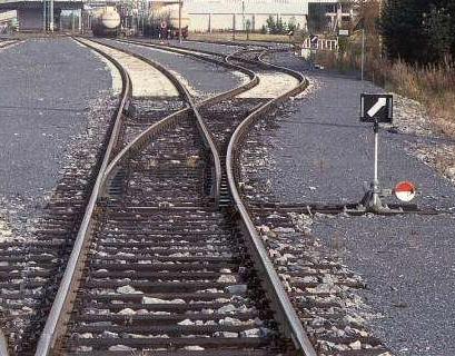
A railroad switch (AE), turnout, or (set of) points (CE) is a mechanical installation enabling railway trains to be guided from one track to another, such as at a railway junction or where a spur or siding branches off.
The parts of a turnout are known by different names in different jurisdictions. The main terms in US and UK usage are shown in the selectable diagrams. In this article, the US term is listed first and UK second, in parentheses.
The most common type of switch consists of a pair of linked tapering rails, known as points (switch rails or point blades), lying between the diverging outer rails (the stock rails). These points can be moved laterally into one of two positions to direct a train coming from the point blades toward the straight path or the diverging path. A train moving from the narrow end toward the point blades (i.e. it will be directed to one of the two paths, depending on the position of the points) is said to be executing a facing-point movement.
For many types of switch, a train coming from either of the converging directions will pass through the switch regardless of the position of the points, as the vehicle's wheels will force the points to move. Passage through a switch in this direction is known as a trailing-point movement and switches that allow this type of movement without damage to the mechanism are called trailable switches.[page needed] In turn, these can either be non-resettable or resettable, meaning they either require on-site intervention to return the switch to operation after a trailing point movement or can continue operating with no in-person actions.
A switch generally has a straight "through" track, such as the mainline, and a diverging route – respectively termed "normal" and "reverse" routes. The handedness of the installation is described by the side that the diverging track leaves. Right-hand switches have a diverging path to the right of the straight track, when coming from the point blades (switch blades), and a left-handed switch has the diverging track leaving to the opposite side. In many cases, such as rail yards, many switches can be found in a short section of track, sometimes with switches going both to the right and left (although it is better to keep these separated as much as feasible). Sometimes a switch merely divides one track into two; at others, it serves as a connection between two or more parallel tracks, allowing a train to switch between them. In many cases, where a switch is supplied to leave a track, a second is supplied to allow the train to reenter the track some distance down the line; this allows the track to serve as a siding, allowing a train to get off the track to allow traffic to pass (this siding can either be a dedicated short length of track, or formed from a section of a second, continuous, parallel line), and also allows trains coming from either direction to switch between lines; otherwise, the only way for a train coming from the opposite direction to use a switch would be to stop, and reverse through the switch onto the other line, and then continue forwards (or stop, if it is being used as a siding).
A straight track is not always present; for example, both tracks may curve, one to the left and one to the right (such as for a wye switch), or both tracks may curve, with differing radii, while still in the same direction. Switches consume a relatively high proportion of a railway maintenance budget.
Simple single-bladed switches were used on early wooden railways to move wagons between tracks. As iron-railed plateways became more common in the eighteenth century, cast iron components were made to build switches with check rails.[page needed] In 1797, John Curr described the system that he developed which used a single iron blade, hinged on a vertical pin that was tapered to lie against the plateway.[page needed] By 1808, Curr's basic design was in common use.[page needed]
The use of a sprung rail, giving a smooth transition, was patented by Charles Fox in 1838.
Railroad switch
A railroad switch (AE), turnout, or (set of) points (CE) is a mechanical installation enabling railway trains to be guided from one track to another, such as at a railway junction or where a spur or siding branches off.
The parts of a turnout are known by different names in different jurisdictions. The main terms in US and UK usage are shown in the selectable diagrams. In this article, the US term is listed first and UK second, in parentheses.
The most common type of switch consists of a pair of linked tapering rails, known as points (switch rails or point blades), lying between the diverging outer rails (the stock rails). These points can be moved laterally into one of two positions to direct a train coming from the point blades toward the straight path or the diverging path. A train moving from the narrow end toward the point blades (i.e. it will be directed to one of the two paths, depending on the position of the points) is said to be executing a facing-point movement.
For many types of switch, a train coming from either of the converging directions will pass through the switch regardless of the position of the points, as the vehicle's wheels will force the points to move. Passage through a switch in this direction is known as a trailing-point movement and switches that allow this type of movement without damage to the mechanism are called trailable switches.[page needed] In turn, these can either be non-resettable or resettable, meaning they either require on-site intervention to return the switch to operation after a trailing point movement or can continue operating with no in-person actions.
A switch generally has a straight "through" track, such as the mainline, and a diverging route – respectively termed "normal" and "reverse" routes. The handedness of the installation is described by the side that the diverging track leaves. Right-hand switches have a diverging path to the right of the straight track, when coming from the point blades (switch blades), and a left-handed switch has the diverging track leaving to the opposite side. In many cases, such as rail yards, many switches can be found in a short section of track, sometimes with switches going both to the right and left (although it is better to keep these separated as much as feasible). Sometimes a switch merely divides one track into two; at others, it serves as a connection between two or more parallel tracks, allowing a train to switch between them. In many cases, where a switch is supplied to leave a track, a second is supplied to allow the train to reenter the track some distance down the line; this allows the track to serve as a siding, allowing a train to get off the track to allow traffic to pass (this siding can either be a dedicated short length of track, or formed from a section of a second, continuous, parallel line), and also allows trains coming from either direction to switch between lines; otherwise, the only way for a train coming from the opposite direction to use a switch would be to stop, and reverse through the switch onto the other line, and then continue forwards (or stop, if it is being used as a siding).
A straight track is not always present; for example, both tracks may curve, one to the left and one to the right (such as for a wye switch), or both tracks may curve, with differing radii, while still in the same direction. Switches consume a relatively high proportion of a railway maintenance budget.
Simple single-bladed switches were used on early wooden railways to move wagons between tracks. As iron-railed plateways became more common in the eighteenth century, cast iron components were made to build switches with check rails.[page needed] In 1797, John Curr described the system that he developed which used a single iron blade, hinged on a vertical pin that was tapered to lie against the plateway.[page needed] By 1808, Curr's basic design was in common use.[page needed]
The use of a sprung rail, giving a smooth transition, was patented by Charles Fox in 1838.
Recent media
Recent media