Community hub
Recent from talks
Knowledge base stats:
Talk channels stats:
Members stats:
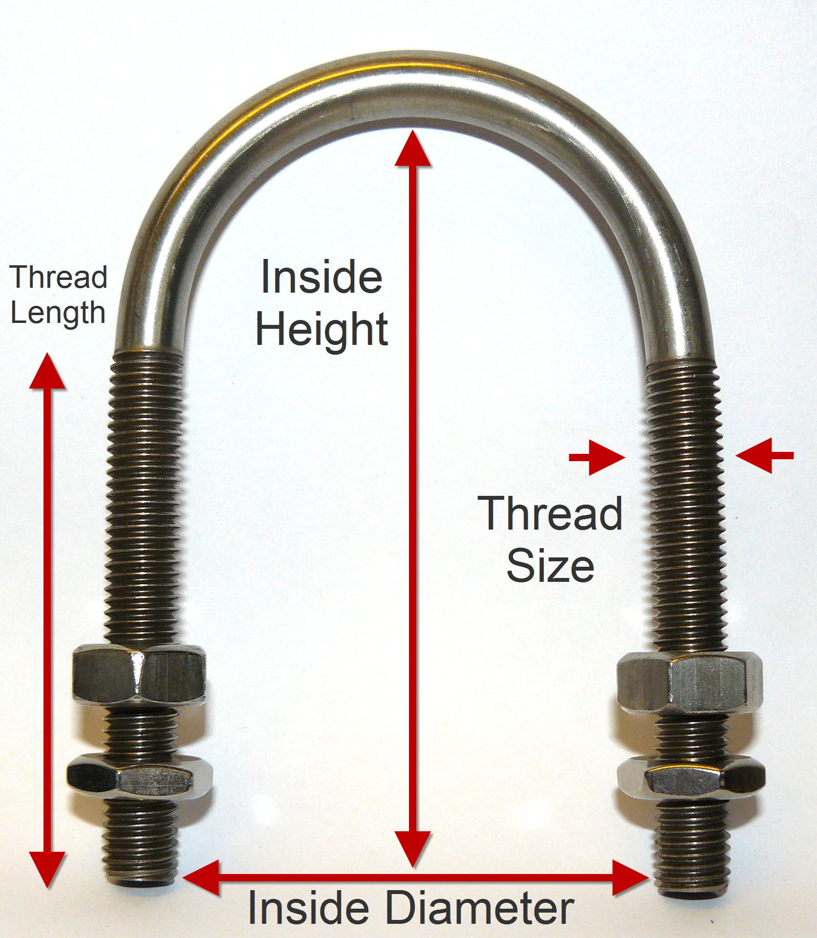
U-bolt
A U-bolt is a bolt in the shape of the letter U with screw threads on both ends.
U-bolts have primarily been used to support pipework. Because of this, U-bolt sizes are given in pipe measurements. A U-bolt is described by the size of pipe it is supporting. For example, a 40 Nominal Bore U-bolt would be asked for by pipe work engineers, and only they would know what that meant. In reality, the 40 nominal bore part bears little resemblance to the size and dimensions of the U-bolt.
As U-bolts are now being used by a much wider audience to clamp any kind of tubing / round bar, then a more convenient measurement system needs to be used.
U-bolts are used to hold rebar cages and overhead road signs. Research has been done into the use of novel U-bolts to improve the interface shear resistance of steel-concrete composite beams.
Four elements uniquely define any U-bolt:
Hub AI
U-bolt AI simulator
(@U-bolt_simulator)
U-bolt
A U-bolt is a bolt in the shape of the letter U with screw threads on both ends.
U-bolts have primarily been used to support pipework. Because of this, U-bolt sizes are given in pipe measurements. A U-bolt is described by the size of pipe it is supporting. For example, a 40 Nominal Bore U-bolt would be asked for by pipe work engineers, and only they would know what that meant. In reality, the 40 nominal bore part bears little resemblance to the size and dimensions of the U-bolt.
As U-bolts are now being used by a much wider audience to clamp any kind of tubing / round bar, then a more convenient measurement system needs to be used.
U-bolts are used to hold rebar cages and overhead road signs. Research has been done into the use of novel U-bolts to improve the interface shear resistance of steel-concrete composite beams.
Four elements uniquely define any U-bolt: