Community hub
Bent (structural)
View on WikipediaA bent in American English is a transverse rigid frame (or similar structures such as three-hinged arches). Historically, bents were a common way of making a timber frame; they are still often used for such, and are also seen in small steel-frame buildings, where the term portal frame is more commonly used.
The word "bent" is also used for the horizontal element of a two-pier bridge support, which is a support consisting of two vertical piers, each approximately at the outer edge of the bridge deck, and a single horizontal element connecting the tops of the two piers. In British English this assembly is called a "cross frame". An "outrigger bent" is one where the vertical piers are located outside the bridge's deck, hence the horizontal bent is wider than the bridge deck.
The term bent is probably an archaic past tense of the verb to bind, referring to the way the timbers of a bent are joined together. The Dutch word is bint (past participle gebint),[1] the West Frisian is bynt, and the German is bind. Compare this with the term bend for a class of knots.
Bents are the building blocks that define the overall shape and character of a structure. They do not have any sort of pre-defined configuration in the way that a Pratt truss does. Rather, bents are simply cross-sectional templates of structural members, i.e., rafters, joists, posts, pilings, etc., that repeat on parallel planes along the length of the structure. The term bent is not restricted to any particular material. Bents may be formed of wooden piles, timber framing,[2] steel framing, or even concrete.[3]
Construction
[edit]Traditional timber frame bents were one component of a braced frame in timber framing. Historically, mortise and tenon joints were used to joint bents to posts and beams due to the unavailability of nails.[4]
Bents are generally pre-assembled, either at the timber framing company's shop or at the construction site. After the basic post and beam structure of the frame has been set in place, the bents are then lifted and simply lowered into place one by one by the crane. Next, the workers bring in additional members, purlins, which tie them together and give the frame a more rigid structure. This process is very safe and efficient, as it allows a crew to assemble a large portion of the frame without ever stepping off the ground. This, in turn, minimizes the amount of time that the crew must spend several stories in the air clambering along beams not much wider than their own feet.[citation needed]
Gallery
[edit]-
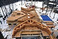 A stack of bents ready to be "flown" into place by a crane
 -
![A worker directs the crane operator with hand signals as a bent is flown into place [photo reversed]](//upload.wikimedia.org/wikipedia/commons/thumb/3/36/Large_Flying_Bent.jpg/120px-Large_Flying_Bent.jpg) A worker directs the crane operator with hand signals as a bent is flown into place [photo reversed]
A worker directs the crane operator with hand signals as a bent is flown into place [photo reversed] -
 A mixed type of bent framing in the Netherlands. The left side is in Dutch is framed as a dekbalkgebint (roof beam bent) and the right side is an ankerbalkgebint (anchor beam bent). Image: Cultural Heritage Agency of the Netherlands.
 -
 An anchor beam bent in the Netherlands. Image: Cultural Heritage Agency of the Netherlands.
 -
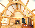 A bent in a finished timber frame home in the form of a hammerbeam truss.

![A worker directs the crane operator with hand signals as a bent is flown into place [photo reversed]](https://en.wikipedia.org/wiki/File:Large_Flying_Bent.jpg)


See also
[edit]- Barn raising
- Pike pole
- Gin pole
- Timber roof truss
- Tau Beta Pi — engineering society whose seal incorporates a bent
Notes
[edit]- ^ Woordenboek van de Limburgse dialecten II-9, Volume 2; Volume 9 By Antonius A Weijnen Joep Kruijse
- ^ Charles Lee Crandall and Fred Asa Barnes, Railroad Construction, McGraw Hill, New York, 1913; Section 97, Principles of Construction, pages 213-215.
- ^ W. S. Lacher, The Track Elevation Subways in Chicago, Railway Age Gazette, Vol 56, No, 10 (March 6, 1914); page 461.
- ^ Walsh, Harold Vandervoort (1923). The Construction of the Small House. New York: C. Schribner's sons. pp. 38–40.
References
[edit]- Benson, Ted (1981). Building the Timber Frame House: The Revival of a Forgotten Art. Simon and Schuster. ISBN 978-1-4391-0707-2.
External links
[edit]- Glossary Useful terms in the timber framing trade.
- Blog Entry Some good pictures and a short narrative about raising bents.