

Community hub
Recent from talks
Contribute something
Nothing was collected or created yet.
Purlin
View on Wikipedia
A purlin (or historically purline, purloyne, purling, perling) is a longitudinal, horizontal, structural member in a roof. In traditional timber framing there are three basic types of purlin: purlin plate, principal purlin, and common purlin.
Purlins also appear in steel frame construction. Steel purlins may be painted or greased for protection from the environment.
Etymology
[edit]Information on the origin of the term "purlin" is scant. The Oxford Dictionary suggests a French origin, with the earliest quote using a variation of purlin in 1447, though the accuracy of this claim has been disputed.
In wood construction
[edit]Purlin plate
[edit]A purlin plate in wood construction is also called an "arcade plate" in European English,[1] "under purlin", and "principal purlin". The term plate means a major, horizontal, supporting timber. Purlin plates are beams which support the mid-span of rafters and are supported by posts. By supporting the rafters they allow longer spans than the rafters alone could span, thus allowing a wider building. Purlin plates are very commonly found in large old barns in North America. A crown plate has similarities to a purlin plate but supports collar beams in the middle of a timber-framed building.
Principal purlin
[edit]Principal purlins in wood construction, also called "major purlins" and "side purlins," are supported by principal rafters and support common rafters in what is known as a "double roof" (a roof framed with a layer of principal rafters and a layer of common rafters). Principal purlins are further classified by how they connect to the principal rafters: "through purlins" pass over the top; "butt purlins" tenon into the sides of the principal rafters; and "clasped purlins," of which only one historic U.S. example is known,[citation needed]) are captured by a collar beam. Through purlins are further categorized as "trenched," "back," or "clasped;" butt purlins are classified as "threaded," "tenoned," and/or[clarification needed] "staggered."[2]
Common purlin
[edit]Common purlins in wood construction, also called a "major-rafter minor-purlin system".[3] Common purlins are typically "trenched through" the top sides (backs) of principal rafters and carry vertical roof sheathing (the key to identifying this type of roof system). Common purlin roofs in North America are found in areas settled by the English and may have been a new invention in the Massachusetts Bay Colony. No examples of framed buildings with common purlin roofs have been reported in England, however some stone barns in England have vertically boarded, common purlin roofs. Historically, these roofs are found in New England, the highest concentration in Maine, and isolated parts of New York and along the St. Lawrence River in Canada. One of the oldest surviving examples is in the Coffin House in Newbury, Massachusetts, from 1678. The purpose of a common purlin roof may be they allow a board roof, that is a roof of nothing but vertically laid boards with seams covered with battens or another layer of boards.[4]
In steel construction
[edit]In steel construction, the term purlin typically refers to roof framing members that span parallel to the building eave,[5] and support the roof decking or sheeting. The purlins are in turn supported by rafters or walls. Purlins are most commonly used in Steel Framed Building Systems, where Z-shapes are utilized in a manner that allows flexural continuity between spans.
Steel industry practice assigns structural shapes representative designations for convenient shorthand description on drawings and documentation: Channel sections, with or without flange stiffeners, are usually referenced as C shapes; Channel sections without flange stiffeners are also referenced as U shapes; Point symmetric sections that are shaped similar to the letter Z are referenced as Z shapes. Section designations can be regional and even specific to a manufacturer. In steel building construction, secondary members such as purlins (roof) and girts (wall) are frequently cold-formed steel C, Z or U sections, (or mill rolled) C sections.
Cold formed members can be efficient on a weight basis relative to mill rolled sections for secondary member applications. Additionally, Z sections can be nested for transportation bundling and, on the building, lapped at the supports to develop a structurally efficient continuous beam across multiple supports.
Gallery
[edit]Note: The sketches in this section reference terminology commonly used in the UK and Australia.[6]
-
 A section through lightweight timber-frame construction showing the position of under purlins
 -
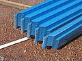 Roll-formed metal roof purlins, also called roof battens. They are cropped to the angle of the purlin top cuts and can be lapped for joining.
 -
 Metal purlins or roof battens screwed to roof gang-nail-type trusses
 -
 Hardwood purlins fixed to steel supports on a skillion roof and main roof. House under construction, tropical North Australia.
 -
 C and Z purlins in all-steel construction
 -
 The ability of Z purlins to rotate 180 degrees and fit together
 -
 Portal rafters made from C section material supporting Z roof purlins
 -
 A traditionally framed timber queen post roof showing the placement of principal purlins or purlin plates supporting common rafters
 -
 Timber roof truss with purlins


See also
[edit]References
[edit]- ^ Harris, Richard. "Bays, frames and boxes." Discovering timber-framed buildings. 3rd revised ed. Aylesbury: Shire Publications, 1979. 10
- ^ Alcock, N. W. "Purlins." Recording timber-framed buildings: an illustrated glossary. York, England: Council for British Archaeology, 1996. G14, F12.
- ^ Hubka, Thomas C. "The Buildings". Big house, little house, back house, barn: the connected farm buildings of New England. Hanover [N.H.]: University Press of New England, 1984. p. 41.
- ^ The origin of the common purlin roof is my studied opinion. These roofs were historically common in northern Europe and may have been brought to the New World by the Pilgrims after their two decades of living in the Netherlands.
- ^ "What are Purlins - Metsec". voestalpine Metsec. voelstapine Metsec. Retrieved 3 April 2024.
- ^ Glossary of Australian Building Terms - Third Edition.(NCRB)
External links
[edit]This article incorporates text from a publication now in the public domain: Chisholm, Hugh, ed. (1911). "Purlin". Encyclopædia Britannica. Vol. 22 (11th ed.). Cambridge University Press. p. 665.

Purlin
View on GrokipediaOverview
Definition and Terminology
A purlin is a longitudinal, horizontal structural member in a roof framework that provides secondary support to the roof deck, sheathing, or cladding while transferring loads to primary elements such as rafters, trusses, or walls.[1][4] In structural engineering, purlins are essential for distributing dead loads (from roofing materials), live loads (such as snow or wind), and ensuring overall roof stability, typically spanning between principal rafters or building frames.[5] They are commonly fabricated from timber in traditional construction or cold-formed steel in modern applications, with steel purlins offering high strength-to-weight ratios and corrosion resistance through galvanization.[2][6] Terminology surrounding purlins varies by material and construction type. In timber framing, a principal purlin (also known as a purlin plate or arcade plate) is a major horizontal beam that runs parallel to the ridge, spanning from gable to gable and supporting multiple common rafters.[7][8] In contrast, a common purlin is a smaller, regularly spaced horizontal member that connects to principal rafters and directly carries the roof sheathing or battens.[7] Additional variants in timber include through purlins (passing through the principal rafter), clasped purlins (housed within rafter joints), and back purlins (positioned behind the rafter).[9] In steel construction, purlins are classified by cross-sectional profile, with C-section purlins featuring a C-shaped form suitable for wall cladding (as side rails) or smaller spans, and Z-section purlins providing enhanced overlap and load distribution for longer spans in roofs.[1][2] The term side rail specifically denotes a purlin-like member used horizontally for wall support, distinguishing it from roof applications.[1] These terms are standardized in engineering specifications, such as those from the American Iron and Steel Institute (AISI), which define purlins as horizontal members supporting roof covering in cold-formed steel systems.[6]Functions in Roof Systems
Purlins serve as essential secondary structural members in roof systems, positioned horizontally to support the roof covering, such as sheathing or decking materials, and to transfer various loads from the roof surface to the primary framing elements like rafters, trusses, or beams. By spanning between these primary members, purlins reduce the effective span of the roof covering, thereby enhancing overall stability and preventing excessive deflection under load. This load distribution function is critical in both timber and steel constructions, where purlins bear vertical gravity loads—including dead loads from the roofing materials and live loads such as snow or maintenance personnel—as well as uplift forces from wind.[10][11] In addition to load transfer, purlins contribute to the lateral and torsional stability of the roof framework by bracing the primary members against buckling and providing continuity across spans, often through lapping or direct connections. For instance, in timber roof systems, purlins typically span between trusses spaced 1.2 to 3.7 meters (4 to 12 feet) apart, with purlins installed at spacings of 0.6 to 1.2 meters (2 to 4 feet) along the trusses, 0.6 meters (2 feet) being common in post-frame buildings, allowing them to efficiently distribute loads while minimizing material use. In steel roof systems, particularly those using cold-formed C- or Z-sections, purlins resist bending moments, shear forces, and web crippling, with sheathing providing restraint against lateral-torsional buckling—full restraint from through-fastened panels or partial (R-factor of 0.70 to 0.95) from standing seam roofs. This bracing effect ties the roof components together, improving the system's resistance to horizontal forces like wind or seismic activity.[10][11] The design of purlins also accounts for anchorage and connection mechanisms to prevent uplift and rotation, such as anti-roll clips that limit lateral displacement to one-twentieth of the purlin depth. Overall, these functions ensure the roof system's integrity, enabling efficient construction with spans up to several meters while maintaining structural performance under combined loading conditions as specified in standards like the AISI for steel and NDS for wood.[11]Etymology and Historical Development
Etymology
The term "purlin" first appears in Middle English, with the earliest recorded use dating to 1439.[12] Its origin is uncertain, but it is possibly borrowed from an unrecorded French noun purloigne, potentially in the sense of "extension," akin to Old French purloignier meaning "to extend" or "prolong."[12] Early variants include "purlyn" and "purloyne," reflecting late Middle English forms from around 1400–1450, which may also relate to Anglo-Latin perliō.[13] This etymology aligns with the structural role of a purlin as a horizontal beam that "extends" support across a roof framework, though direct linguistic evidence remains scant.[12]Evolution from Timber to Modern Materials
The use of purlins as horizontal structural members in roof systems originated in ancient and medieval timber construction, where they provided intermediate support for rafters and roof coverings. In early medieval England, "sans-purlin" roofs dominated, consisting of simple rafter couples without intermediate purlins, suitable for thatched or tiled coverings in halls and vernacular buildings. By the mid-14th century, central purlins braced to crown posts on tie beams became widespread in southeast England, spanning up to 200 years in use and allowing for larger roof spans with oak timbers.[14] During the late 15th century, side purlins—either butt-purlins tenoned into principal rafters or clasped purlins housed into rafters and principals—emerged as common alternatives, particularly in regions like the Midlands and Wales, enhancing load distribution and enabling steeper pitches for better weatherproofing. These timber purlins, typically hewn from local hardwoods like oak or elm, were integral to cruck-framed and box-framed roofs from the 12th to 15th centuries, with ridge purlins and wall plates adding stability. In post-medieval periods (17th-18th centuries), king-post and queen-post trusses incorporated purlins with iron straps and bolts for reinforcement, shifting to imported softwoods like pine due to deforestation, as seen in designs by engineers like the Tredgold brothers around 1820.[14][15] The transition to modern materials accelerated during the Industrial Revolution in the mid-19th century, as wrought iron and early steel production enabled hybrid systems combining timber purlins with iron ties and brackets, exemplified by the Crystal Palace in London (1851), which featured prefabricated timber purlins supported by cast-iron columns and wrought-iron girders for its vast glass roof. The Bessemer process (1856) revolutionized steel manufacturing, making mild steel more affordable and reliable than wrought iron by the early 1900s, leading to its adoption in roof framing; the London County Council Act (1909) standardized stresses for steel beams in roofs, facilitating their use as purlins with section moduli suited for spans up to 20 feet.[16][15] By the early 20th century, fully steel purlins supplanted timber in industrial and commercial construction due to steel's superior tensile strength, fire resistance, and resistance to rot, with C-shaped and Z-shaped cold-formed steel purlins invented around this period to provide lightweight, roll-formed sections for efficient spanning parallel to eaves. The British Standard Beams (1903) and later BS449 (1932) codified steel purlin properties, such as channels with masses from 4.60 to 37.70 lbs/ft, enabling modular pre-engineered buildings. In contemporary practice, purlins evolved further to include galvanized steel and aluminum for corrosion resistance in diverse climates, prioritizing sustainability and ease of installation over traditional timber's limitations in large-scale or fire-prone applications.[17][16]Purlins in Timber Construction
Principal Purlins
In traditional timber roof construction, principal purlins are large horizontal beams that run parallel to the ridge line, spanning from gable to gable and connecting the principal rafters.[8] They serve as primary structural members, typically positioned midway or at key intervals along the slope to provide intermediate support for the roof system.[18] Unlike smaller common purlins, principal purlins are dimensioned to carry substantial loads, often using robust timbers such as Douglas fir for their strength and durability.[8] The primary function of principal purlins is to support common rafters by transferring vertical loads from the roof covering, such as sheathing or tiles, to the main frame elements like principal rafters or trusses.[19] This intermediate support reduces the span of common rafters, minimizing deflection and allowing for lighter secondary framing while maintaining overall roof stability.[20] In designs without a structural ridge beam, principal purlins become essential for bracing the rafters against lateral forces and preventing sagging under snow or wind loads.[21] Principal purlins are joined to principal rafters using traditional mortise-and-tenon connections, often reinforced with wooden pegs to ensure rigidity and load transfer efficiency.[20] Their placement is determined by rafter spacing and roof pitch, with typical configurations featuring two or more principal purlins per slope to optimize weight distribution.[18] In historic applications, such as in queen-post trusses, they run the full length of the building to connect multiple bays, exemplifying their role in scalable timber framing systems.[22] Modern adaptations retain these principles but may incorporate metal connectors for enhanced performance in seismic zones.[19]Common Purlins
In traditional timber roof framing, common purlins are horizontal structural members that run parallel to the ridge line, positioned on the principal rafters to support the common rafters that carry the roof sheathing or decking material.[23][18] They differ from principal purlins, which primarily support intermediate common rafters, by providing support to the common rafters nearer the roof covering and transferring loads from those rafters to the main framing elements.[23][7] The primary function of common purlins is to distribute the weight of the roof cladding, snow loads, and wind forces from the common rafters to the principal rafters or truss system, enabling efficient load paths in spans where continuous long rafters would be impractical.[4] By resting atop the principal rafters, they reduce the effective span of individual rafters, allowing the use of shorter timber lengths, which was particularly advantageous in historical construction where sourcing long, straight timbers was challenging.[24] This configuration also permits birdsmouth notches in the rafters for secure seating, minimizing slippage along the roof slope.[25] In terms of placement, common purlins are typically spaced at regular intervals of 4 to 6 feet (1.2 to 1.8 meters) along the length of the roof, depending on load requirements and local building codes, with their ends often lapped or braced over principal rafters for continuity.[4] Joinery methods include notched connections, where the purlin is cut to fit over the rafter tops and secured with draw-pins, pegs, or modern structural screws to enhance stability and reduce vertical projection above the rafters.[23] In lightweight timber roofs, they may be propped from internal walls to support longer spans, ensuring the overall roof assembly remains rigid under dynamic loads.[4] Design considerations for common purlins emphasize material selection, such as dimensionally stable hardwoods like oak or softwoods like Douglas fir, sized based on span, spacing, and anticipated loads to prevent deflection or failure.[5] They contribute to the roof's overall stiffness, particularly in traditional post-and-beam systems, by integrating with purlin plates at the eaves for comprehensive support.[7]Purlin Plates
Purlin plates are horizontal timbers in traditional timber roof construction that provide intermediate support to common rafters, typically positioned near the mid-span to reduce the effective span length and minimize outward thrust on the roof structure.[26] They function by transferring loads from the rafters to supporting posts, struts, or principal rafters, enabling wider building spans that would otherwise exceed the capacity of unsupported rafters.[23] This support is crucial in common rafter roofs, where purlin plates help distribute roof loads more evenly and enhance overall structural stability.[26] Historically, purlin plates became prominent in 18th-century timber framing, particularly in New England and New York Dutch barns, as a response to the need for larger roofs amid diminishing old-growth timber supplies.[26] They evolved from earlier purlin systems, often appearing as continuous members spanning multiple bays or interrupted with scarf joints at low-stress points like over posts to optimize material use.[26] In medieval and post-medieval English construction, related purlin types such as butt or clasped purlins supported principal rafters, but purlin plates specifically addressed mid-span reinforcement in simpler rafter systems by the 17th century.[14] Construction of purlin plates typically involves heavy timbers, such as 7x9 inch or larger sections, joined to rafters using notched connections like birdsmouth cuts secured with wooden pins or through tenons for shear resistance.[26] In some designs, they are canted to align perpendicular to the roof slope, as seen in mid-19th-century barns in Massachusetts, while scarf joints like tapered bridles improve continuity and strength across spans.[26] These plates are often supported by vertical posts rising from tie beams, forming a grid that integrates with the principal frame to bear wind and dead loads effectively.[14] Examples include the purlin plates in a 47x45 foot Dutch barn in Root, New York, where continuous 8x8 inch timbers supported rafters over multiple bays, and jowled plates in early 18th- to mid-19th-century structures across Massachusetts, New York, and Vermont, which featured housed tenons for enhanced durability.[26] Such applications demonstrate the adaptability of purlin plates in historic contexts, balancing structural demands with available resources.[26]Purlins in Steel Construction
Cold-Formed Purlins
Cold-formed purlins are secondary structural members fabricated from thin steel sheets through cold-working processes, serving as horizontal supports for roof panels in metal building systems. They are typically produced in Z- or C-shaped profiles to span between primary framing elements like rafters, transferring loads from the roof covering to the main structure. Unlike hot-rolled sections, cold-formed purlins achieve their shape and enhanced strength via room-temperature forming, allowing for lightweight yet high-strength components with thicknesses generally ranging from 0.045 to 0.125 inches.[27][28] The manufacturing process involves feeding steel coils into roll-forming machines that progressively bend the material into the desired profile without heating, preserving the steel's ductility and enabling precise, repeatable shapes. Common materials include galvanized or Galvalume-coated steels meeting ASTM A653 standards, with yield strengths of 33 to 55 ksi, providing corrosion resistance suitable for roof environments. This cold-forming technique increases the yield strength by 10-20% through strain hardening, resulting in efficient sections that minimize material use while maintaining structural integrity.[27][29] In roof systems, cold-formed purlins offer several advantages, including reduced weight compared to hot-rolled alternatives, which lowers transportation and installation costs, and their ability to be nested during lapping for continuous spanning across multiple bays. Z-sections, with their point-symmetric flanges, facilitate overlap connections and provide better torsional resistance, while C-sections are often used in simpler, end-span applications. When paired with metal roof panels, purlins benefit from lateral bracing provided by the panels, enhancing overall system stability and allowing for longer unbraced lengths—up to 25-30 feet depending on profile and loading. This interaction enables economical designs in pre-engineered buildings, where purlins support both gravity loads like snow and dead weight, as well as uplift from wind.[27][29][28] Design of cold-formed purlins follows the North American Specification for the Design of Cold-Formed Steel Structural Members (AISI S100-2024), which addresses flexural, shear, and local buckling through methods like the Effective Width or Direct Strength approaches. For flexural strength, the nominal moment capacity is calculated as for purlins with one flange attached to sheathing, where is a reduction factor (e.g., 0.70 for certain Z-sections under uplift) and is the capacity at zero unbraced length; safety factors are for allowable stress design or for load and resistance factor design. Shear strength is determined per Section G2, yielding typically 15-25 kips for 8-10 inch deep sections with 0.085-inch thickness, while web crippling resistance uses bearing length and loading condition coefficients from Tables G5-1 to G5-5, often limiting concentrated reactions at supports to nominal values of 10-20 kips (allowable around 6-12 kips).[28][27][30] Load considerations include gravity (e.g., 20-40 psf total) and wind uplift (up to 115 plf), with deflection limits of L/180 at mid-span or depth/20 at frames to ensure serviceability. For standing seam roofs, strength is verified via AISI S908 testing, requiring at least six uplift tests per profile to establish the -factor. Connections typically involve bolted web laps with two 1/2-inch A307 bolts per joint for continuity, or screwed flange-to-rafter attachments, designed per AISI Chapter J to resist shear and pull-out forces up to 2-3 kips. Bracing, such as anti-roll clips at 24-inch intervals, provides rotational stiffness of 40-2500 lb-in/rad/ft, preventing lateral-torsional buckling in unrestrained conditions.[27][29][28]| Profile Type | Depth (in) | Flange Width (in) | Thickness (in) | Typical Span (ft) | I_x (in^4) | Reference |
|---|---|---|---|---|---|---|
| Z-Section | 8 | 2.75 | 0.059 | 20-25 | 8.69 | MBMA Guide, Sec. 3.3.1.1 |
| Z-Section | 8 | 2.75 | 0.085 | 25-30 | 12.40 | MBMA Guide, Sec. 3.3.1.1 |
| C-Section | 9 | 2.50 | 0.070 | 15-20 | 12.20 | MBMA Guide, Sec. 3.3.1.1 |
Hot-Rolled Purlins
Hot-rolled purlins consist of structural steel sections, such as channels (C or MC shapes), angles, or I-beams, produced by rolling steel at high temperatures above its recrystallization point, resulting in thicker gauges typically ranging from 3 to 18 inches in depth. These sections provide robust horizontal support for roof decking in steel frame construction, transferring loads from the roofing material to primary rafters or trusses. Unlike thinner cold-formed profiles, hot-rolled purlins exhibit greater inherent stability due to their solid, uniform cross-sections formed directly at the mill.[31] The manufacturing process involves heating steel billets to approximately 1,700°F (926°C) and passing them through rollers to achieve the desired shape, yielding material with a yield strength often around 36 to 50 ksi depending on the grade, such as ASTM A36 or A992. This method imparts a slightly scaled or rough surface finish, which may require galvanization or painting for corrosion protection in exposed roof environments. Hot-rolled purlins are particularly suited for traditional steel buildings or industrial structures where spans exceed those practical for cold-formed alternatives, such as bays over 30 feet, allowing fewer intermediate supports.[32][33] A key advantage of hot-rolled purlins is their superior load-carrying capacity and resistance to buckling under heavy compressive or bending forces, making them ideal for applications with high wind, snow, or seismic loads, as seen in comparative analyses of industrial shed designs where they handle greater moments without excessive deflection. However, they are heavier and consume more steel—up to 32% more than cold-formed sections for equivalent 15-meter spans—leading to higher material costs and increased foundation demands. In practice, hot-rolled channels are often selected for wall girts or roof purlins in masonry-clad buildings, where enhanced rigidity supports non-flexible panels.[34][35]Design Considerations
Sizing and Spacing
Sizing and spacing of purlins are determined by structural analysis to ensure they can support roof loads while limiting deflections and preventing buckling, in accordance with applicable design codes such as the International Building Code (IBC) for timber and AISI S100 or Eurocode 3 for steel. Key factors include dead loads from roofing materials, live loads, snow and wind pressures, span lengths between supports, material properties, and deflection limits typically set at L/180 to L/240 (where L is the span) for serviceability. Design involves calculating moments, shears, and stresses, often using continuous beam models for multi-span configurations, with partial safety factors applied to achieve ultimate limit state (ULS) and serviceability limit state (SLS) compliance.[36][5][37] In timber construction, purlin sizing follows Eurocode 5 (EN 1995-1-1), which requires verification of bending resistance (σ_{m,y,d} ≤ f_{m,d}), shear (τ_d ≤ f_{v,d}), and deflection (w_net,fin ≤ w_net,lim), adjusted by modification factors for load duration (k_mod), size (k_h), and depth. For example, a glulam purlin (GL30h) under combined dead (0.34 kN/m²), imposed (0.315 kN/m²), and snow (1.46 kN/m²) loads might require a 200 mm × 320 mm cross-section for a 4 m span with 1.2 m spacing to satisfy ULS combinations like 1.35G + 1.5Q + 1.5S. Spacing is often 1.0-1.5 m to match rafter intervals and distribute loads, with maximum spans limited by code; under IBC 2021, 2×4 (51×102 mm) purlins span up to 1.22 m, and 2×6 (51×152 mm) up to 1.83 m, not exceeding the supported rafter size.[38][5][36] For steel purlins, particularly cold-formed C- or Z-sections, Eurocode 3 Part 1-3 (EN 1993-1-3) governs, emphasizing cross-section classification (to avoid local buckling, e.g., b/t ≤ 60 for flanges), moment resistance (M_{Ed} ≤ M_{c,Rd} = W_{eff} f_y / γ_{M0}), and lateral-torsional buckling reduction (χ_{LT} based on buckling curves 'b' or 'c'). Roof sheeting provides restraint if shear stiffness exceeds 1000 N/mm per Table 10.1, allowing spans up to 8-10 m for typical Z-purlins (e.g., 200×75×2.5 mm under 1.0 kN/m² snow). Spacing ranges from 1.2-2.4 m, optimized for panel widths and wind uplift, with AISI S100-2024 in North America requiring similar checks via effective width methods and direct strength for stability. Hot-rolled sections follow EN 1993-1-1, prioritizing global buckling resistance.[37][39][30]| Material | Typical Spacing | Maximum Span Example | Key Code Reference |
|---|---|---|---|
| Timber (2×6) | 1.0-1.5 m | 1.83 m (simple span) | IBC 2021 §2308.7.7[36] |
| Cold-Formed Steel Z-Section | 1.5-2.0 m | 7-9 m (continuous) | EN 1993-1-3 §10[37] |
| Glulam Timber | 1.2 m | 4-5 m (with k_h adjustment) | EN 1995-1-1 §6.2[38] |