
Community hub
Recent from talks
Contribute something
Nothing was collected or created yet.
Envelope detector
View on WikipediaThis article needs additional citations for verification. (June 2024) |

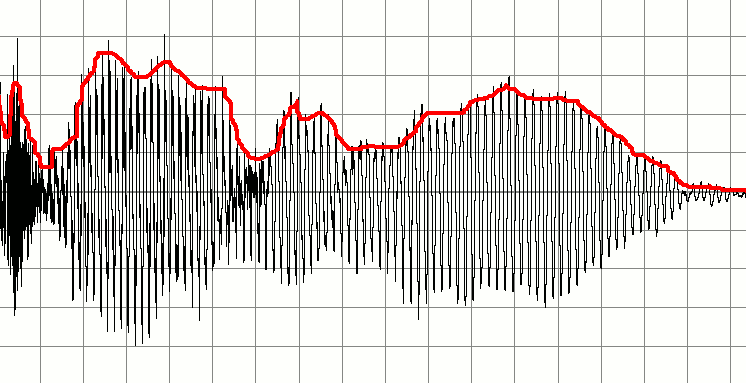
An envelope detector (sometimes called a peak detector) is an electronic circuit that takes a (relatively) high-frequency signal as input and outputs the envelope of the original signal.
Diode detector
[edit]

A simple form of envelope detector used in radio detectors is the diode detector. Its output approximates a voltage-shifted version of the input's upper envelope. Between the circuit's input and output is a forward biased diode that performs half-wave rectification, allowing substantial current flow only when the input voltage is around a diode drop higher than the output terminal. Since speech and music have approximately equal positive and negative voltage amplitude ranges, the capacitor only needs to charge up to the peak value. The RC time constant is chosen to prevent a too rapid or a too slow discharge.[1]
The output is connected to a capacitor of value and resistor of value in parallel to ground. The capacitor is charged as the input voltage approaches its positive peaks. At other times, the capacitor is gradually discharged through the resistor. The resistor and capacitor form a 1st-order low pass filter, which attenuates higher frequencies at a rate of -6 dB per octave above its cutoff frequency of . The filter's RC time constant must be small enough to track quickly-falling envelope slopes and "top up" the envelope's voltage every peak to prevent negative peak clipping.[2]


AM demodulation
[edit]Envelope detectors can be used to demodulate an amplitude modulated (AM) signal. Such a device is often used to demodulate AM radio signals because the envelope of the modulated signal is equivalent to the baseband signal. To sufficiently attenuate the frequency of the carrier wave frequency , the cutoff frequency of the low-pass filter should be well-below the carrier wave's frequency. To avoid negative peak clipping, the original signal that is modulated is usually limited to a maximum frequency to limit the maximum rate of fall of the AM signal. To minimize distortions from both ripple and negative peak clipping, the following inequality should be observed:[2]


Next, to filter out the DC component, the output could pass through a simple high-pass filter, such as a DC-blocking capacitor.
General considerations
[edit]Most practical envelope detectors use either half-wave or full-wave rectification of the signal to convert the AC audio input into a pulsed DC signal. Full-wave rectification traces both positive and negative peaks of the envelope. Half-wave rectification ignores negative peaks, which may be acceptable based on the application, particularly if the input signal is symmetric about the horizontal axis. Low threshold voltage diodes (e.g. germanium or Schottky diodes) may be preferable for tracking very small envelopes.
The filtering for smoothing the final result is rarely perfect and some "ripple" is likely to remain on the output, particularly for low frequency inputs such from a bass instrument. Reducing the filter cutoff frequency gives a smoother output, but designers must compromise this with the circuit's high frequency response.
Definition of the envelope
[edit]
Any AM or FM signal can be written in the following form


In the case of AM, φ(t) (the phase component of the signal) is constant and can be ignored. In AM, the carrier frequency is also constant. Thus, all the information in the AM signal is in R(t). R(t) is called the envelope of the signal. Hence an AM signal is given by the function


with m(t) representing the original audio frequency message, C the carrier amplitude and R(t) equal to C + m(t). So, if the envelope of the AM signal can be extracted, the original message can be recovered.
In the case of FM, the transmitted has a constant envelope R(t) = R and can be ignored. However, many FM receivers measure the envelope anyway for received signal strength indication.
Precision detector
[edit]An envelope detector can also be constructed using a precision rectifier feeding into a low-pass filter.
Drawbacks
[edit]The envelope detector has several drawbacks:
- The input to the detector must be band-pass filtered around the desired signal, or else the detector will simultaneously demodulate several signals. The filtering can be done with a tunable filter or, more practically, a superheterodyne receiver
- It is more susceptible to noise than a product detector
- If the signal is overmodulated (i.e. modulation index > 1), distortion will occur
Most of these drawbacks are relatively minor and are usually acceptable tradeoffs for the simplicity and low cost of using an envelope detector.
Audio
[edit]An envelope detector is sometimes referred to as an envelope follower in musical environments. It is still used to detect the amplitude variations of an incoming signal to produce a control signal that resembles those variations. However, in this case the input signal is made up of audible frequencies.
Envelope detectors are often a component of other circuits, such as a compressor or an auto-wah or envelope-followed filter. In these circuits, the envelope follower is part of what is known as the "side chain", a circuit which describes some characteristic of the input, in this case its volume.
Both expanders and compressors use the envelope's output voltage to control the gain of an amplifier. Auto-wah uses the voltage to control the cutoff frequency of a filter. The voltage-controlled filter of an analog synthesizer is a similar circuit.
Modern envelope followers can be implemented:
- directly as electronic hardware,
- or as software using either a digital signal processor (DSP) or
- on a general-purpose CPU.
See also
[edit]References
[edit]- ^ a b Gibson, Jerry (1993). Principles of Digital and Analog Communications. New York: Macmillan Publishing Company. pp. 111–112. ISBN 0023418605.
- ^ a b Lesurf, Jim (2000-05-18). "The Envelope Detector". www.winlab.rutgers.edu. Archived from the original on 2023-03-26. Retrieved 2024-06-09.
External links
[edit]Envelope detector
View on GrokipediaFundamentals
Definition and Purpose
An envelope detector is a fundamental electronic circuit designed to extract the modulating signal, or envelope, from an amplitude-modulated (AM) carrier wave through a process of rectification followed by low-pass filtering. This approach traces the amplitude variations of the high-frequency carrier, effectively isolating the low-frequency message embedded within it.[4][5] The input to an envelope detector is typically a high-frequency modulated waveform, where the carrier signal's amplitude is varied in accordance with the low-frequency message, such as audio for broadcasting or data in communication systems, forming an outline that represents the original information.[4] In communication systems, the primary purpose of the envelope detector is to demodulate AM signals and recover the baseband audio or data without requiring a local oscillator or phase synchronization, in contrast to coherent detection methods that demand precise carrier recovery. This simplicity makes it ideal for straightforward receivers, enabling efficient signal recovery in applications like AM radio broadcasting.[4] Historically, envelope detection emerged in the early 20th century as a key technology for AM radio receivers, with Reginald Fessenden's pioneering work around 1901 in developing continuous-wave AM transmission and associated detectors, such as his electrolytic barretter, helping to popularize the technique.[6] By the 1920s, envelope detectors, often implemented via crystal diodes, saw widespread commercial use in simple crystal radio sets, facilitating accessible home radio reception without external power sources.[7]Mathematical Envelope
In signal processing, the envelope of a modulated signal is formally defined as the magnitude of its analytic representation. For a narrowband signal expressed as , where is the slowly varying amplitude, is the carrier angular frequency, and is the phase, the envelope is .[8] This definition captures the instantaneous amplitude variation that bounds the signal's oscillations in the time domain. For amplitude modulation (AM) specifically, the transmitted signal takes the form , where is the constant carrier amplitude and is the message signal satisfying to avoid overmodulation. Under this condition, the envelope simplifies to , which directly encodes the message information and remains non-negative.[9] The envelope can be rigorously extracted using the Hilbert transform, which generates the analytic signal. The Hilbert transform of is defined as the convolution , equivalent to passing through an all-pass filter with a phase shift for positive frequencies and for negative frequencies. The analytic signal is then , which suppresses negative frequency components and doubles the positive ones in the frequency domain, yielding for and for . The envelope follows as .[8][9] This envelope concept focuses solely on amplitude, disregarding instantaneous frequency or phase variations . In AM, the envelope varies with the message, enabling straightforward recovery, whereas in frequency modulation (FM), the envelope remains constant at the carrier amplitude since modulation affects only the phase or frequency.[10]Basic Circuit Operation
Diode Detector Circuit
The diode detector circuit represents the simplest hardware implementation of an envelope detector, consisting of a single diode in series with the input radio frequency (RF) signal, followed by a parallel RC network where the resistor connects to ground and the capacitor spans the load.[1] A fast-switching silicon diode suitable for RF applications up to several hundred MHz may be used.[11] The input RF signal connects to the diode's anode, with the cathode linking to one terminal of the capacitor and resistor; the output is taken across the capacitor.[12] The diode serves as a half-wave rectifier, conducting only during the positive half-cycles of the input signal when the input voltage exceeds the capacitor's voltage, thereby allowing charge to flow into the capacitor.[1] This unidirectional conduction prevents the capacitor from discharging back through the input during negative cycles, effectively isolating the positive peaks of the carrier waveform.[13] The RC network functions as a low-pass filter to smooth the rectified waveform, with the capacitor storing charge from the diode's conduction periods and the resistor providing a discharge path.[12] The time constant governs the discharge rate, typically selected such that is much larger than the carrier period but smaller than the modulation period to follow amplitude variations without excessive ripple.[1] In basic operation, an input sinusoid results in an output waveform that tracks the peaks of the input, exhibiting an exponential decay between consecutive positive cycles as the capacitor discharges through the resistor.[12] This produces a smoothed approximation of the signal's upper envelope, with minor ripple dependent on the RC time constant.[1]Half-Wave Rectification Process
In the half-wave rectification process of a basic envelope detector, the diode acts as a one-way valve for the incoming amplitude-modulated (AM) signal, which consists of a carrier wave modulated by the message signal . During the positive half-cycles of the carrier, when the input voltage exceeds the diode's forward threshold, the diode becomes forward-biased and conducts, allowing current to flow and charge the capacitor to the peak of the modulated carrier waveform.[1] On the negative half-cycles, the diode reverse-biases, blocking current flow and preventing the capacitor from discharging through the input signal path.[14] The capacitor then maintains the peak voltage, slowly discharging through the parallel resistor to track the envelope's decay when the modulation decreases, effectively following the variations in , where is the carrier amplitude.[1] The rectified output waveform exhibits a series of "humps" corresponding to the positive peaks of the carrier, which are smoothed by the capacitor's action to approximate the original message signal .[1] This smoothing reduces the high-frequency carrier components, leaving a ripple at the carrier frequency rate, typically on the order of the carrier period , where is the carrier frequency.[14] The ripple amplitude depends on the RC time constant, with smaller ripples achieved when the discharge is tuned to follow modulation changes without excessive distortion.[1] A key limitation arises from the diode's forward voltage drop , which introduces a threshold effect that distorts small-amplitude signals by clipping peaks below . For standard silicon diodes, is approximately 0.7 V, reducing the output fidelity for low-level modulations in AM detection.[14] To mitigate this, low-drop Schottky diodes are often employed, offering in the range of 0.2–0.3 V, which preserves more of the envelope for weak signals without significant additional circuitry.[15] The output voltage during conduction can be approximated as: where conduction occurs when the input exceeds the capacitor voltage plus .[14] This approximation holds for the positive envelope extraction, with the reverse-bias periods ensuring isolation from negative excursions.[1]AM Demodulation
Signal Recovery Mechanism
The envelope detector recovers the original modulating signal from an amplitude-modulated (AM) carrier signal by following the positive envelope of the modulated waveform, which takes the form , where is the carrier amplitude, is the modulation index, and is the normalized message signal with . This tracing process, typically implemented via half-wave rectification, extracts the amplitude variations while suppressing the high-frequency carrier oscillations. After rectification and low-pass filtering, a DC blocking stage removes the constant component, yielding an output proportional to .[9] A key prerequisite for accurate recovery is that the modulation index satisfies , ensuring the envelope remains positive and avoiding overmodulation, which would cause phase reversals and introduce severe distortion in the recovered signal. Additionally, the carrier frequency must greatly exceed the message bandwidth (i.e., ), enabling the detector's low-pass filter to pass the baseband signal while attenuating the carrier; the detector's bandwidth is designed to match for optimal performance. These conditions guarantee that the envelope closely represents the modulating waveform without significant carrier interference.[16][17] The output processing involves a high-pass filter following the low-pass stage to eliminate the DC offset , directly producing the recovered scaled by . A simple block diagram of the signal recovery process is as follows:AM Input Signal Rectifier Low-Pass Filter High-Pass Filter Recovered m(t)
[A_c (1 + μ m(t)) → |x| → (smoothing) → (DC block) →
cos(ω_c t)] (bandwidth B) ↑
AM Input Signal          Rectifier          Low-Pass Filter       High-Pass Filter       Recovered m(t)
    [A_c (1 + μ m(t))     →   |x|             →    (smoothing)        →   (DC block)          →
     cos(ω_c t)]                                      (bandwidth B)                        ↑
RC Filtering Role
The RC filter in an envelope detector functions as a low-pass filter that attenuates the high-frequency carrier components following rectification, allowing the lower-frequency modulating signal to pass through with minimal distortion. This first-order filter exhibits a roll-off of -6 dB per octave beyond its cutoff frequency, defined as , where is the resistance and is the capacitance.[20] The design of the RC network hinges on selecting an appropriate time constant to balance rapid charging during positive carrier cycles and gradual discharge to track the modulating signal . Specifically, ensures fast charging relative to the carrier period, while allows the filter to follow variations in the modulation bandwidth without excessive lag, where is the carrier frequency.[21] For typical AM radio applications with MHz and kHz, values such as k and F yield ms, satisfying s ms.[22] Ripple in the output arises from the capacitor's partial discharge between carrier peaks, with the peak-to-peak ripple approximated as , where is the output load current drawn through . The discharge behavior during these intervals follows the exponential equation , where is the peak rectified voltage and is the time since the last peak.[23] Key trade-offs in selection impact signal fidelity: an excessively small leads to rapid discharge and high ripple that overloads subsequent stages, while an overly large prevents the output from tracking decreases in the envelope, resulting in distortion such as diagonal clipping.[24][23]Advanced Variants
Precision Rectifier Design
The precision rectifier enhances the basic envelope detector by employing an operational amplifier (op-amp) to create an ideal diode configuration, often referred to as a super diode, which overcomes the forward voltage drop inherent in standard semiconductor diodes. In this design, the input signal is applied to the non-inverting terminal of the op-amp, while the inverting terminal connects to the cathode of a diode in the feedback loop, with the diode's anode connected to the op-amp output; the rectified output is taken from the inverting terminal. For positive input voltages, the op-amp drives the output to forward-bias the diode, maintaining virtual short between inputs and producing an output equal to the input voltage. For negative inputs, the diode reverse-biases, opening the feedback loop and driving the output to zero, effectively blocking the negative half-cycle. This rectified signal then passes through an RC low-pass filter to extract the envelope, smoothing the output while attenuating the carrier frequency.[25][26] A common implementation uses a low-power op-amp such as the LM358, paired with a fast-switching diode like the 1N4148, along with resistors (e.g., 10 kΩ) for feedback stability and an RC filter (e.g., 1 kΩ resistor and 0.1 μF capacitor) tuned to the modulation bandwidth. The negative feedback loop compensates for the diode's 0.6–0.7 V threshold by amplifying the output sufficiently to maintain the input-output relationship, ensuring linearity even for signals below this threshold—unlike simple diode detectors, which fail to rectify low-amplitude inputs due to insufficient forward bias.[26][27] The ideal transfer characteristic of this half-wave precision rectifier is given by: In practice, gain can be adjusted by incorporating resistors in the feedback path (e.g., for the conducting half-cycle), allowing amplification for weak signals. Full-wave operation is achievable by combining two such circuits—one inverting the input for the negative half—but this extends beyond basic half-wave enhancement. The design's zero effective threshold voltage provides superior accuracy and reduced distortion for low-level signals, such as those in modern low-power RF receivers where input amplitudes fall below 0.7 V, enabling reliable envelope detection without additional biasing.[27][28][29]Full-Wave Detection
Full-wave envelope detectors enhance AM demodulation by rectifying both the positive and negative cycles of the carrier wave, thereby improving efficiency and reducing output ripple compared to half-wave designs.[30] Two primary passive design variants exist: the center-tapped transformer configuration, which employs a transformer with a center-tapped secondary winding and two diodes to direct current from each half-cycle through the load; and the bridge rectifier configuration, which uses four diodes arranged in a closed-loop bridge to rectify both halves without requiring a special transformer.[31] In both variants, the rectified output exhibits a ripple frequency that is double the carrier frequency (2f_c), as each carrier cycle contributes two pulses to the DC output.[31] The detection process begins with the AM input signal applied across the rectifier, where both half-cycles are converted to unidirectional pulses and combined at the output. An RC low-pass filter then smooths these pulses, following the modulation envelope at the elevated rate of 2f_c, which halves the ripple amplitude relative to a half-wave detector operating at f_c.[30] This results in a cleaner recovered audio signal with less distortion from carrier breakthrough. The ripple voltage in a full-wave envelope detector can be approximated as: where is the peak amplitude of the rectified signal, is the carrier frequency, and is the filter time constant.[31] This formulation highlights the reduced ripple due to the doubled rectification frequency, enabling smaller filter components for equivalent smoothing. Full-wave detectors achieve a theoretical maximum efficiency of approximately 81%, significantly higher than the 40.6% of half-wave detectors, as they utilize the full AC input power by processing both cycles.[32] This efficiency gain translates to higher output voltage and greater sensitivity, making full-wave designs particularly advantageous in battery-powered AM radios where power conservation and signal fidelity are critical.[30]Design Factors
Time Constant Selection
The time constant τ in an envelope detector, defined as τ = RC where R is the load resistor and C is the filter capacitor, must be carefully selected to ensure effective demodulation of the amplitude-modulated signal. The primary guideline is to choose τ such that 1/f_c ≪ τ ≪ 1/B, where f_c is the carrier frequency and B is the message signal bandwidth; this allows the capacitor to charge rapidly to follow the carrier peaks while discharging slowly enough to track the modulating envelope without excessive ripple or lag.[1] For broadcast AM signals with f_c = 550 kHz and B = 5 kHz, a suitable τ ranges approximately from 0.1 to 1 ms, balancing the need to suppress carrier harmonics and preserve audio fidelity.[1] The frequency response of the RC low-pass filter in the detector is characterized by its -3 dB cutoff frequency f_{3dB} = 1/(2πτ), which should be positioned above B to pass the message spectrum with minimal attenuation but well below f_c to attenuate residual carrier components and reduce ripple. In a Bode plot representation, the magnitude response exhibits a flat passband up to f_{3dB} followed by a -20 dB/decade roll-off, ensuring the carrier at f_c experiences significant suppression (typically >40 dB) while the message frequencies experience less than 3 dB loss. This configuration maintains the detector's ability to recover the envelope accurately across the signal bandwidth.[22] Practical implementation often involves an adjustable resistor R to tune the bandwidth dynamically, accommodating variations in carrier or message frequencies during operation. Verification of the design can be performed using circuit simulation tools such as SPICE, which model the transient response and frequency characteristics to confirm optimal τ values under realistic conditions including diode non-idealities.[1] Improper τ selection leads to distortion: if τ is too small, the capacitor discharges too quickly, resulting in excessive ripple that introduces carrier components and distortion into the recovered signal. Conversely, if τ is too large, the output lags behind decreasing portions of the envelope, resulting in "diagonal clipping" where the capacitor fails to discharge sufficiently to reach the true envelope minima promptly, smearing fast modulation transitions and attenuating high-frequency message components. A brief reference to ripple effects from the RC filter underscores the need for this balance, as excessive ripple can further degrade signal quality if not adequately managed.[1]Diode and Component Choices
In envelope detectors, the choice of diode is critical for minimizing distortion and accommodating varying signal levels, particularly in radio frequency (RF) applications. Germanium diodes, such as the 1N34A, feature a low forward voltage drop of approximately 0.3 V, enabling better sensitivity to weak signals in vintage radio receivers.[5] Schottky diodes, like the BAT54 series, provide fast switching speeds and an even lower forward voltage drop of around 0.2–0.3 V, making them suitable for high-frequency RF envelope detection where rapid response reduces distortion.[33] In comparison, silicon diodes, such as the 1N4148, exhibit a higher forward voltage drop of about 0.7 V but offer greater availability and lower cost, serving as a reliable option for general-purpose circuits despite slightly reduced sensitivity for low-amplitude signals.[5] Supporting components must also be selected to maintain signal integrity. The filter capacitor requires low equivalent series resistance (ESR) to achieve high cutoff frequencies without introducing excessive losses; ceramic or tantalum types are preferred in RF designs for their minimal ESR and stability at elevated frequencies.[34] The discharge resistor, often a carbon film type, ensures thermal and value stability over time, preventing drift in the time constant.[35] For enhanced RF isolation from the output load, an RF choke inductor can be incorporated in series with the load, blocking high-frequency components while passing the demodulated envelope.[36] Key considerations include the diode's reverse leakage current, which should be kept below 1 nA to avoid unintended discharge of the filter capacitor during reverse-biased periods, thereby preserving the envelope accuracy.[37] Additionally, temperature variations affect the forward voltage drop, with a typical negative coefficient of -2 mV/°C for silicon diodes, necessitating compensation in precision applications to mitigate distortion from thermal changes.[38] Trade-offs between cost and performance are evident in component selection. A basic silicon diode like the 1N4148 costs approximately $0.01 in bulk quantities, enabling economical implementations for simple detectors.[39] In contrast, a precision rectifier variant using an operational amplifier, such as the LM358, along with supporting components, incurs a total cost of around $1, offering superior linearity and reduced diode drop effects at the expense of simplicity.Applications
Radio Signal Processing
In traditional radio systems, the envelope detector plays a central role in amplitude modulation (AM) demodulation within superheterodyne receivers, where it is typically employed after the intermediate frequency (IF) amplification stage to recover the baseband audio signal from the modulated carrier. This configuration is standard in AM broadcast receivers operating in the medium wave band of 530-1700 kHz, where the detector extracts the envelope of the IF signal—typically at 455 kHz—by rectifying the carrier and low-pass filtering the result to isolate the modulating signal.[5][40][41] Historically, envelope detection evolved from early crystal sets in the 1900s, which used simple crystal detectors like galena or carborundum to rectify weak AM signals without external power, enabling basic wireless reception during the nascent era of radio broadcasting. By the 1920s and 1930s, vacuum tube-based detectors in tuned radio frequency (TRF) and superheterodyne designs improved sensitivity and selectivity, with the superhet architecture—patented by Edwin Armstrong in 1918—solidifying the envelope detector's position post-IF for widespread commercial use. The transition to semiconductor diodes in the 1950s and integrated circuits (ICs) from the 1970s onward miniaturized these detectors, incorporating them into portable radios and enhancing reliability through silicon components.[42][43][5] Envelope detectors are often integrated with automatic gain control (AGC) circuits in these receivers to maintain consistent audio output across varying signal strengths, where the detector's output provides a DC voltage proportional to the signal amplitude that biases earlier amplifier stages to prevent overload or distortion. This combination is evident in applications like walkie-talkies and shortwave radios, where AGC ensures stable reception in dynamic environments such as mobile communications or amateur radio bands. In modern extensions, software-defined radio (SDR) platforms implement digital envelope detection using the Hilbert transform in digital signal processing (DSP) to compute the analytic signal and extract the envelope, offering flexibility for real-time analysis. Such DSP-based methods are particularly suited for low-power IoT sensors employing AM modulation, enabling efficient demodulation in battery-constrained devices for applications like remote monitoring.[44][45][46]Audio Envelope Following
In audio engineering, envelope followers play a crucial role in music production by extracting the amplitude envelope of an incoming audio signal and converting it into a control voltage (CV) or modulation signal that drives dynamic effects and synthesis parameters. This process allows musicians to create responsive, expressive sounds where the intensity of playing influences the processing, such as modulating filter sweeps or volume levels in real time. For instance, in compressors, the envelope follower detects signal amplitude to determine gain reduction ratios, enabling automatic dynamic control that mimics natural acoustic behaviors.[47][48] Key applications include auto-wah pedals, where the envelope drives a filter's frequency response to produce a quack-like sweep triggered by note attack, and ADSR (attack, decay, sustain, release) envelope generators in synthesizers, which use the follower to shape oscillator or filter contours based on input dynamics. In digital audio workstations (DAWs) like Ableton Live, the Envelope Follower device captures audio amplitude changes and maps them to parameters such as reverb decay or delay feedback, facilitating creative modulation in post-production and live performance. These tools extend to modern effects processing, where envelope following enhances rhythmic gating or sidechain compression in electronic music genres.[49][50][51] Analog implementations typically employ a diode-based rectifier followed by an RC low-pass filter to smooth the detected envelope, providing a simple yet effective circuit for guitar effects pedals that respond instantaneously to plucking dynamics. A seminal example is the 1972 Mu-Tron III pedal by Musitronics, which integrated an envelope follower with a state-variable filter to pioneer auto-wah sounds in funk and rock basslines, influencing artists like Bootsy Collins. Digitally, envelope followers use peak detection or Hilbert transform algorithms, often sampling at 44.1 kHz to match standard audio rates, with low-pass filtering to reduce ripple while preserving transient response for synthesis applications. In DAWs, these run as plugins, enabling precise control over attack and release times for nuanced modulation.[52][53][54]Limitations
Performance Drawbacks
Envelope detectors, particularly those using simple diode implementations, suffer from distortions arising from the non-linear characteristics of the diode. The diode's exponential I-V relationship introduces harmonic distortion in the demodulated output, with typical total harmonic distortion (THD) values ranging from 5% to 10% for a modulation index of 30%. For a modulation index of 0.5, THD is generally around 1-5%, depending on the diode type and circuit design. Additionally, at low signal amplitudes below the diode's forward threshold voltage—typically 0.6-0.7 V for silicon diodes—the detector experiences threshold loss, where the diode fails to conduct effectively, resulting in attenuated or lost signal components.[55][56] Ripple and noise issues further degrade performance when the RC time constant τ is improperly selected. If τ is too small relative to the carrier period, the capacitor discharges excessively between peaks, allowing carrier breakthrough and introducing ripple at the carrier frequency into the output envelope. This manifests as unwanted high-frequency components superimposed on the demodulated signal. In weak signal environments, SNR degrades significantly due to the diode's shot noise and the threshold effect, which amplifies noise relative to the signal and reduces detection sensitivity for inputs near or below the noise floor.[1] Bandwidth limitations restrict the suitability of envelope detectors for wideband signals or those with high modulation depth. The RC filter's response cannot accurately track rapid envelope variations in wideband modulation without either excessive ripple (if τ is small) or diagonal clipping (if τ is large), leading to poor fidelity. For high modulation depths approaching or exceeding 100%, distortion intensifies, and overmodulation (μ > 1) causes carrier phase reversals where the modulating signal crosses zero, inverting the detected envelope and producing severe nonlinear distortion.[5] In terms of noise performance, the figure of merit for AM envelope detection is 1/3, meaning the output SNR is one-third that of an equivalent baseband system under high carrier-to-noise conditions. These characteristics render simple diode envelope detectors outdated for post-2020 high-speed applications, such as mmWave communications, where coherent or digital detection methods offer superior bandwidth handling and lower distortion.[57]Alternatives and Comparisons
Synchronous detection, also known as coherent demodulation, employs a local oscillator phase-locked to the incoming carrier frequency to multiply with the received signal, enabling precise recovery of the modulating waveform. Unlike envelope detectors, it eliminates the threshold effect—where performance degrades sharply below approximately 10 dB SNR—maintaining consistent output even in low-SNR environments. Additionally, synchronous detection provides a 3 dB SNR improvement over envelope detection in high-SNR conditions due to its coherent processing, though it demands accurate phase synchronization, which can introduce complexity in implementation.[58][59][60] The product detector, a specific form of synchronous detector, multiplies the modulated signal by a recreated carrier to extract the baseband information, making it particularly suitable for single-sideband (SSB) suppressed-carrier signals. It exhibits lower distortion than envelope detection, especially at high modulation depths exceeding 80%, as it avoids nonlinear rectification artifacts that plague diode-based envelope methods. This results in clearer audio recovery for voice communications, with reduced intermodulation products in the output.[58][61] Digital alternatives leverage digital signal processing (DSP) for envelope extraction, often using the Hilbert transform to compute the analytic signal and derive the magnitude envelope, or fast Fourier transform (FFT) for frequency-domain analysis. These methods offer superior accuracy and adaptability compared to analog envelope detectors, avoiding hardware-specific limitations like diode nonlinearity. FPGA implementations of DSP-based envelope detection provide advantages in processing speed, power consumption, and reconfigurability for varying bandwidths.[54][62][63]| Technique | Simplicity | Cost | Distortion Level | Applicability |
|---|---|---|---|---|
| Envelope Detection | High | Low | Higher (threshold effect, nonlinear) | Narrowband AM, simple receivers |
| Synchronous Detection | Medium | Medium | Low | AM/SSB in noisy environments, coherent systems |
| Product Detector | Medium | Medium | Very Low | SSB, high-modulation-depth AM |
| Digital DSP (e.g., Hilbert/FPGA) | Low | High initial | Very Low | 5G IoT, broadband digital modems |