Hubbry Logo
Beam axleBeam axleMain
Open search
Beam axle
Community hub
Beam axle
logo
8 pages, 0 posts
0 subscribers
Be the first to start a discussion here.
Beam axle
Beam axle
from Wikipedia
Diagonal Panhard rod bolted to a black rectangular profile beam axle on a front-wheel-drive 2002 Mazda MPV. This is an example of a "dead axle". A "live axle" not only connects two wheels, but also drives them.

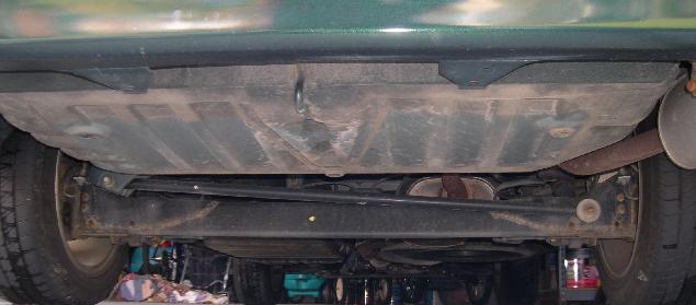
A beam axle, rigid axle, or solid axle is a dependent suspension design in which a set of wheels is connected laterally by a single beam or shaft. Beam axles were once commonly used at the rear wheels of a vehicle, but historically, they have also been used as front axles. In most automobiles, beam axles have been replaced with front (IFS) and rear independent suspensions (IRS).

Implementation

[edit]
Solid axle suspension characteristics: Camber change on bumps, none on rebound, large unsprung weight

With a beam axle, the camber angle between the wheels is the same regardless of its location in the travel of the suspension.

A beam axle's location in the fore and aft directions is constrained by one of several suspension components, including trailing arms, semi-trailing arms, radius rods, and leaf springs. The lateral location can be constrained by a Panhard rod, a Scott Russell linkage, a Watt's linkage, or some other arrangement, most commonly by the leaf springs. Shock absorbers and either leaf springs, coil springs, or air bags are used to control vertical movement.

Live axle vs dead axle

[edit]
A live axle in a Jeep. This is the front suspension, using coil springs.

A live axle is a type of beam axle in which the shaft (or, commonly, shafts connected to move as a single unit) also transmits power to the wheels; a beam axle that does not also transmit power is sometimes called a dead axle. While typically used in vehicles with Hotchkiss drive, this suspension system can also be used with other types of power transmission.

Advantages

[edit]
  • A beam axle is typically simple in design, rugged, and inexpensive to manufacture.
    • Only one universal joint or constant-velocity joint (CV) is needed at each steered and driven wheel and none are needed at non-steered wheels; this reduces maintenance requirements and manufacturing costs compared to independent suspensions, which typically require two such joints at each driven wheel.
    • The CVs are located in metal enclosures attached to the axle housings; there are no rubber CV boots that may be cut or punctured when off-roading.
  • A beam axle is space-efficient, an important advantage for off-road applications, as it provides better vehicle articulation and durability in a high-load environment.
  • Camber angle is rigidly fixed by axle geometry; for a live axle, toe is typically fixed as well.
    • As the vehicle's body rolls during hard cornering, the unchanging camber yields predictable handling—at least on smooth surfaces.
    • Wheel alignment is simplified.
    • Traction, braking and tire wear characteristics do not change as the suspension is compressed. These are great benefits in a vehicle that carries heavy loads, and together with the beam axle's characteristic strength, this has resulted in front and rear beam axles being nearly universal in buses and heavy-duty trucks. Most light- and medium-duty pickup trucks, SUVs, and vans also use a beam axle, at least in the rear.
  • A beam axle is easier and less expensive to modify than other axles. This is because it has fewer parts, less mechanical complexity, and more empty space between suspension components, axles, and the vehicle's frame or body. This makes it easier to work with when making modifications such as adding lift kits to increase body or running clearance, or installing larger diameter tires to increase ground/axle clearance.[1]

Disadvantages

[edit]
  • A beam axle does not allow each wheel to move independently in response to uneven surfaces, which can lead to adverse vibration and worse handling than more sophisticated suspension designs.
    • In turns, the outside wheel is subjected to negative camber angles when the inside wheel hits a bump, which can suddenly reduce or increase cornering grip and destabilize the vehicle.
    • Toe is typically fixed at zero for a live axle, and dynamic toe control is difficult to implement.
  • The mass of the beam is part of the unsprung weight of the vehicle, hurting ride quality.
    • The need for lateral location devices such as a Panhard rod or Watt's linkage adds more unsprung weight and partially offsets the beam axle's advantages in terms of simplicity, space efficiency, and cost.
  • In a vehicle with conventional Hotchkiss drive, the entire axle may twist in its mounts in reaction to torque loads; during hard acceleration, this may reduce traction and induce wheel hop or sudden adverse toe changes.
  • The bulky differential housing of a Hotchkiss live axle reduces ground clearance, hindering the vehicle's ability to ford deep mud, clear obstacles and negotiate deeply rutted roads.
    • The differential housing can only be raised by using larger wheels and tires, typically with a penalty in unsprung weight, braking effectiveness and acquisition costs; furthermore, vehicle modifications may be necessary for adequate fender or frame clearance.
  • Front beam axle suspension is unusually sensitive to any lack of concentricity in the hub and wheel assembly which can cause a side-to-side oscillation ("shimmy") of the steering at certain speeds (typically 60–80 km/h; 40–50 mph), commonly referred to as "death wobble" within the 4×4 community.[2] This is addressed on some vehicles with steering dampers, although removal and careful refitting of the front wheels often resolves the problem.
  • The axles and supporting hardware take up more room underneath the vehicle compared to independent suspension, this leaves less room for people and cargo without having an excessively tall vehicle.[3]Which is more likely to roll over due to high center of gravity, if vehicle width is not increased.

Axle truss

[edit]

An axle truss is typically a six-millimeter thick steel plate bent into a "Π"-shaped beam and welded with the open side facing the top of the differential or axle housing. It reinforces a solid axle so that it does not bend or break when the axle's load rating is exceeded.[4] A larger/thicker axle is stronger, but also comes with increased cost, unsprung weight, and more compatibility issues (drivetrain, suspension, steering geometries, body mount locations, clearances) on smaller vehicles.[5]

eAxle

[edit]

eAxle or E-axle is a solid axle with electric motors attached to the differential, either end, or elsewhere. Inverters, power electronics, gearboxes, transfer cases (including low-range gearing), and transmissions may also be attached to the motors and/or axle. All components move with the axle as unsprung weight.[6][7][8][9]

eAxle(s) maybe used to replace dead/un-powered axles, as modifying a 6x2 into a 6x6 or 8x8 is typically very expensive and difficult, requiring numerous custom made parts, re-engineering, recertification. eAxles just need to be wired to a battery and/or electricity generator.

Examples

[edit]

See also

[edit]

Notes

[edit]
Revisions and contributorsEdit on WikipediaRead on Wikipedia
from Grokipedia
A beam axle, also known as a solid axle or rigid axle, is a type of dependent suspension system in where a single continuous beam or shaft connects a pair of wheels laterally, forcing them to move in unison relative to the vehicle's . This design contrasts with systems, as the motion of one wheel directly influences the other, transmitting forces across the axle. Typically constructed from forged steel for strength and durability, the beam axle supports the vehicle's weight, houses components like kingpins on front applications, and integrates with springs and shock absorbers to dampen impacts. The beam axle traces its origins to early horse-drawn carriages and was a standard feature in the first automobiles, such as the , where it served as both front and rear suspension in rear-wheel-drive configurations. Over time, its use evolved with advancements in materials and ; for instance, Ford's Twin I-Beam variant, introduced in 1965 for trucks, featured two parallel I-beams to improve ride quality while retaining rigidity. By the mid-20th century, beam axles began to be phased out in passenger cars in favor of independent suspensions for better handling, but they persisted in heavy-duty applications due to their inherent robustness. Beam axles excel in simplicity and load-bearing capacity, making them ideal for trucks, off-road s, and commercial fleets where they maintain consistent wheel camber under heavy payloads and provide straightforward with fewer components. However, their high unsprung contributes to harsher ride quality, as bumps on one side affect the entire , and they limit camber adjustments during cornering, potentially leading to uneven wear. Despite these drawbacks, modern variants like torsion beam axles—often used in compact front-wheel-drive cars—adapt the concept with twisting compliance for semi-independent behavior, balancing cost and performance.

Fundamentals

Definition and Components

A beam axle, also known as a solid or rigid axle, is a dependent suspension design in which a set of wheels is connected laterally by a single beam or housing, causing the wheels to move in parallel as a unit. This contrasts with systems, where each wheel operates separately. The primary structural elements of a beam axle include the axle beam, which serves as the central rigid structure typically formed as a solid bar or housing, often with an I-section in the middle for strength and circular ends to accommodate wheel attachments. At each end of the beam, wheel hubs are mounted, housing bearings that allow the wheels to rotate freely while supporting the vehicle's load. In configurations where power delivery is required, a differential housing is integrated into the beam, enclosing the differential mechanism to distribute drive torque to the wheels. Additionally, mounting points on the beam provide attachment locations for suspension components, such as leaf springs or shock absorbers, which connect the axle to the vehicle chassis. In operation, the beam axle transmits forces from the to the s through its rigid , effectively distributing vertical loads, braking forces, and—where applicable— evenly across both s due to the interconnected . This load-sharing mechanism ensures that impacts or movements at one are directly felt by the other, with the beam acting as an unsprung that influences overall suspension dynamics. A labeled of a beam axle would typically illustrate the central beam, end-mounted wheel hubs, integrated differential housing (if present), and suspension mounting points for springs and shocks, highlighting the parallel wheel movement.

Historical Development

The beam axle, a rigid solid axle design, traces its origins to 19th-century horse-drawn carriages, where it provided a simple, durable means of supporting and transmitting power from draft animals to . As industrialization advanced carriage production, this configuration became standard for its robustness on uneven roads, evolving from basic wooden axles to iron-reinforced beams that could handle heavier loads in wagons and coaches. The adaptation of the beam axle to motorized vehicles occurred with the dawn of the automobile era, notably in Karl Benz's 1885 , recognized as the first practical automobile, which featured a beam rear axle paired with elliptic springs to manage the weight of its and . This design prioritized simplicity and reliability in the nascent field of self-propelled transport. By the early , the beam axle gained widespread adoption, exemplified by the 1908 , which employed transverse semi-elliptical leaf springs mounted to both front and rear beam axles, enabling the vehicle's affordability and suitability for rudimentary roads. Throughout the 20th century, particularly up to and during , beam axles dominated in trucks and off-road vehicles due to their straightforward construction, ease of maintenance, and ability to withstand heavy loads and rough terrain. Military applications underscored this, as seen in U.S. GMC CCKW 2½-ton 6x6 trucks, which utilized three driven beam axles on leaf springs for superior cross-country mobility in combat zones. Key innovations, such as Henry Timken's 1898 patents for tapered roller bearings, enhanced beam axle performance by reducing friction and improving load capacity, leading to the formation of the Timken Roller Bearing Axle Company in 1899. Post-World War II, beam axles in passenger cars gradually yielded to systems during the 1950s and 1960s, as automakers sought improved ride comfort and handling; for instance, independent front suspension became prevalent in American luxury models by the late 1940s, while rear independent setups emerged in sports cars like the 1954 300SL. Nonetheless, beam axles persisted in heavy-duty trucks and commercial applications for their cost-effectiveness and durability under high stress. In recent developments through 2025, beam axles have seen a revival in electric vehicles, particularly through integrated "eBeam" designs that mount electric motors directly to the solid axle for simplified power delivery and reduced manufacturing costs, as demonstrated by Magna International's eBeam module introduced in 2021 for affordable EV trucks and its adoption in production models such as ' 2025 Traveler and Terra pickup.

Types and Variants

Live Axle

A live beam axle is a dependent suspension system in which a solid beam connects the wheels laterally, with the axle housing integrating the differential and axle shafts to transmit rotational power directly from the drivetrain to the wheels, enabling propulsion. This configuration distinguishes it from non-driven variants by incorporating drive components within the rigid beam structure. The mechanics of power transmission in a live beam axle begin with torque from the engine and transmission delivered via a propeller shaft, which connects to the axle's input gear through universal joints to accommodate suspension movement. The engages a hypoid ring gear in the differential, mounted at a slight offset angle less than 90 degrees, to redirect power flow perpendicularly while providing gear reduction for increased and reduced speed. Inside the differential carrier, spider gears interact with side gears on the axle shafts to split and distribute equally to both wheels under straight-line conditions, allowing speeds during turns to prevent binding. Construction of the live beam axle typically features a banjo-style housing for rear applications, characterized by a tubular beam with a central, enlarged section resembling a banjo head that houses the differential assembly, sealed by a cover plate for easy access and maintenance. This design supports the vehicle's weight and drive loads while allowing the differential to be removed without disassembling the entire housing. Hub designs vary between semi-floating, where the axle shaft bears both vehicle weight and torque via a single outer bearing, and full-floating, where dual bearings on the housing support the weight independently, with the shaft dedicated solely to torque transmission for enhanced durability under heavy loads. Live beam axles are commonly employed in rear-wheel-drive vehicles due to their robust power delivery to the rear wheels. Torque distribution follows the principle Ttotal=Tleft+TrightT_{\text{total}} = T_{\text{left}} + T_{\text{right}}, where the differential adjusts allocation based on individual wheel traction to optimize without excessive slip. Unlike dead axles that provide only , live beam axles integrate these driven elements for direct .

Dead Axle

A dead axle is a type of beam axle that does not transmit drive power from the to the wheels, functioning instead as a non-rotating rigid support structure for load-bearing and stability. It is commonly employed in front positions for purposes in rear-wheel-drive vehicles or in rear positions as a fixed support in front-wheel-drive configurations, where it connects the wheels laterally without contributing to . This design contrasts with powered alternatives by prioritizing structural integrity over delivery. Mechanically, the dead axle provides a stationary beam for and , with rotating on bearings at the ends without through the axle. Its inherent rigidity is critical for maintaining camber angles under varying loads, which helps preserve consistent contact with the road surface and supports overall handling without significant geometric changes during suspension travel. In construction, the dead axle employs a simplified beam structure lacking a differential housing, typically forged from high-grade steel into an I-beam shape and heat-treated for enhanced durability. For front applications, the beam ends incorporate stub axles attached via kingpins in older designs or ball joints in modern variants, enabling pivotal articulation for steering while distributing vehicle weight from the springs to the wheels. Dead axles were particularly common in early trucks due to their straightforward design and robust load-bearing properties.

eAxle

An eAxle represents an electrified evolution of the beam axle, integrating electric motors, inverters, and gearboxes directly into the axle structure to form a compact unit for electric vehicles (EVs). This consolidates propulsion components, enabling efficient power delivery to the wheels while maintaining the rigid beam's simplicity for load-bearing applications. In eAxle mechanics, electric motors are typically mounted centrally on the beam or as dual units flanking the differential, minimizing the need for extended driveshafts and allowing direct application to the ends. is facilitated through axle-mounted motors and , which recapture during deceleration by reversing motor operation to generate fed back to the battery. Construction of eAxles emphasizes lightweight materials, such as die-cast aluminum housings for the beam and motor enclosures, to reduce overall while ensuring structural . Integrated cooling systems, often oil-based, manage heat from the motors and electronics, preventing thermal throttling during high-load operation. In dual-motor configurations, independent control of each motor enables , where differential torque distribution enhances vehicle stability and handling by adjusting power to individual wheels. As of 2025, eAxles are gaining traction in affordable EVs, particularly in the Chinese market, where production volumes are projected to dominate global eAxle output. ZF's eBeam axle prototype, introduced in 2023, exemplifies this trend with its integrated 400-800V architecture, influencing designs in emerging hybrid and EV models. Power output in these systems follows the relation P=τ×ωP = \tau \times \omega, where PP is power, τ\tau is motor , and ω\omega is .

Design and Construction

Axle Truss

An truss is a welded or bolted triangular framework added to the underside of the to prevent or "whip" under . This structure attaches directly to the differential housing and extends along the tubes, creating a rigid support that counters the flexing of the housing when high is applied through the . The primary mechanical role of the truss is to reinforce the beam axle against torsional stresses, which arise from the twisting forces transmitted from the , particularly during or when traversing uneven . By distributing these stresses across the triangular framework, the truss minimizes deformation in the differential housing, reducing the risk of component misalignment, seal failures, or premature wear. This design is especially prevalent in modifications, where amplified and dynamic loads from rough surfaces intensify the need for such . Construction of an axle truss typically involves high-strength steel tubing, such as DOM (Drawn Over ) seamless steel, formed into diagonal and horizontal members to form the triangular shape. Installation methods include the truss plates and tubes directly to the differential housing and axle beams for a permanent, high-integrity bond, or using bolted configurations with high-grade fasteners for reversible modifications. These methods ensure the truss integrates seamlessly with the existing beam axle assembly. Axle trusses are essential for high-horsepower applications, where elevated engine output generates greater that can induce significant in the without additional support. Stress analysis for this involves the , a basic principle in expressed as M=F×dM = F \times d where MM is the , FF is the applied force, and dd is the moment arm. This calculation guides truss design to it can resist the resulting stresses effectively. As a modular addition to beam materials, the axle truss enhances structural rigidity without altering the core fabrication of the axle beam itself.

Beam Materials and Integration

Beam axles are traditionally constructed from cast iron or forged steel to ensure high durability and load-bearing capacity under demanding conditions. Cast iron provides excellent wear resistance and damping properties, making it suitable for heavy-duty applications, while forged steel offers superior tensile strength, often exceeding 65,000 psi, which enhances structural integrity. These materials have been standard in beam axle production due to their ability to withstand fatigue and impact without deformation. In contemporary designs, especially for electric vehicles, aluminum alloys are increasingly adopted to reduce overall vehicle weight, with beam components achieving 20-40% lighter profiles compared to equivalent steel versions while maintaining comparable strength through advanced alloy formulations. This shift supports improved energy efficiency and range in EVs by minimizing unsprung mass. Construction methods for beam axles typically involve casting for complex shapes, forging for high-strength monolithic beams, or welding for assembled variants, followed by heat treatment processes such as quenching and tempering to enhance fatigue resistance and achieve uniform microstructures like tempered martensite. Integration of the beam axle into the vehicle chassis occurs primarily through mounting points that connect to leaf springs, coil springs, or systems, distributing loads evenly and allowing controlled vertical travel. These connections use bushings or pivots to isolate vibrations and ensure precise alignment with steering knuckles and suspension linkages, such as radius arms or control arms, which maintain camber and angles during operation. In the , advancements in composite-reinforced beams have emerged for enhanced , incorporating carbon fiber or hybrid materials in suspension structures to further reduce weight and improve recyclability, as demonstrated in projects like the Composite Hybrid Automotive Suspension System for commercial vehicles.

Performance Characteristics

Advantages

Beam axles offer significant advantages in simplicity and cost-effectiveness compared to systems, primarily due to their fewer components and straightforward design. This mechanical simplicity reduces the number of parts required, such as eliminating multiple control arms and linkages, which facilitates easier assembly and lowers expenses. Maintenance is also simplified, as the rigid structure allows for straightforward repairs without complex alignments. In terms of durability, beam axles excel in high-load applications, making them ideal for off-road vehicles and trucks where they withstand heavy stresses and rough conditions effectively. Their robust construction supports substantial weight transfer and maintains structural integrity under demanding use, providing high load capacity for hauling and . The design ensures consistent camber angles during operation, which is particularly beneficial for heavy hauling by minimizing wear and promoting even load distribution. Additional benefits include predictable handling characteristics, with enhanced straight-line stability arising from the axle's rigid connection that resists unwanted lateral movements. Beam axles pair well with leaf-spring setups, where the springs integrate seamlessly to distribute evenly and support articulation without compromising balance.

Disadvantages

Beam axles exhibit significant handling limitations due to their rigid design, which forces both wheels to move in parallel rather than independently. This parallel motion induces , where suspension travel inadvertently alters the angle, and causes undesirable camber changes during cornering, leading to reduced tire and grip. On uneven surfaces, the lack of independent wheel articulation results in one 's vertical movement affecting the opposite side, compromising stability and traction. Ride comfort is another key drawback, as the solid beam transmits road harshness directly to the without effective isolation, amplifying vibrations and impacts. For instance, solid axles on vehicles like the Jeep Wrangler feel harsher on pavement compared to independent front suspension because they transmit road imperfections more directly, resulting in a bouncy, skittish, and harsher ride; independent front suspension allows each wheel to move independently, soaking up bumps and whoops better for improved comfort and stability. The higher unsprung mass inherent to beam axles—stemming from the entire axle assembly moving with the wheels—further exacerbates this by slowing suspension response and increasing perceived road noise and harshness. In unibody vehicle designs, beam axles prove space-inefficient, as the rigid beam requires substantial underfloor clearance and complicates integration with the integrated structure, often encroaching on interior packaging or placement. By the , these limitations led to beam axles being largely replaced by independent suspensions in most passenger cars, though they persisted in some performance models into the 2010s. In modern electric vehicles (EVs), eAxles incorporating beam designs face persistent (noise, vibration, and harshness) mitigation challenges, as the rigid structure amplifies high-frequency tonal noise from electric motors and gear meshing, lagging behind independent setups in despite ongoing advancements in 2024-2025 .

Applications and Examples

Front Axle Usage

Beam axles, also known as solid axles, are commonly employed in the front position of trucks, SUVs, and off-road vehicles where high durability under loads is essential. These axles provide a rigid connection between the wheels, enabling them to withstand the torsional forces and impacts associated with in rugged terrain. For instance, the front axle is a prominent example, featuring robust construction with 1.5-inch diameter, 35-spline axleshafts capable of supporting tires up to 44 inches in diameter, making it ideal for heavy-duty applications in off-roaders. This design's simplicity and strength allow it to handle extreme loads better than independent systems, particularly in vehicles subjected to frequent articulation and obstacle navigation. In front axle configurations, beam axles integrate with steering components such as the pitman arm, drag link, and tie rods to transmit steering input from the gear box to the wheels. The pitman arm connects to the drag link, which in turn links to the tie rods attached to steering knuckles on the axle beam, allowing pivoting via kingpins or ball joints. However, achieving precise Ackermann steering geometry—where inner and outer wheels turn at different angles to follow a common turning center—presents challenges with solid beam axles due to their fixed beam structure, often resulting in approximations rather than exact compliance, especially under high articulation. This can lead to minor tire scrub during turns, though modifications like angled steering arms help mitigate it in off-road setups. One key advantage of front beam axles in 4x4 vehicles is their contribution to superior , as the rigid design permits greater suspension travel and lift heights without the constraints of CV joints found in independent suspensions. This enhances the vehicle's ability to climb steep inclines and descend without bumper or underbody contact, providing up to 14 inches or more of ground clearance in lifted configurations. Such geometry is particularly beneficial for , where axles maintain contact and stability over uneven surfaces. Beam axles remain persistent in vehicles for their reliability in harsh environments, with designs like the ProTec Series 50 engineered to military specifications for armored platforms, ensuring performance over rough terrain while supporting heavy payloads.

Rear Axle Usage

Beam axles are primarily employed as live rear axles in rear-wheel-drive (RWD) vehicles, where they transmit propulsion torque from the drivetrain to the rear wheels while supporting the vehicle's load. This configuration is especially common in pick-up trucks, , and light commercial vehicles (LCVs), where the axle's robust design also integrates functions for enhanced durability under demanding conditions. In contrast, beam axles function as dead axles in trailers, providing structural support without transmitting power and bearing the towed load across the wheels. Mechanically, rear beam axles are mounted longitudinally beneath the vehicle, with springs clamped to the axle tubes using U-bolts to secure the suspension and distribute forces. These U-bolts ensure the leaf pack remains firmly attached to the housing, allowing vertical compliance while maintaining alignment. reaction from the is managed through attached control arms or torque arms that link the to the , counteracting rotational forces to minimize axle wrap and maintain stability during acceleration. In the rear position, beam axles offer high capacity suited to applications, with designs capable of handling up to 20,000 pounds or more in heavy-duty trucks through their rigid construction and efficient . This makes them ideal for load-bearing and propulsion in rugged environments. Beam axles remain dominant in pickup trucks, including electrified variants like the Ford F-150 hybrid models, where they support propulsion in rear configurations.

Modern Vehicle Examples

In modern vehicles, beam axles remain prevalent in off-road-oriented and heavy-duty trucks where durability and articulation are prioritized. The continues to employ solid beam axles at both the front and rear in its 2025 model, maintaining its legacy for extreme terrain capability. Similarly, the , introduced in 2022 and carried into 2025, features solid beam axles front and rear on its ladder-frame chassis to enhance ground clearance and load-carrying performance. The Jeep Gladiator pickup, in its 2025 iteration, utilizes Dana 44 solid axles front and rear, particularly in trims like the for superior off-road flex. For rear axle applications, beam axles dominate in full-size pickups. The 2025 Ford F-150 incorporates a solid rear beam axle with leaf springs, supporting its towing capacity up to 13,500 pounds. The Ram 1500, updated for 2025, retains a solid rear beam axle base despite coil-spring suspension in higher trims, enabling a maximum of 2,300 pounds. The 2024+ employs a solid rear live axle with coil springs across its lineup, marking a shift from leaf springs while preserving off-road robustness. Emerging trends show beam axles expanding into electric vehicles for simplified integration of drive motors. The Mercedes-Benz G 580 with EQ Technology, the electric G-Class entering 2025 production, features a De Dion solid rear beam axle to balance off-road articulation with electric power delivery. Similarly, the upcoming Scout Traveler and Scout Terra EVs, with production ramping in late 2025, incorporate rear e-Beam axles where electric motors mount directly to the solid beam for enhanced towing and terrain handling. These examples, alongside stalwarts like the 2025 Ford Super Duty (solid front beam axle) and Ram 2500 (solid front and rear), illustrate beam axles' enduring role in U.S. light trucks, driven by demands for cost-effective durability over independent suspension refinement.

References

Add your contribution
Related Hubs
User Avatar
No comments yet.