Hubbry Logo
SynchroSynchroMain
Open search
Synchro
Community hub
Synchro
logo
8 pages, 0 posts
0 subscribers
Be the first to start a discussion here.
Synchro
Synchro
from Wikipedia
Schematic of a synchro transducer. The complete circle represents the rotor. The solid bars represent the cores of the windings next to them. Power to the rotor is connected by slip rings and brushes, represented by the circles at the ends of the rotor winding. As shown, the rotor induces equal voltages in the 120° and 240° windings, and no voltage in the 0° winding. [Vex] does not necessarily need to be connected to the common lead of the stator star windings.
Simple two-synchro system.

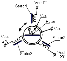
A synchro (also known as selsyn and by other brand names) is, in effect, a transformer whose primary-to-secondary coupling may be varied by physically changing the relative orientation of the two windings. Synchros are often used for measuring the angle of a rotating machine such as an antenna platform or transmitting rotation. In its general physical construction, it is much like an electric motor. The primary winding of the transformer, fixed to the rotor, is excited by an alternating current, which by electromagnetic induction causes voltages to appear between the Y-connected secondary windings fixed at 120 degrees to each other on the stator. The voltages are measured and used to determine the angle of the rotor relative to the stator.

A picture of a synchro transmitter

Uses

[edit]

Synchro systems were first used in the control system of the Panama Canal in the early 1900s to transmit lock gate and valve stem positions, and water levels, to the control desks.[1]

View of the connection diagram of a synchro transmitter

Fire-control system designs developed during World War II used synchros extensively, to transmit angular information from guns and sights to an analog fire control computer, and to transmit the desired gun position back to the gun location. Early systems just moved indicator dials, but with the advent of the amplidyne, as well as motor-driven high-powered hydraulic servos, the fire control system could directly control the positions of heavy guns.[2]

Smaller synchros are still used to remotely drive indicator gauges and as rotary position sensors for aircraft control surfaces, where the reliability of these rugged devices is needed. Digital devices such as the rotary encoder have replaced synchros in most other applications.

Selsyn motors were widely used in motion picture equipment to synchronize movie cameras and sound recording equipment, before the advent of crystal oscillators and microelectronics.

Large synchros were used on naval warships, such as destroyers, to operate the steering gear from the wheel on the bridge.

Synchro system types

[edit]

There are two types of synchro systems: torque systems and control systems.

In a torque system, a synchro will provide a low-power mechanical output sufficient to position an indicating device, actuate a sensitive switch or move light loads without power amplification. In simpler terms, a torque synchro system is a system in which the transmitted signal does the usable work. In such a system, accuracy on the order of one degree is attainable.

In a control system, a synchro will provide a voltage for conversion to torque through an amplifier and a servomotor. Control type synchros are used in applications that require large torques or high accuracy such as follow-up links and error detectors in servo, automatic control systems (such as an autopilot system). In simpler terms, a control synchro system is a system in which the transmitted signal controls a source of power which does the usable work.

Quite often, one system will perform both torque and control functions. Individual units are designed for use in either torque or control systems. Some torque units can be used as control units, but control units cannot replace torque units.[3]

Synchro functional categories

[edit]

A synchro will fall into one of eight functional categories:[4]

Torque transmitter (TX)
Input: rotor positioned mechanically or manually by the information to be transmitted.
Output: electrical output from stator identifying the rotor position supplied to a torque receiver, torque differential transmitter or a torque differential receiver.
Control transmitter (CX)
Input: same as TX.
Output: electrical output same as TX but supplied to a control transformer or control differential transmitter.
Torque differential transmitter (TDX)
Input: TX output applied to stator; rotor positioned according to amount data from TX that must be modified.
Output: electrical output from rotor (representing an angle equal to the algebraic sum or difference of rotor position angle and angular data from TX) supplied to torque receivers, another TDX, or a torque differential receiver.
Control differential transmitter (CDX)
Input: same as TDX but data supplied by CX.
Output: same as TDX but supplied to only a control transformer or another CDX.
Torque receiver (TR)
Input: Electrical angle position data from TX or TDX supplied to stator.
Output: Rotor assumes position determined by electrical input supplied.
Torque differential receiver (TDR)
Input: electrical data supplied from two TX's, two TDX's or from one TX and one TDX (one connected to the rotor and one connected to the stator).
Output: rotor assumes position equal to the algebraic sum or difference of two angular inputs.
Control transformer (CT)
Input: electrical data from CX or CDX applied to stator. Rotor positioned mechanically or manually.
Output: electrical output from rotor (proportional to sine of the difference between rotor angular position and electrical input angle).
Torque receiver-transmitter (TRX)
designed as a torque receiver, but may be used as either a transmitter or receiver.
Input: depending on the application, same as TX.
Output: depending on the application, same as TX or TR.

Operation

[edit]

On a practical level, synchros resemble motors, in that there is a rotor, stator, and a shaft. Ordinarily, slip rings and brushes connect the rotor to external power. A synchro transmitter's shaft is rotated by the mechanism that sends information, while the synchro receiver's shaft rotates a dial, or operates a light mechanical load. Single and three-phase units are common in use, and will follow the other's rotation when connected properly. One transmitter can turn several receivers; if torque is a factor, the transmitter must be physically larger to source the additional current. In a motion picture interlock system, a large motor-driven distributor can drive as many as 20 machines, sound dubbers, footage counters, and projectors.

Synchros designed for terrestrial use tend to be driven at 50 or 60 hertz (the mains frequency in most countries), while those for marine or aeronautical use tend to operate at 400 hertz (the frequency of the on-board electrical generator driven by the engines).

Single phase units have five wires: two for an exciter winding (typically line voltage) and three for the output/input. These three are bussed to the other synchros in the system, and provide the power and information to align the shafts of all the receivers. Synchro transmitters and receivers must be powered by the same branch circuit, so to speak; the mains excitation voltage sources must match in voltage and phase. The safest approach is to bus the five or six lines from transmitters and receivers at a common point. Different makes of selsyns, used in interlock systems, have different output voltages. In all cases, three-phase systems will handle more power and operate a bit more smoothly. The excitation is often 208/240-V 3-phase mains power. Many synchros operate on 30 to 60 V AC also.

Synchro transmitters are as described, but 50- and 60-Hz synchro receivers require rotary dampers to keep their shafts from oscillating when not loaded (as with dials) or lightly loaded in high-accuracy applications.

A different type of receiver, called a control transformer (CT), is part of a position servo that includes a servo amplifier and servo motor. The motor is geared to the CT rotor, and when the transmitter's rotor moves, the servo motor turns the CT's rotor and the mechanical load to match the new position. CTs have high-impedance stators and draw much less current than ordinary synchro receivers when not correctly positioned.

Synchro transmitters can also feed synchro to digital converters, which provide a digital representation of the shaft angle.

Synchro variants

[edit]

So-called brushless synchros use rotary transformers (that have no magnetic interaction with the usual rotor and stator) to feed power to the rotor. These transformers have stationary primaries, and rotating secondaries. The secondary is somewhat like a spool wound with magnet wire, the axis of the spool concentric with the rotor's axis. The "spool" is the secondary winding's core, its flanges are the poles, and its coupling does not vary significantly with rotor position. The primary winding is similar, surrounded by its magnetic core, and its end pieces are like thick washers. The holes in those end pieces align with the rotating secondary poles.

For high accuracy in gun fire control and aerospace work, so called multi-speed synchro data links were used. For instance, a two-speed link had two transmitters, one rotating for one turn over the full range (such as a gun's bearing), while the other rotated one turn for every 10 degrees of bearing. The latter was called a 36-speed synchro. Of course, the gear trains were made accordingly. At the receiver, the magnitude of the 1X channel's error determined whether the "fast" channel was to be used instead. A small 1X error meant that the 36x channel's data was unambiguous. Once the receiver servo settled, the fine channel normally retained control.

For very critical applications, three-speed synchro systems have been used.

So called multispeed synchros have stators with many poles, so that their output voltages go through several cycles for one physical revolution. For two-speed systems, these do not require gearing between the shafts.

Differential synchros are another category. They have three-lead rotors and stators like the stator described above, and can be transmitters or receivers. A differential transmitter is connected between a synchro transmitter and a receiver, and its shaft's position adds to (or subtracts from, depending upon definition) the angle defined by the transmitter. A differential receiver is connected between two transmitters, and shows the sum (or difference, again as defined) between the shaft positions of the two transmitters. There are synchro-like devices called transolvers, somewhat like differential synchros, but with three-lead rotors and four-lead stators.

A resolver is similar to a synchro, but has a stator with four leads, the windings being 90 degrees apart physically instead of 120 degrees. Its rotor might be synchro-like, or have two sets of windings 90 degrees apart. Although a pair of resolvers could theoretically operate like a pair of synchros, resolvers are used for computation.

A special T-connected transformer arrangement invented by Scott ("Scott T") interfaces between resolver and synchro data formats; it was invented to interconnect two-phase AC power with three-phase power, but can also be used for precision applications.

See also

[edit]

Notes

[edit]

References

[edit]
Revisions and contributorsEdit on WikipediaRead on Wikipedia
from Grokipedia
A synchro (also known as a selsyn) is an electromechanical device that functions as a rotary electrical transformer to measure and transmit angular position data between rotating shafts, typically in control and instrumentation systems. It operates on the principle of electromagnetic induction, where an AC-excited rotor induces voltages in stator windings that vary with the rotor's angular position, enabling precise synchronization over distances without mechanical linkages. Synchros are classified into two primary categories: torque synchros, which transmit mechanical torque to align a receiver shaft with a transmitter, and control synchros, which generate voltage signals for error detection and feedback in servo systems. Torque types include transmitters (TX), receivers (TR), and differentials (TD), while control types encompass control transmitters (CT), control transformers (CT), and resolvers for trigonometric computations. These devices typically operate at standard frequencies like 400 Hz or 60 Hz, with rotor and stator windings arranged in a three-phase configuration to produce a unique voltage pattern representing the shaft angle. Developed around 1925 as selsyns, synchros saw early military applications in the and have been integral to , naval, and industrial systems since then, with manufacturers like Tamagawa Seiki producing them since 1938 for instruments and observatories. Key applications include antenna positioning and systems, flight controls for pitch, roll, and yaw, and angle detection, where they provide reliable, contactless transmission of positional data. Modern variants, such as brushless synchros, eliminate wear from brushes, enhancing durability in harsh environments like space and marine operations.

Fundamentals

Definition and Principles

A synchro is a type of rotary electrical used for measuring and transmitting angular position information between rotating and stationary equipment. It functions as an electromechanical that converts the of a shaft into an analogous electrical signal, enabling precise remote indication or control without mechanical linkages. The basic principles of a synchro rely on variable mutual between the rotor and windings, which changes with the angular alignment between them. This device operates on (AC) principles, where the rotor is excited by an AC voltage, producing a whose coupling to the stator windings is modulated by the rotor's angular position, effectively varying the coupling coefficient. As a result, the induced voltages in the stator reflect the rotor's orientation, allowing the transmission of positional data over electrical connections. A key concept in synchro operation is its analogy to a variable transformer, where the is transformed into an electrical signal proportional to the sine or cosine of the angle, depending on the reference orientation. This conversion occurs because the mutual between the and varies trigonometrically with the angle, enabling the device to encode positional information in the and phase of the output voltages. The fundamental relationship governing the induced voltage in the windings can be expressed as Es=kErcos(θ)E_s = k \cdot E_r \cdot \cos(\theta), where EsE_s is the induced voltage, kk is the (incorporating turns and maximum mutual ), ErE_r is the excitation voltage, and θ\theta is the angular position between the and axes. This equation derives from Faraday's law of applied to the AC-excited system: the current ir=Irsin(ωt)i_r = I_r \sin(\omega t) (with ErE_r proportional to IrI_r) generates a ϕ=M(θ)ir\phi = M(\theta) \cdot i_r, where the mutual M(θ)=Mmaxcos(θ)M(\theta) = M_{\max} \cos(\theta); the induced emf in the is then es=Nsdϕdte_s = -N_s \frac{d\phi}{dt}, yielding a magnitude Es=kErcos(θ)E_s = k E_r \cos(\theta) after analysis and considering the 90-degree phase shift in AC induction. This trigonometric dependence ensures that the signal uniquely represents the angular position θ\theta across the full 360-degree range.

Historical Development

Synchro technology, also known as selsyn systems, originated in the early 1900s as a means for remote position control in industrial applications. The selsyn motor was invented around 1908 or 1910 by A. E. Bailey, Jr., an engineer associated with General Electric's Specialty Motor Department, initially for remote indication of water levels. This innovation enabled electrical transmission of angular positions over distances without mechanical linkages, marking a significant advancement in control systems. The first major application occurred in the 's lock gate and valve systems around 1914, where synchros transmitted positions of miter gates, rising stem valves, and water levels from machinery to remote control houses, facilitating precise operation of the canal's complex infrastructure. During , synchro technology saw widespread adoption in U.S. military applications, particularly in naval fire-control systems for gun turrets and antennas. These systems utilized synchros to transmit angular data accurately between directors, rangekeepers, and mounts, enhancing targeting precision and reliability under combat conditions. The U.S. Navy's Remote Data Control (RDC) systems incorporated amplified synchros as multi-stage transformers to boost control signals, enabling automated pointing via servomechanisms and contributing to improved gunnery performance in battleships and cruisers. By the early , the term "synchro" had largely replaced "selsyn" in military nomenclature, reflecting standardized terminology for these self-synchronizing devices. Post-war developments focused on standardization and modernization to meet expanding military needs. In the 1950s, the U.S. Navy established MIL-S-2335, a military specification for 60-cycle, 115-volt synchros, ensuring uniformity in design, performance, and interchangeability for naval equipment. This was followed by further refinements, including MIL-STD-710 in later decades, which outlined selection and application guidelines for synchros operating at 60 and 400 Hz. During the 1960s and 1970s, synchro systems transitioned from vacuum tube amplifiers to solid-state electronics, improving reliability, reducing size, and enhancing resistance to environmental factors in applications like aircraft controls and naval servos. Key advancements in the 1930s, including patents for torque transmission by General Electric engineers, laid the groundwork for these evolutions by refining multi-speed and control transformer variants.

Construction

Core Components

The core components of a standard synchro include the , , and various auxiliary elements that enable its function as an electromechanical . The consists of three windings connected in a Y configuration and spatially arranged at 120° intervals around a laminated iron core, forming a stationary assembly mounted within a fixed cylindrical . This design allows the to either transmit electrical signals from the 's position or receive them to drive the , depending on the synchro's role as a transmitter or receiver. The rotor features a single winding excited by , typically 115 V at 400 Hz, and is designed to rotate freely inside the stator bore. Common rotor constructions include the salient-pole type, which uses a dumbbell-shaped laminated core with a concentrated coil for distinct magnetic poles, and the drum-wound type, employing a cylindrical core with a distributed winding for more uniform flux distribution. The rotor's angular position modulates the to the stator windings. Auxiliary components support the rotor's operation and overall assembly integrity. Slip rings and carbon brushes provide a continuous electrical connection to deliver excitation current to the rotor winding while it rotates. Brushless variants replace slip rings with rotary transformers for contactless excitation. The housing encases the stator and rotor, incorporating precision ball bearings to minimize friction and ensure smooth rotation, along with multi-pin terminal blocks for connecting the rotor (R1 and R2 leads) and stator (S1, S2, and S3 leads) to external circuits. Synchros adhere to military specifications for , with frame sizes ranging from 1 to 23, corresponding to diameters typically between 1 and 2.5 inches. Torque ratings for standard torque synchros generally reach up to 10 oz-in, varying by size and design to suit requirements.

Materials and Design Variations

Synchros typically employ laminated steel for their cores to minimize and losses, ensuring efficient paths. windings are used for both and rotor to provide high electrical conductivity and reliable . Housings are commonly constructed from aluminum for lightweight applications or for enhanced structural strength, balancing durability with weight considerations in various installations. For demanding environments, synchros incorporate hermetic sealing to protect internal components from moisture and pressure in marine or applications, preventing and maintaining operational integrity. In settings, high-temperature Class H insulation, capable of withstanding up to 180°C, is applied to windings using materials like and composites to endure extreme thermal conditions without degradation. Design variations include cylindrical forms, which feature a traditional rotor-stator arrangement suitable for standard and control applications, and configurations that offer a compact, flat profile for space-constrained systems like panels. Precision synchros achieve accuracies down to 20 arc seconds through optimized multipole windings, while coarse types provide resolutions around ±6 to ±10 arc minutes. Manufacturing emphasizes precision machining of air gaps, typically maintained between 0.001 and 0.005 inches, to reduce magnetic losses and ensure uniform flux distribution across the and . These tight tolerances, achieved via specialized tooling, are critical for minimizing harmonic distortions and enhancing overall device reliability.

Operation

Basic Mechanism

In a basic synchro system, a transmitter (TX) and receiver (TR) are connected to transmit angular position information over distance. The transmitter's rotor is mechanically coupled to the input shaft whose position is to be transmitted, while the receiver's rotor drives the output indicator. Both units feature a single-phase rotor and a three-phase stator with Y-connected windings spaced 120° apart. The operational sequence begins with the excitation of the transmitter using (typically 115 V at 400 Hz) applied across terminals R1 and R2 via slip rings. This excitation generates a rotating magnetic field in the rotor, which induces voltages in the windings (S1, S2, S3) through . The induced stator voltages represent the angular position θ of the rotor relative to a reference and are proportional to the components of θ, providing a unique electrical signature for each position over 360°. VS1S3=kVRsinθVS3S2=kVRsin(θ+120)VS2S1=kVRsin(θ+240)\begin{align*} V_{S1-S3} &= k V_{R} \sin \theta \\ V_{S3-S2} &= k V_{R} \sin (\theta + 120^\circ) \\ V_{S2-S1} &= k V_{R} \sin (\theta + 240^\circ) \end{align*} Here, VRV_R is the rotor excitation voltage, and kk is the transformation ratio (typically 0.78–0.9 for torque synchros). These voltages are transmitted to the receiver's stator via a three-wire connection (S1 to S1, S2 to S2, S3 to S3), while the rotors share the excitation source in parallel through the R1-R2 leads, forming a standard five-wire interconnection. At the receiver, the incoming stator voltages establish a magnetic field oriented according to the transmitter's rotor position. If the receiver rotor is misaligned, the interaction between this stator field and the excited receiver rotor produces a torque proportional to the misalignment angle, typically around 3000 mg-mm (or 0.004 oz-in) per degree. This torque rotates the receiver shaft until alignment is achieved, at which point the error torque nullifies to zero, establishing equilibrium. Damping mechanisms, such as mechanical inertia or electrical resistors, prevent oscillatory hunting during alignment. Position feedback in the system relies on null detection of the signal, where the and phase of the differential stator voltages indicate misalignment. At perfect correspondence, the voltages balance such that no net acts on the receiver rotor, confirming θ alignment with an accuracy of ±1° under low-friction conditions. This self-balancing process, rooted in the induced voltage principle of action, enables remote position transmission without digital conversion.

Electrical and Signal Characteristics

Synchros operate on (AC) excitation, with frequencies varying by application to optimize performance and size. For terrestrial systems, excitation frequencies are typically 50 Hz or 60 Hz, aligning with standard power supplies. In and marine environments, 400 Hz is standard, as higher frequencies allow for smaller and lighter cores and windings while maintaining . Excitation voltages range from 26 VAC to 115 VAC, with 26 VAC common in low-power synchros and 115 VAC used in higher-torque systems. The stator windings produce output signals as two orthogonal voltages, representing the sine and cosine of the rotor angle θ relative to a reference position, enabling full 360° angular resolution without ambiguity. These signals are given by ES1S3=KErefsinθES3S2=KErefsin(θ+120)ES2S1=KErefsin(θ+240)\begin{align*} E_{S1-S3} &= K \cdot E_{\mathrm{ref}} \cdot \sin\theta \\ E_{S3-S2} &= K \cdot E_{\mathrm{ref}} \cdot \sin(\theta + 120^\circ) \\ E_{S2-S1} &= K \cdot E_{\mathrm{ref}} \cdot \sin(\theta + 240^\circ) \end{align*} where KK is the transformation ratio, which varies by type and excitation voltage (e.g., approximately 0.454 for 26 V control synchros providing 11.8 V output, or 0.78 for 115 V torque synchros providing 90 V output); ErefE_{\mathrm{ref}} is the reference excitation voltage; the third stator voltage follows orthogonally. This sinusoidal modulation ensures precise angular encoding, with the combined stator outputs forming a rotating magnetic field proportional to the input angle. Synchro windings exhibit characteristic impedances typically in the range of 100 to 1000 ohms at operating frequencies, dominated by inductive reactance with DC resistances of 10 to 100 ohms depending on size and type. For example, impedance Z_{ro} may be around 200 + j300 ohms, contributing to low current draw (under 100 mA) and power consumption below 1 . Systems achieve high , often 85-95%, with minimal phase shift (less than 1-2°) between input and output signals due to low core losses and optimized winding . In control applications, the signal arises from misalignment Δθ between transmitter and receiver rotors, expressed as E_{error} = E_r \cdot \sin(\Delta\theta), where E_r is the reference voltage scaled by the transformation ratio. This amplitude-modulated AC signal, at the excitation frequency, has a phase (0° or 180°) indicating the direction of misalignment, enabling phase-sensitive detection for precise nulling. Detection circuits, such as Scott-T transformers or amplifiers, demodulate this to produce a DC proportional to sin(Δθ) for small angles (where sin(Δθ) ≈ Δθ in radians), facilitating servo feedback with resolutions down to arc minutes.

Types and Categories

System Types

Synchro systems are broadly classified into and control types based on their output nature and power handling capabilities. Torque systems provide direct mechanical output for low-power applications, while control systems generate electrical signals for external amplification in high-torque scenarios. These distinctions arise from the of their core components, enabling tailored use in position transmission. Torque systems are designed for direct mechanical positioning of light loads, such as indicators or pointers, where the receiver aligns with the transmitter through electromagnetic . Key components include the torque transmitter (TX), which converts a mechanical input into an electrical output via stator windings, and the torque receiver (TR), which reconverts the electrical signal into mechanical rotation, often incorporating a damper to prevent oscillations. These systems achieve an accuracy of approximately 1°, suitable for applications requiring precise but low-power . Power consumption in torque systems is typically less than 1 , limiting them to light-duty tasks without external amplification. In contrast, control systems produce electrical outputs proportional to angular misalignment, intended for integration with servo amplifiers and motors to drive heavy loads. The primary components are the control transmitter (CX), akin to the TX but with higher-impedance windings for sensitive signal generation, and the control transformer (CT), which outputs an error voltage based on the difference between input signals and its rotor position, without generating mechanical torque itself. These systems operate on signal levels only, allowing external amplification for high-torque applications like antenna positioning, and maintain similar voltage specifications (e.g., 26 V or 115 V at 400 Hz) but emphasize precision error detection over direct power transfer. Torque systems differ fundamentally from control systems in power levels, with torque setups handling under 1 W for direct mechanical action and control setups relying on low-power signals (also <1 W input) for subsequent amplification, enabling scalability to much higher outputs via servos. This comparison highlights torque systems' suitability for simple, self-synchronizing indicators versus control systems' role in feedback loops for demanding environments. Hybrid systems combine elements of torque and control architectures to provide both mechanical output and precise electrical feedback, such as in transolvers that integrate transmitter and functions for efficient signal conversion and enhanced resolution in positioning tasks. These setups leverage the direct of receivers with the error-signaling accuracy of control , often achieving sub-degree precision through integrated and nulling mechanisms.

Functional Categories

Synchros are categorized into seven primary functional types based on their input and output configurations, which determine their roles in transmitting, receiving, or modifying angular position data. These categories are standardized in military specifications such as MIL-S-20708, originally developed in the mid-20th century to ensure in electromechanical systems. The distinctions primarily revolve around whether the device handles mechanical torque directly (torque synchros) or provides low-power control signals (control synchros), with typical accuracy specifications ranging from 0.5 degrees for torque systems to finer resolutions like 10 arc minutes in control applications. Torque Transmitter (TX): This device converts a mechanical input from its shaft into an electrical output via its three-phase windings, generating voltages that represent the rotor's angular position for transmission to a receiver. It serves as the primary signal source in torque transmission systems, where the rotor is excited by AC voltage, and the stator outputs are proportional to the sine of the shaft angle. Torque Receiver (TR): Functioning as the counterpart to the TX, the torque receiver accepts electrical inputs on its stator windings and produces a mechanical output by aligning its rotor to match the transmitted angle, enabling remote position indication or control. The rotor develops to rotate until the induced voltages balance, typically achieving alignment within 0.5 degrees under standard conditions. Torque Differential Transmitter (TDX): This type processes two electrical inputs—one on the and a reference on the rotor—to produce a modified electrical output on the , effectively adding or subtracting angular positions based on the rotor's mechanical setting. It is used to compute differential angles in multi-component systems, such as combining headings from multiple sensors. Torque Differential Receiver (TDR): Similar to the TDX but with mechanical output, the TDR takes two electrical inputs on its s and adjusts its rotor position to reflect the sum or difference of the angles, providing a mechanical indication of the computed result. This configuration supports torque-based differential computations without intermediate electrical modification. Control Transmitter (CX): Designed for precision control applications, the CX mirrors the TX by converting mechanical rotor input to electrical stator output but operates at higher impedance to minimize loading and power draw, suitable for servo loops where direct torque is unnecessary. It transmits position data as modulated AC signals for error-free reception in closed-loop systems. Control Differential Transmitter (CDX): This control variant of the TDX accepts two electrical inputs (stator and rotor) and generates an adjusted electrical output, enabling angular addition or subtraction in low-power environments like feedback controls. Its high-impedance design ensures compatibility with amplifiers in servo mechanisms. Control Transformer (CT): A key component in servo systems, the CT features a high-impedance stator for electrical input and a rotor that outputs a DC-convertible voltage proportional to the angular misalignment between the rotor and the input signal, facilitating error detection without generating torque. It achieves high accuracy, often within 0.5 degrees or better, for precise nulling in closed-loop operations.

Variants

Specialized Variants

Brushless synchros replace traditional slip rings with rotary to enable contactless signal transfer, providing maintenance-free operation suitable for harsh environments such as and applications. In these designs, the rotor excitation and signal outputs are coupled electromagnetically through a circular structure, eliminating wear from brushes and improving reliability in high-vibration or contaminated settings. Resolvers represent a specialized variant of synchros optimized for direct interface with digital systems, featuring two stator windings oriented 90 degrees apart to produce output signals proportional to the rotor angle. These sin/cos outputs allow straightforward of angular position via arctangent, facilitating easy conversion to digital formats without additional analog . Single-pole (2-pole) resolvers cover a full 360-degree range, while multi-pole configurations enhance resolution by repeating the cycle multiple times per revolution, achieving finer angular precision in applications like . The serves as an auxiliary conversion device that adapts three-wire synchro signals to the two-wire resolver format, enabling compatibility between legacy synchro systems and modern resolver-based electronics. This employs a T-connected configuration to derive the required sin and cos components from the synchro's three-phase outputs, maintaining and phase relationships during conversion. Solid-state implementations of the Scott T further improve efficiency and reduce size compared to passive versions. Other variants include linear synchros, such as the Inductosyn, which adapt the rotary principle to measure non-rotary linear displacement using extended scale and reader coils to generate position signals analogous to angular outputs. Frameless designs, consisting of separate and components without housing, allow direct integration into motors or actuators, optimizing space and aligning with the application's mechanical structure for enhanced performance in compact systems.

Multi-Speed and Differential Systems

Multi-speed synchro systems enhance angular resolution by employing geared configurations that combine signals from multiple synchros operating at different speeds, such as a coarse unit providing broad positioning and a fine unit delivering precise adjustments. In a typical dual-speed setup, a 1-speed coarse synchro aligns the system to within approximately 10 degrees, after which a higher-speed fine synchro, often geared at a 36:1 ratio, refines the position to achieve overall resolutions as fine as 0.1 degrees. This combination is facilitated by a synchronizing network that automatically switches control from coarse to fine signals when the error signal from the fine unit exceeds that of the coarse unit, ensuring seamless operation while maintaining a common electrical zero across both. For example, a 36-speed fine synchro features 72 poles, electrically simulating a 36:1 mechanical gear reduction per revolution, which multiplies the signal to improve accuracy without mechanical wear. The outputs from coarse and fine synchros are integrated electrically, with the coarse signal providing the primary angular reference and the fine signal overlaying high-resolution corrections, resulting in system accuracies up to 20 arc seconds in high-end configurations. Differential synchros, specifically torque differential transmitters (TDX) and control differential transmitters (CDX), enable the or of angular inputs to compute derived positions in complex mechanisms. These units accept an electrical input on the from one synchro and a mechanical input on the rotor from another, producing an output that represents their algebraic combination, expressed as θoutput=θ1±θ2\theta_{\text{output}} = \theta_1 \pm \theta_2. The operation depends on wiring: standard connections yield , while reversing leads S1 and S3 achieves ; for instance, with a transmitter at 75° and a TDX rotor at 30°, the output can be 45° () or 105° (). In geared differential applications, the mechanical input to the rotor incorporates a gear ratio, modifying the equation to θdiff=θin1+θin2×(gear ratio)\theta_{\text{diff}} = \theta_{\text{in1}} + \theta_{\text{in2}} \times (\text{gear ratio}), allowing scaled computations such as in servo systems where a 36:1 ratio amplifies fine adjustments relative to a coarse input. Full gearing examples include integrating a TDX with a 1:36 geared rotor to combine broad navigational angles with precise corrections, producing outputs scaled for downstream receivers. These enhancements find critical use in navigation, particularly for integrating coarse-fine synchro data with gyrocompasses to transmit precise heading, pitch, and roll information without mechanical linkages, enabling accurate error detection and position stabilization in dynamic environments.

Applications

Historical Uses

Synchro systems found their earliest industrial application in the control mechanisms of the during the early 1900s, where they transmitted positions of lock gates, valve stems, and water levels to enable remote monitoring and adjustment across the complex waterway infrastructure. In the , synchros, often referred to as selsyns, were employed in motion picture technology to synchronize sound recording equipment with film cameras and projectors, ensuring precise alignment between audio and visual tracks during production and playback. During , synchros played a critical role in military applications, particularly in fire-control systems on naval ships and , where they relayed angular data from sights and directors to turrets for remote aiming. These systems also positioned antennas with high precision, achieving an accuracy of approximately ±1° in transmitting and information to enable effective targeting under combat conditions. Following the war, synchros continued in naval applications, such as gear on warships like destroyers, allowing bridge commands to remotely control rudders over long distances without mechanical linkages. In , they supported instrumentation, including artificial horizons, by transmitting gyroscopic attitude data to displays for pilot orientation during flight. The prominence of synchros waned in the as and digital encoders emerged, offering greater reliability and integration in new systems, though they endured in legacy military and industrial setups for compatibility and proven durability.

Modern Applications

In , synchros continue to play a role in legacy aircraft for precise control surface positioning, such as flaps and indicators, where they provide reliable analog feedback in environments demanding high ruggedness and temperature tolerance from -55°C to 200°C. For instance, the employs synchro-based systems for flap position indication, enabling remote monitoring of deployment angles during flight operations. Hybrid integrations with digital interfaces, via synchro-to-digital converters, allow these to interface with modern like ARINC-429 buses, facilitating data translation for antenna control and cockpit indicators without full system overhauls. In marine applications, synchros remain essential for periscopes and arrays, transmitting bearing data over long distances with high accuracy. The Target Bearing Transmitter , a synchro transmitter mounted on s, electrically conveys relative target bearings to control rooms, supporting and targeting tasks. In systems, such as the Model QGB and QHB-a, synchro repeaters and control transformers synchronize bearings and beam sweeps on cathode-ray tubes, ensuring precise angular alignment for detection. 400 Hz excitation remains the standard for these shipboard and setups, as seen in modern fire-control and weapon systems, due to its compatibility with compact, lightweight electrical designs. Industrial uses of synchros focus on retrofits for older machinery and simulation trainers, where their absolute positioning and lack of bearing wear suit harsh conditions like and dust. In high-reliability environments, such as plants, synchros are integrated into mechanical-hydraulic control (MHC) systems for governors and position feedback, providing electrical indication of mechanical states with minimal maintenance needs. These retrofits often involve converter modules to bridge analog synchro signals with digital controls, extending the life of legacy equipment in sectors like and energy. Emerging applications involve integrating synchros with IoT for remote monitoring, where Ethernet-compatible converters enable legacy systems to transmit real-time position data to cloud platforms, supporting in industrial automation. However, in new designs, synchros are largely supplanted by digital encoders, such as inductive types, which offer similar robustness without slip rings and better compatibility with Industry 4.0 protocols.

Advantages and Limitations

Key Benefits

Synchros exhibit exceptional reliability due to their purely electromechanical design, which lacks solid-state electronic components susceptible to failure from or electrical transients. This construction renders them inherently immune to (EMI), allowing reliable operation in high-noise environments such as and military systems without the need for additional shielding. In harsh conditions, synchros demonstrate very high (MTBF), far surpassing many digital alternatives in such environments and supporting long-term deployment in critical applications. The simplicity of synchros stems from their analog operation as variable-coupling transformers, enabling direct mechanical coupling between transmitter and receiver shafts for straightforward angular position transmission without complex . This inherent design facilitates easy integration and maintenance, with basic units being relatively low-cost and widely available for standard applications. Their AC signal robustness further enhances this simplicity by providing stable, continuous output proportional to shaft position. Synchros offer precise angular measurement with full 360° coverage in single-speed configurations, while multi-speed variants achieve resolutions as fine as 0.01°, enabling high-fidelity position feedback in control systems. Accuracies down to seconds of arc are attainable using pancake-style multi-speed synchros, making them suitable for demanding navigation and pointing tasks. In terms of ruggedness, synchros operate effectively across a broad temperature range of -55°C to +125°C (and up to 200°C in specialized designs), maintaining without thermal compensation in many cases. They are also highly resistant to and shock, complying with standards such as MIL-S-20708E and MIL-R-23417B, which include tests for operational endurance under severe mechanical stresses up to 50g. This durability ensures consistent functionality in , naval, and industrial settings exposed to extreme environmental conditions.

Drawbacks and Alternatives

Traditional synchros, particularly non-brushless variants, are prone to wear from brushes and slip rings, which introduce friction and degrade contact over time, reducing synchronization accuracy and necessitating periodic replacement. Their operational speed is typically limited to 10,000–20,000 RPM depending on size and design, due to mechanical constraints on rotor and stator windings, beyond which vibration and signal distortion become significant issues. Additionally, these devices exhibit susceptibility to temperature drift, with uncompensated units experiencing accuracy shifts influenced by thermal expansion and impedance changes, often requiring environmental controls in precision applications. Maintenance for synchros involves regular calibration to align electrical zero with mechanical position, as per military standards like MIL-S-20708E, to counteract cumulative errors from wear or environmental factors. Compared to integrated circuits (ICs), synchros are notably bulkier due to their electromechanical construction, occupying more space in systems where compact digital alternatives suffice. Modern alternatives to synchros include rotary encoders, which provide direct digital output via optical or magnetic sensing, eliminating brushes and enabling higher resolution without analog conversion. Resolvers function as hybrid bridges, offering similar electromagnetic principles but with improved ruggedness and two-phase outputs for better noise immunity in harsh environments. For linear position sensing, linear variable differential transformers (LVDTs) serve as analogs, converting displacement to electrical signals with high precision and no rotational components. Since the , digital retrofit kits—such as synchro-to-digital converters—have facilitated the integration of legacy synchro systems into modern digital architectures, reducing the need for full replacements. Synchros continue to persist in environments for their proven reliability in legacy platforms, though they account for a diminishing share of new designs amid the shift to fully digital feedback systems. Brushless variants address some brush-related drawbacks but retain other limitations like higher power draw.

References

Add your contribution
Related Hubs
User Avatar
No comments yet.