Hubbry Logo
Tail rotorTail rotorMain
Open search
Tail rotor
Community hub
Tail rotor
logo
8 pages, 0 posts
0 subscribers
Be the first to start a discussion here.
Tail rotor
Tail rotor
from Wikipedia
Traditional tail rotor of an Sikorsky S-61

The tail rotor is a smaller rotor mounted vertically or near-vertically at the tail of a traditional single-rotor helicopter, where it rotates to generate a propeller-like horizontal thrust in the same direction as the main rotor's rotation. The tail rotor's position and distance from the helicopter's center of mass allow it to develop enough thrust leverage to counter the reactional torque exerted on the fuselage by the spinning of the main rotor. Without the tail rotor or other anti-torque mechanisms (e.g. NOTAR), the helicopter would be constantly spinning in the opposite direction of the main rotor when flying.

Tail rotors are simpler than main rotors since they require only collective changes in pitch to vary thrust. The pitch of the tail rotor blades is adjustable by the pilot via the anti-torque pedals, which also provide directional control by allowing the pilot to rotate the helicopter around its vertical axis. Its drive system consists of a shaft powered from the main transmission and a gearbox mounted at the end of the tail boom. The drive shaft may consist of one long shaft or a series of shorter shafts connected at both ends with flexible couplings, that allow the drive shaft to flex with the tail boom. The gearbox at the end of the tail boom provides an angled drive for the tail rotor and may also include gearing to adjust the output to the optimum rotational speed for the tail rotor, measured in rotations per minute (RPM). On larger helicopters with a tail pylon, intermediate gearboxes are used to transition the tail rotor drive shaft from along the tailboom to the top of the pylon. The tail rotor pylon may also serve as a vertical stabilizing airfoil, to alleviate the power requirement for the tail rotor in forward flight. The tail rotor pylon may also serve to provide limited antitorque within certain airspeed ranges, in the event that the tail rotor or its flight controls fail. About 10% of the engine power goes to the tail rotor.[1]

Design

[edit]

The tail rotor system rotates airfoils, small wings called blades, that vary in pitch in order to vary the amount of thrust they produce. The blades most often utilize a composite material construction, such as a core made of aluminum honeycomb or plasticized paper honeycomb, covered in a skin made of aluminum or carbon fiber composite. Tail rotor blades can be made with both symmetrical and asymmetrical airfoil construction. The pitch change mechanism uses a cable control system or control tubes that run from the anti-torque pedals in the cockpit to a mechanism mounted on the tail rotor gearbox. In larger helicopters, the pitch change mechanism is augmented by a hydraulic power control servo. In the event of a hydraulic system failure, the mechanical system is still able to control the tail rotor pitch, though the control resistance felt by the pilot will be considerably greater.

The tail rotor is powered by the helicopter's main power plant, and rotates at a speed proportional to that of the main rotor. In both piston and turbine powered helicopters, the main rotor and the tail rotor are mechanically connected through a freewheeling clutch system, which allows the rotors to keep turning in the event of an engine failure by mechanically de-linking the engine from both the main and tail rotors. During autorotation, the momentum of the main rotor continues to power the tail rotor and allow directional control. To optimize its function for forward flight, the blades of a tail rotor have no twist to reduce the profile drag, because the tail rotor is mounted with its axis of rotation perpendicular to the direction of flight.

Reliability and safety

[edit]
The tail rotor of a Bell 206 protected from ground strikes by a skid plate

The tail rotor and the systems that provide power and control for it are considered critically important for safe flight. As with many parts on a helicopter, the tail rotor, its transmission, and many parts in the drive system are often life-limited, meaning they are arbitrarily replaced after a certain number of flight hours, regardless of condition. Between replacements, parts are subject to frequent inspections utilizing visual as well as chemical methods such as fluorescent penetrant inspection to detect weak parts before they fail completely.

Despite the emphasis on reducing failures, they do occasionally occur, most often due to hard landings and tailstrikes, or foreign object damage. Though the tail rotor is considered essential for safe flight, the loss of tail rotor function does not necessarily result in a fatal crash. In cases where the failure occurs due to contact with the ground, the aircraft is already at low altitude, so the pilot may be able to reduce collective pitch of the main rotor and land the helicopter before it spins completely out of control. Should the tail rotor fail randomly during cruise flight, forward momentum will often provide some directional stability, as many helicopters are equipped with a vertical stabilizer. The pilot would then be forced to autorotate and make an emergency landing with significant forward airspeed, which is known as a running landing or roll-on landing.

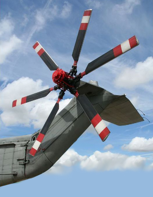
The tail rotor itself is a hazard to ground crews working near a running helicopter. For this reason, tail rotors are painted with stripes of alternating colors to increase their visibility to ground crews while the tail rotor is spinning.

Alternative technologies

[edit]

There have been three major alternative designs which attempt to solve the shortcomings of the tail rotor system.

The first is to use an enclosured ducted fan rather than openly exposed rotor blades. This design is referred to as a fantail or "Fenestron", a trademark of Eurocopter (now Airbus Helicopters) for its Dauphin-series utility helicopters. The enclosure around the fan reduces tip vortex losses, shields the blades from foreign object damage, protects ground crews from potential hazard of an openly spinning rotor, and produces a much quieter and less turbulent noise profile than a conventional tail rotor. The ducted fan uses more numerous shorter blades, but otherwise works in very similar thrust principles to a conventional tail rotor.

MD Helicopters 520N NOTAR

McDonnell Douglas developed the NOTAR (NO TAil Rotor) system, which eliminates having any rotating parts out in the open. The NOTAR system uses a variable pitch ducted fan driven by the helicopter's powerplant, but the ducted fan is mounted inside the fuselage ahead of the tail boom, and the exhaust passes through the tail boom to the end, where it is expelled out one side. This creates a boundary layer which causes the downwash from the main rotor to hug the tail boom according to the Coandă effect. This creates a force which cancels out the main rotor torque and provides directional control. The advantages of the system are similar to the Fenestron system discussed above.

There are at least four ways to eliminate the necessity of a tail rotor altogether :

  • Tandem/transverse rotors: to use two non-overlapping main rotors which rotate in opposite directions, so that the torque created by one rotor cancels out the torque created by the other. Such configurations are commonly seen on heavy-lift helicopters like the tandem-rotored CH-47 Chinook.
The tiltrotor design, as seen on the V-22 Osprey, is a variation of the transverse rotor design, where the rotors are installed in tiltable nacelles at the ends of fixed wings. This allows the rotors to serve instead as propellers when flying forward at full speed.
  • Coaxial. Other designs such as the Kamov Ka-50 and Sikorsky X2 use coaxial counter-rotating main rotors, which means that both rotors spin around the same axis but in opposite directions. The complexity of any dual main rotor system almost invariably requires the addition of a fly-by-wire flight control system, which increases costs drastically.
  • Intermeshing rotors also turn in opposite directions, but the blades rotate into the gaps between the opposing blades so the rotors can intersect each other's path without colliding. Invented by Anton Flettner and used in Flettner Fl 282,[2] Kaman HH-43 Huskie, and Kaman K-MAX.
  • Tip jet. Another way to eliminate the effect of torque created by the rotorwing is by mounting the engine on the tips of the rotorwing rather than inside the helicopter itself; this is called a tip jet. One example of a helicopter using such a system is the NHI H-3 Kolibrie, which had a ramjet on each of the two wingtips, and an auxiliary power unit to spin up the rotor before starting the ramjets. Another example would be the Fairey Rotodyne. Also, unpowered rotors used in autogyro, gyrodyne, and derived concepts do not need a tail rotor either, although nearly all models that utilize this concept of propulsion do need a second propeller in one way or another to drive them forward to begin with.

See also

[edit]

References

[edit]
Revisions and contributorsEdit on WikipediaRead on Wikipedia
from Grokipedia
A tail rotor, also known as an anti-torque rotor, is a smaller, vertically oriented rotor mounted at the tail of a single-main-rotor helicopter, designed primarily to counteract the torque generated by the main rotor system and to provide directional control by adjusting the helicopter's yaw. This component is essential for maintaining stability during hover and low-speed flight, as the main rotor's rotation creates an opposing rotational force on the fuselage that would otherwise cause uncontrolled spinning. In typical designs, the tail rotor consists of two to five blades with adjustable pitch, driven by a tail rotor connected to the main transmission, often via a right-angle gearbox to redirect power along the helicopter's tail boom. Pilots control its thrust by varying blade pitch through pedals, which modulates the sideways force to achieve precise heading changes or to compensate for variations during maneuvers. Design considerations include blade solidity (typically around 0.20 for optimal efficiency), tip speeds of 700–750 feet per second, and positioning to minimize interference from the main rotor wake or , with critical performance evaluated under conditions like 20-knot crosswinds from the right front. Advancements in tail rotor technology have focused on , durability, and performance enhancement; for instance, NASA-developed airfoils like the RC(4)-10 provide zero for smoother operation, while composite materials and swept-tip blades extend service life to 5,000 hours and cut noise by up to 40%. Alternatives to traditional exposed tail rotors include the , a shrouded for improved safety and reduced vulnerability to , and the system, which uses engine exhaust and the Coanda effect for without moving blades, providing up to 60% antitorque in hover. These innovations are particularly vital for applications in , , and high-altitude operations, where reliability under extreme conditions is paramount.

Purpose and Operation

Counteracting Main Rotor Torque

The primary function of the tail rotor in a single main rotor helicopter is to counteract the torque reaction generated by the main rotor system, preventing uncontrolled yaw rotation of the fuselage. According to Newton's third law of motion, which states that every action has an equal and opposite reaction, the main rotor's rotation—typically counterclockwise when viewed from above in conventional designs—produces a clockwise torque on the helicopter body. This torque effect arises as the engine applies force to drive the main rotor against aerodynamic drag, resulting in an equal and opposite rotational tendency on the fuselage. To neutralize this, the tail rotor generates a sideways thrust that produces an opposing torque, maintaining directional stability during hover and low-speed flight. The magnitude of the tail rotor required for balance can be derived from the principle of conservation applied to the helicopter's steady-state operation. The main rotor experiences a QQ (in N·m) from the engine to maintain Ω\Omega against drag; by Newton's third law, this imparts an equal and opposite Q-Q to the . For equilibrium, the tail rotor must generate a counter- equal to QQ. Since the tail rotor TT (in N) acts at a lever arm equal to the tail boom length rr (in m), the balance condition is Q=rTQ = r \cdot T, or rearranged, T=QrT = \frac{Q}{r}. This relationship ensures no net of the body about the vertical axis, as the total external on the sums to zero in steady flight. The derivation follows from the rotational analog of Newton's second law, τ=Iα\tau = I \alpha, where for α=0\alpha = 0 (no ), τ=0\sum \tau = 0, balancing the main rotor reaction with the tail rotor moment. Power consumption by the tail rotor typically accounts for 5-10% of the total engine output in single-rotor helicopters during hover, as it must drive the blades to produce the necessary anti-torque thrust while overcoming its own drag. For example, in the Bell UH-1 Iroquois, a conventional single-engine utility helicopter, the tail rotor draws approximately 10% of engine power in a pure hover to balance the main rotor torque, reducing available power for lift generation. This allocation varies with flight conditions but underscores the efficiency trade-off inherent in tail rotor designs. Variations in altitude and forward speed influence the torque balance by altering air density and airflow over both rotors, requiring dynamic adjustments to tail rotor pitch. At higher altitudes, reduced air density (ρ\rho) decreases the main rotor's lift efficiency, necessitating increased power input and thus higher torque QQ, which demands greater tail rotor thrust; however, the tail rotor's smaller disk area makes it more sensitive to density changes, potentially requiring up to 20% more relative power for equivalent thrust. In forward flight, increasing speed introduces on the main rotor, where the advancing blade generates more lift than the retreating one due to relative wind differences, but this is primarily managed by blade flapping rather than torque; for the tail rotor, forward speed creates its own dissymmetry, unevenly loading blades and inducing a minor rolling moment on the tail boom that indirectly affects yaw stability, though the net anti-torque thrust requirement remains tied to main rotor power. These effects highlight the need for pilot inputs to maintain balance, particularly in high-altitude or high-speed regimes.

Providing Directional Control

The tail rotor enables pilots to control the helicopter's yaw axis by varying the thrust it produces, primarily through anti-torque pedals that adjust the collective pitch of the tail rotor blades. These pedals, positioned on the cabin floor, allow the pilot to increase pitch for greater thrust in one direction—typically right pedal for nose-right yaw (thrust to the left)—or decrease it for the opposite effect, facilitating precise heading changes during hover or low-speed flight. This mechanism generates a horizontal thrust vector that rotates the fuselage about the vertical axis, independent of the main rotor's torque-counteracting baseline function. In , the tail rotor integrates with cyclic and controls to execute coordinated maneuvers, such as turns, where pedal inputs maintain heading while the cyclic tilts the main rotor disc for lateral movement. The yaw response is generally rapid and proportional to pedal deflection, with the time to arrest yaw rates varying based on the magnitude of the input and environmental factors like wind; for instance, full left pedal can halt yaw rates up to 115 degrees per second in certain models like the OH-58A. This responsiveness supports stable pedal turns in hover, achieving 360-degree rotations, and trims the longitudinally during cruise. However, the tail rotor's effectiveness for directional control diminishes in forward flight due to interference from the main rotor's downwash, which reduces the tail rotor's angle of attack and thrust efficiency. Authority limits become evident in high-speed conditions or sidewinds; for example, a 40-knot right crosswind can exceed the tail rotor's capability in helicopters like the Bell 206 or OH-58, necessitating increased left pedal input that may not fully compensate, particularly in wind sectors of 30 to 150 degrees relative. Tailwinds in the 120- to 240-degree sector can accelerate unintended yaw, amplifying the need for proactive pedal adjustments. In , a power-off descent scenario, the tail rotor continues to provide yaw control as it is driven by the main rotor transmission through the freewheeling unit, allowing pedal inputs to adjust pitch and counter transmission drag despite the engine failure. This maintains heading stability throughout the maneuver, with pilots coordinating pedals during the and to prevent yaw excursions, though low rotor rpm in low-inertia systems may require larger inputs for adequate authority.

Design and Components

Blades and Pitch Control

Tail rotor blades are engineered for efficient production at low speeds and in hover conditions, typically consisting of 2 to 5 blades to balance aerodynamic efficiency and structural simplicity. These blades are constructed from lightweight composite materials, such as reinforced plastics, which provide durability and resistance to fatigue; carbon fiber composites were increasingly adopted starting in the to further reduce weight while maintaining high strength-to-weight ratios. profiles, such as the VR-7 or NACA 0012, are selected for their performance in generating lift at low Reynolds numbers and Mach numbers typical of tail rotor operation. The pitch control system enables precise adjustment of blade angle to modulate thrust for directional control, primarily through collective pitch changes rather than cyclic variations. A swashplate assembly, driven by linkages from the pilot's antitorque pedals, tilts or translates to alter the pitch of all blades simultaneously via pushrods and pitch horns; in some designs, individual linear actuators replace the swashplate for direct control. The collective pitch range typically spans 10 to 20 degrees, with maximum angles around 20 degrees critical for high-thrust conditions like hover or maneuvering. Performance of tail rotor blades is influenced by factors such as tip speed and ratio, which determine output and power requirements. Blade tip speeds generally range from 213 to 229 m/s (700 to 750 ft/s), selected to optimize while avoiding excessive effects and . The ratio, defined as the total blade area divided by the rotor disk area, is typically around 0.20 for conventional tail rotors, allowing sufficient with minimal power draw; higher values improve low-speed but increase drag. Tail rotor hubs vary in design between teetering and rigid types to accommodate motions from aerodynamic loads. Teetering hubs, which allow the blade assembly to pivot as a unit, simplify construction and reduce parts compared to rigid hubs with individual flapping hinges; the uses a teetering hub in its two-bladed tail rotor for enhanced simplicity and lower maintenance.

Drive System and Gearbox

The tail rotor drive system transmits power from the main transmission to the tail rotor assembly via a long driveshaft running along the length of the tail boom. This driveshaft typically consists of multiple sections connected by universal joints or flexible couplings to accommodate the bending and torsional loads experienced during flight, ensuring reliable power delivery despite the helicopter's dynamic motions. At the tail boom's end, a gearbox redirects the power 90 degrees to drive the vertical tail rotor shaft, utilizing right-angle for this orientation change. Gear ratios in the tail rotor drive system are designed to optimize performance by increasing the rotational speed from the main rotor output to the tail rotor, typically achieving a speed multiplication of 4:1 to 6:1 relative to the main rotor RPM. For instance, with a main rotor operating at approximately 300 RPM, the tail rotor may reach to RPM, providing sufficient authority while balancing power efficiency. This gearing occurs primarily in the tail rotor gearbox, though the overall reduction from engine speed (often around 3000 RPM) to tail rotor speed incorporates contributions from the main transmission. The drive system is integrated into the tail boom structure for structural efficiency, with the driveshaft supported by hanger bearings at intervals to minimize deflection and . Vibration dampers, such as elastomeric elements in the couplings, further protect components from fatigue caused by operational harmonics. In helicopters with extended tail booms, like the , an intermediate gearbox is incorporated midway along the driveshaft to maintain alignment and distribute loads, connected via interconnecting shafts. Maintenance of the tail rotor drive system emphasizes to reduce wear in high-cycle components like the driveshaft joints and gearboxes, with systems often using dedicated oil reservoirs or grease fittings checked during pre-flight inspections. Wear indicators, such as magnetic chip detectors in the gearboxes, monitor for metallic from gear or bearing degradation, enabling condition-based servicing through health and usage monitoring systems (HUMS). These features are critical given the driveshaft's exposure to continuous rotation and environmental stresses.

Historical Development

Invention and Early Use

In 1912, Russian engineer Boris Nikolaevich Yuryev designed and built one of the world's first helicopters featuring a single main rotor paired with a tail rotor to counteract torque, predating later developments and serving as an early precursor to modern designs. The concept of the tail rotor emerged in the early as engineers grappled with the imbalance produced by a single main rotor in designs, which caused uncontrolled yawing and instability. French engineer Étienne Oehmichen addressed this challenge in his 1920s experiments by incorporating small vertically mounted auxiliary rotors that rotated opposite to the main lifting rotors, providing directional control and stability in his Oehmichen No. 2 quadrocopter, which achieved the first Fédération Aéronautique Internationale (FAI) world record on April 14, 1924. These vertical rotors served as precursors to the modern tail rotor, enabling controlled flight despite the limitations of multi-rotor configurations. German engineer pursued an alternative approach in the mid-1930s, developing the , the first fully controllable practical , which first flew on June 26, 1936. To counter without a tail rotor, Focke employed counter-rotating side-by-side main rotors mounted on outriggers, demonstrating safe landings. This design highlighted the complexities of multi-rotor systems but underscored the need for simpler anti-torque solutions in single-rotor helicopters. Igor Sikorsky advanced the tail rotor to practical maturity with the Vought-Sikorsky VS-300 prototype, the first successful helicopter featuring a single main rotor paired with a dedicated tail rotor for torque compensation and yaw control. The VS-300's initial tethered flight occurred on September 14, 1939, powered by a 75-horsepower engine driving a 28-foot main rotor and a 7.5-foot tail rotor that spun four times faster; its first free flight followed on May 13, 1940. By December 8, 1941, Sikorsky refined the configuration to emphasize main rotor cyclic control, solidifying the single main rotor and tail rotor as the dominant helicopter architecture. The tail rotor's viability was proven in production with Sikorsky's R-4, the world's first mass-produced , which entered service in 1942 following the prototype's debut flight on January 13. Over 100 R-4 units were built for U.S. military evaluation, marking the transition from experimental prototypes to operational . Early alternatives to the tail rotor, such as intermeshing counter-rotating rotors in Charles Kaman's K-225 experimental helicopter—which first flew in 1947—demonstrated superior lift and stability but greater mechanical complexity, ultimately affirming the tail rotor's simplicity and efficiency for most designs.

Evolution in Modern Helicopters

Following , tail rotor technology in helicopters advanced significantly through material innovations that enhanced performance and scalability for larger civil and . In the and , manufacturers shifted from heavier components to aluminum alloys for tail rotor blades and hubs, reducing weight and improving torque counteraction efficiency without compromising structural integrity. This transition supported the development of more versatile designs, such as the JetRanger introduced in 1967, which incorporated an optimized metal tail rotor that contributed to the aircraft's overall and reliability in light utility roles. By the , early adoption of composite materials, including fiberglass-reinforced plastics, began appearing in tail rotor components, enabling lighter constructions that further boosted hover performance and payload capacity in emerging medium-lift helicopters. The 1980s and 1990s saw deeper integration of advanced tail rotor systems in designs, particularly through the , a ducted tail rotor first certified in 1972 but widely refined and incorporated into production models like the AS365 Dauphin during this period. These integrations improved safety and yaw control in confined spaces while reducing vulnerability to . Concurrently, aerodynamic refinements such as swept blade tips emerged to address noise concerns, with designs like those on the demonstrating measurable reductions in tail rotor broadband noise through altered blade-vortex interactions, aiding compliance with evolving urban operation regulations. Into the 2000s, these evolutions extended to larger platforms, where composite tail rotors became standard for weight savings and fatigue resistance, facilitating adaptations for heavy-lift missions. From the onward, tail rotor advancements have focused on and , particularly in unmanned and hybrid-electric systems. Electric actuators have been integrated into tail rotor pitch controls for precise, lightweight operation, reducing hydraulic dependencies and enabling faster response times in dynamic environments. In eVTOL prototypes, companies like advanced certification efforts in 2023, incorporating electric propulsion and control systems that parallel traditional tail rotor functions through vectored thrust for . algorithms, leveraging neural networks and real-time feedback, have also proliferated in unmanned s, optimizing tail rotor authority against varying loads and winds for enhanced . By 2025, composite materials are widely used in civil helicopter tail rotors and contribute significantly to construction, with military models often exceeding 50% composite weight and designs offering up to 40% weight reduction compared to 1980s-era metal ones, as of November 2025.

Reliability and Safety

Common Failure Modes

Tail rotor failures have historically been a significant factor in helicopter accidents, accounting for approximately 5.6% of U.S. civil accidents from 1963 to 1997, with more recent analyses indicating they remain among the leading causes of loss of control events. According to statistics, tail rotor failures rank as the third highest cause of fatal accidents overall. These failures are often non-catastrophic when design redundancies are present, allowing pilots to maintain partial control through or other maneuvers. More recent data as of 2024 shows overall accident rates continuing to decline, with fatal rates at historic lows (0.57 per 100,000 flight hours), though tail rotor issues remain a monitored concern. Mechanical issues frequently arise in tail rotor systems, with driveshaft being a prominent mode due to cyclic loading, pitting, and degradation over time. For instance, in helicopters, tail rotor driveshaft tubes have fractured from cracks originating at sites on the exterior surface, leading to complete loss of thrust. Similarly, in the tail rotor gearbox output shaft have caused sudden power loss, as documented in investigations of incidents. Blade delamination in composite tail rotors, particularly in models like the UH-1, occurs from environmental exposure, paint cracking, and repeated stress, resulting in separation of layered materials and reduced aerodynamic efficiency. Operational causes include external impacts and aerodynamic limitations, such as bird strikes, which often target the exposed tail rotor blades due to low-altitude flight paths. These strikes can sever blades or disrupt pitch control, as seen in multiple Australian Transport Safety Bureau cases where wedgetail eagles caused in-flight breakups. is another critical operational failure, occurring in low-speed, high-power conditions where main rotor or crosswinds reduce tail rotor thrust, leading to unanticipated right yaw in counterclockwise main rotor systems. This phenomenon has been a factor in numerous pilot-error-related accidents involving single-rotor helicopters, per rotorcraft community analyses. Symptoms of tail rotor failures typically manifest as unusual from mechanical wear or imbalance, and uncommanded yaw drift indicating loss, which can be detected through onboard health and usage monitoring systems (HUMS) that track anomalies in real-time. Early detection via monitoring has proven effective in mitigating escalation, as evidenced in Sentient Science prognostic studies on H-60 tail rotor drive systems.

Design and Operational Safeguards

Tail rotor systems incorporate redundancy features to enhance reliability and prevent single-point failures. In designs like the , dual independent hydraulic systems provide redundant control for tail rotor pitch adjustments, ensuring continued operation if one system fails. Additionally, many modern helicopters feature automatic pitch locking mechanisms that secure in the event of power failure to the , maintaining directional control and avoiding uncontrolled yaw. Inspection protocols are critical for maintaining tail rotor integrity under regulatory standards. For operations under FAA Part 135, pre-flight checks require visual examination of the tail rotor assembly, including blades, driveshafts, and control linkages, to detect damage, corrosion, or loose components before each flight. Non-destructive testing (NDT) methods, such as ultrasonics and radioscopy, are mandated for tail rotor blades at intervals like every 100 hours of operation in models such as the , allowing early detection of internal defects without disassembly. Pilot training emphasizes recognition and mitigation of conditions like loss of tail rotor effectiveness (LTE), where main rotor torque overwhelms tail rotor thrust, often during low-speed maneuvers. Standard recovery techniques include applying full opposite pedal (typically left for right yaw in single-engine helicopters), slightly reducing collective to decrease torque, and adding forward cyclic to increase airspeed and translational lift on the tail rotor. These procedures are integrated into FAA-approved training programs, with simulator practice recommended due to the risks of in-flight demonstration. Advancements in the have introduced health and usage monitoring systems (HUMS) for real-time tail rotor anomaly detection. In 2025, Sikorsky partnered with SKYTRAC for real-time HUMS integration on the S-92 helicopter, monitoring tail rotor bearings using sensor data to predict failures, enabling proactive maintenance and improving safety in offshore operations. These systems analyze and temperature metrics during flight, alerting crews to deviations that could precede issues like those seen in past bearing failures.

Alternative Technologies

Ducted Tail Rotors (Fenestron)

The Fenestron is a shrouded variant of the tail rotor, featuring multiple small blades arranged in a configuration at the rear of the helicopter's tail boom. Developed by Sud-Aviation in the , it was first flight-tested on a prototype in 1968 and achieved certification on the production in 1972. Like conventional open tail rotors, the Fenestron generates to counteract the produced by the main rotor and maintain directional control. Subsequent generations evolved the design, including all-composite construction in the late 1970s for a 20% diameter increase to 1.10 meters and uneven blade spacing introduced in 1994 on the H135 to further optimize performance. Key advantages of the Fenestron stem from its enclosed duct, which shields the blades from foreign object debris, ground strikes, and environmental hazards such as sand, rain, snow, and ice, thereby enhancing overall safety for both the and ground personnel. The design also reduces noise emissions compared to open tail rotors, with modern implementations like the H130 achieving external sound levels 6 dB below (ICAO) standards through optimized blade and shroud geometry. Additionally, the ducted structure improves aerodynamic efficiency by directing airflow more effectively, resulting in 2-3% total power savings during forward flight relative to conventional tail rotors. Despite these benefits, the introduces drawbacks, primarily higher weight from the added shroud and components, as well as increased mechanical complexity requiring specialized gearing to achieve the higher rotational speeds typical of ducted fans—often around 10 times the main rotor speed for adequate thrust. Maintenance demands are elevated due to the enclosed assembly, though advancements in composite materials have mitigated some issues in later models. The has become a hallmark of (formerly Eurocopter) designs, finding widespread application in models such as the SA 341 Gazelle, AS365 Dauphin, H130, H135, H145, and the latest H160, where a 1.20-meter version canted at 12 degrees boosts low-speed stability and capacity. For instance, U.S. Coast Guard AS365 Dauphin variants equipped with Fenestrons have accumulated over 1.5 million flight hours, demonstrating proven reliability in demanding maritime operations.

No-Tail-Rotor Systems (NOTAR)

No-Tail-Rotor Systems () represent an innovative approach to counteracting main rotor torque in by eliminating the traditional tail rotor in favor of a pressure-thrust mechanism. The system, developed by McDonnell Douglas Helicopter Systems in the 1980s, relies on engine directed through slots along the tail boom to generate yaw control forces via the Coanda effect, where high-velocity airflow adheres to the boom's surface, creating a lateral that deflects the main rotor wake. This circulation control principle allows the tail boom to function like an , producing anti-torque without mechanical blades or driveshafts. Research into the concept began in 1975, with significant testing in a water tunnel in 1985, leading to the first integrated flight demonstration in 1981 and significant refinements by 1987 through improved fan designs achieving 85% efficiency. Key components of NOTAR include a variable-pitch blower fan mounted within the fuselage, which pressurizes ambient air to approximately 0.5 psi and circulates it through the tail boom, and augmentation nozzles consisting of longitudinal slots (typically two, positioned at angles like 70° and 140° for optimal flow) along the boom's length. A rotating direct jet thruster at the tail end supplements the system by providing precise directional control for the remaining torque, expelling air to generate up to 40% of the total anti-torque force. Thrust is produced through momentum conservation as the thin air stream from the slots interacts with the rotor downwash, avoiding the need for exposed rotating parts and enabling a lightweight composite tail boom structure weighing around 90 pounds. Experimental wind tunnel studies confirm that dual-slot configurations yield higher side force coefficients (up to optimal at momentum coefficients below 0.45) compared to single slots, ensuring stable performance across hover and low-speed conditions. The primary advantages of NOTAR stem from its simplified design, which eliminates maintenance requirements for tail rotor blades, gearboxes, and driveshafts, thereby reducing mechanical complexity and vulnerability to or strikes—common factors in accidents. It also lowers noise levels by up to 50% and , enhancing pilot comfort and operational safety in confined areas, while allowing for increased payload capacity, such as an additional 300 pounds in the MD 520N compared to equivalent tail-rotor models. In hover, NOTAR achieves efficiency comparable to conventional tail rotors, with circulation control providing up to 60% anti-torque through boundary-layer management, though its power draw from the engine limits broader adoption. Applications of NOTAR have been primarily confined to light helicopters due to the system's reliance on for air pressurization. The first production model, the MD 520N, achieved its initial flight on December 29, 1989, and received FAA certification in 1991, entering service for roles including , aerial , , and . Over 750,000 flight hours have been accumulated by the NOTAR fleet, demonstrating reliability in civilian and paramilitary operations, though its implementation remains niche owing to higher power demands in larger aircraft. As of October 2025, upgrades to the MD 530N model integrate a more powerful engine, improving hover performance and payload capacity to support expanded use in demanding environments.

References

Add your contribution
Related Hubs
User Avatar
No comments yet.