
Community hub
Token Ring
View on Wikipedia


Token Ring is a physical and data link layer computer networking technology used to build local area networks. It was introduced by IBM in 1984, and standardized in 1989 as IEEE 802.5. It uses a special three-byte frame called a token that is passed around a logical ring of workstations or servers. This token passing is a channel access method providing fair access for all stations, and eliminating the collisions of contention-based access methods.
Following its introduction, Token Ring technology became widely adopted, particularly in corporate environments, but was gradually eclipsed by newer iterations of Ethernet. The last formalized Token Ring standard that was completed was Gigabit Token Ring (IEEE 802.5z), published on May 4, 2001.[1]
History
[edit]A wide range of different local area network technologies were developed in the early 1970s, of which one, the Cambridge Ring, had demonstrated the potential of a token passing ring topology, and many teams worldwide began working on their own implementations. At the IBM Zurich Research Laboratory Werner Bux and Hans Müller, in particular, worked on the design and development of IBM's Token Ring technology,[2] while early work at MIT[3] led to the Proteon 10 Mbit/s ProNet-10 Token Ring network in 1981[4] – the same year that workstation vendor Apollo Computer introduced their proprietary 12 Mbit/s Apollo Token Ring (ATR) network running over 75-ohm RG-6U coaxial cabling.[citation needed] Proteon later developed an upgraded 16 Mbit/s version that ran on unshielded twisted pair cable.
1985 IBM launch
[edit]IBM launched their own proprietary Token Ring product on October 15, 1985.[5][6] It ran at 4 Mbit/s,[7] and attachment was possible from IBM PCs, midrange computers and mainframes. It used a convenient star-wired physical topology and ran over shielded twisted-pair cabling. Shortly thereafter it became the basis for the IEEE 802.5 standard.[8][failed verification]
During this time, IBM argued that Token Ring LANs were superior to Ethernet, especially under load,[9] but these claims were debated.[10]
In 1988, the faster 16 Mbit/s Token Ring was standardized by the 802.5 working group.[11] An increase to 100 Mbit/s was standardized and marketed during the wane of Token Ring's existence and was never widely used.[12] While a 1000 Mbit/s standard was approved in 2001, no products were ever brought to market and standards activity came to a standstill[13] as Fast Ethernet and Gigabit Ethernet dominated the local area networking market.
Gallery
[edit]-
 100 Mbit/s IBM Token Ring Management Adapter with wake-on-LAN. Both UTP (RJ45) and STP (IBM Data Connector) interfaces are present.
 -
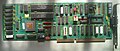
 Assorted full-length Micro Channel Token Ring cards, including a LANStreamer which features multiple RJ45 ports for usage in a Token Ring network
 -
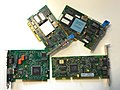 Token Ring Network Interface Cards (NICs) with varying interfaces from: ISA, PCI and Micro Channel
 -
 Madge 4/16 Mbit/s TokenRing ISA NIC
 -
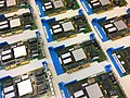 A series of multiple 16/4 early Micro Channel Token Ring cards which would have predominantly been installed in many Personal System/2 machines
 -
 Texas Instruments TMS380C26PQL network communication processor, used in a Hewlett Packard JetDirect Token Ring print server card


Comparison with Ethernet
[edit]Early Ethernet and Token Ring both used a shared transmission medium. They differed in their channel access methods. These differences have become immaterial, as modern Ethernet networks consist of switches and point-to-point links operating in full-duplex mode.
Token Ring and legacy Ethernet have some notable differences:
- Token Ring access is more deterministic, compared to Ethernet's contention-based CSMA/CD.
- Ethernet supports a direct cable connection between two network interface cards by the use of a crossover cable or through auto-sensing if supported. Token Ring does not inherently support this feature and requires additional software and hardware to operate on a direct cable connection setup.[14]
- Token Ring eliminates collision by the use of a single-use token and early token release to alleviate the down time. Legacy Ethernet alleviates collision by carrier-sense multiple access and by the use of an intelligent switch; primitive Ethernet devices like hubs could precipitate collisions due to repeating traffic blindly.[15]
- Token Ring network interface cards contain all of the intelligence required for speed autodetection, routing and can drive themselves on many Multistation Access Units (MAUs) that operate without power (most MAUs operate in this fashion, only requiring a power supply for LEDs). Ethernet network interface cards can theoretically operate on a passive hub to a degree, but not as a large LAN and the issue of collisions is still present.[16]
- Token Ring employs access priority in which certain nodes can have priority over the token. Unswitched Ethernet did not have a provision for an access priority system as all nodes have equal access to the transmission medium.
- Multiple identical MAC addresses are supported on Token Ring (a feature used by S/390 mainframes).[12] Switched Ethernet cannot support duplicate MAC addresses without reprimand.[17]
- Token Ring was more complex than Ethernet, requiring a specialized processor and licensed MAC/LLC firmware for each interface. By contrast, Ethernet included both the (simpler) firmware and the lower licensing cost in the MAC chip. The cost of a token Ring interface using the Texas Instruments TMS380C16 MAC and PHY was approximately three times that of an Ethernet interface using the Intel 82586 MAC and PHY.[citation needed]
- Initially both networks used expensive cable, but once Ethernet was standardized for unshielded twisted pair with 10BASE-T (Cat 3) and 100BASE-TX (Cat 5(e)), it had a distinct advantage and sales of it increased markedly.
- Even more significant when comparing overall system costs was the much-higher cost of router ports and network cards for Token Ring vs Ethernet. The emergence of Ethernet switches may have been the final straw.[citation needed]
Operation
[edit]Stations on a Token Ring LAN are logically organized in a ring topology with data being transmitted sequentially from one ring station to the next with a control token circulating around the ring controlling access. Similar token passing mechanisms are used by ARCNET, token bus, 100VG-AnyLAN (802.12) and FDDI, and they have theoretical advantages over the CSMA/CD of early Ethernet.[18]
Access control
[edit]The data transmission process goes as follows:
- Empty information frames are continuously circulated on the ring.
- When a computer has a message to send, it seizes the token. The computer will then be able to send the frame.
- The frame is then examined by each successive workstation. The workstation that identifies itself to be the destination for the message copies it from the frame and changes the token back to 0.
- When the frame gets back to the originator, it sees that the token has been changed to 0 and that the message has been copied and received. It removes the message from the frame.
- The frame continues to circulate as an empty frame, ready to be taken by a workstation when it has a message to send.
Multistation Access Units and Controlled Access Units
[edit]
Physically, a Token Ring network is wired as a star, with 'MAUs' in the center, 'arms' out to each station, and the loop going out-and-back through each.[19]
A MAU could present in the form of a hub or a switch; since Token Ring had no collisions many MAUs were manufactured as hubs. Although Token Ring runs on LLC, it includes source routing to forward packets beyond the local network. The majority of MAUs are configured in a 'concentration' configuration by default, but later MAUs also supporting a feature to act as splitters and not concentrators exclusively such as on the IBM 8226.[20]

Later IBM would release Controlled Access Units that could support multiple MAU modules known as a Lobe Attachment Module. The CAUs supported features such as Dual-Ring Redundancy for alternate routing in the event of a dead port, modular concentration with LAMs, and multiple interfaces like most later MAUs.[21] This offered a more reliable setup and remote management than with an unmanaged MAU hub.
Cabling and interfaces
[edit]Cabling is generally IBM "Type-1", a heavy two-pair 150 ohm shielded twisted pair cable. This was the basic cable for the "IBM Cabling System", a structured cabling system that IBM hoped would be widely adopted. Unique hermaphroditic connectors, referred to as IBM Data Connectors in formal writing were used. The connectors have the disadvantage of being quite bulky, requiring at least 3 cm × 3 cm (1.2 in × 1.2 in) panel space, and being relatively fragile. The advantages of the connectors being that they are genderless and have superior shielding over standard unshielded 8P8C. Connectors at the computer were usually DE-9 female. Several other types of cable existed such as type 2, and type 3 cable.[22]
In later implementations of Token Ring, Cat 4 cabling was also supported, so 8P8C (RJ45) connectors were used on both of the MAUs, CAUs and NICs; with many of the network cards supporting both 8P8C and DE-9 for backwards compatibility.[19]
-
 IBM Data Connectors on the IBM 8228 Multistation Access Unit
 -
 8P8C 'Media Filters' that plug into an IBM Data Connector converting it for use with 8P8C connectors


Technical details
[edit]Frame types
[edit]Token
[edit]When no station is sending a frame, a special token frame circles the loop. This special token frame is repeated from station to station until arriving at a station that needs to send data.
Tokens are three octets in length and consist of a start delimiter, an access control octet, and an end delimiter.
| Start Delimiter | Access Control | End Delimiter |
|---|---|---|
| 8 bits | 8 bits | 8 bits |
Abort frame
[edit]Used by the sending station to abort transmission.
| SD | ED |
|---|---|
| 8 bits | 8 bits |
Data
[edit]Data frames carry information for upper-layer protocols, while command frames contain control information and have no data for upper-layer protocols. Data and command frames vary in size, depending on the size of the Information field.
| SD | AC | FC | DA | SA | PDU from LLC (IEEE 802.2) | CRC | ED | FS |
|---|---|---|---|---|---|---|---|---|
| 8 bits | 8 bits | 8 bits | 48 bits | 48 bits | Up to 4500 × 8 bits | 32 bits | 8 bits | 8 bits |
- Starting delimiter
- The starting delimiter consists of a special bit pattern denoting the beginning of the frame. The bits from most significant to least significant are J,K,0,J,K,0,0,0. J and K are code violations of Differential Manchester encoding. Differential Manchester encoding has a mid symbol transition for every coded 0 or 1, however the J and K codes do not have a mid symbol transition. Both the Starting Delimiter and Ending Delimiter fields are used to mark frame boundaries.
J K 0 J K 0 0 0 1 bit 1 bit 1 bit 1 bit 1 bit 1 bit 1 bit 1 bit
- Access control
- This byte field consists of the following bits from most significant to least significant bit order: P,P,P,T,M,R,R,R. The P bits are priority bits, T is the token bit which when set specifies that this is a token frame, M is the monitor bit which is set by the Active Monitor (AM) station when it sees this frame, and R bits are reservation bits, which indicate that the next token should be issued with that priority.
+ Bits 0–2 3 4 5–7 0 Priority Token Monitor Reservation
- Frame control
- A one-byte field that contains bits describing the data portion of the frame contents which indicates whether the frame contains data or control information. In control frames, this byte specifies the type of control information.
+ Bits 0–1 Bits 2–7 0 Frame type Control Bits
- Frame type – 01 indicates LLC frame IEEE 802.2 (data) and ignore control bits;
- 00 indicates MAC frame and control bits indicate the type of MAC control frame
- Destination address
- A six-byte field used to specify the destination(s) physical address.
- Source address
- Contains physical address of sending station. It is a six-byte field that is either the local assigned address (LAA) or universally assigned address (UAA) of the sending station adapter.
- Data
- A variable length field of 0 or more bytes, the maximum allowable size depending on ring speed containing MAC management data or upper layer information. Maximum length of 4500 bytes.
- Frame check sequence
- A four-byte field used to store the calculation of a CRC for frame integrity verification by the receiver.
- Ending delimiter
- The counterpart to the starting delimiter, this field marks the end of the frame and consists of the following bits from most significant to least significant: J,K,1,J,K,1,I,E. I is the intermediate frame bit and E is the error bit.
J K 1 J K 1 I E 1 bit 1 bit 1 bit 1 bit 1 bit 1 bit 1 bit 1 bit
- Frame status
- A one-byte field used as a primitive acknowledgment scheme on whether the frame was recognized and copied by its intended receiver.
A C 0 0 A C 0 0 1 bit 1 bit 1 bit 1 bit 1 bit 1 bit 1 bit 1 bit
- A = 1, Address recognized
- C = 1, Frame copied
Active and standby monitors
[edit]Every station in a Token Ring network is either an active monitor (AM) or standby monitor (SM) station. There can be only one active monitor on a ring at a time. The active monitor is chosen through an election or monitor contention process.
The monitor contention process is initiated when the following happens:
- a loss of signal on the ring is detected.
- an active monitor station is not detected by other stations on the ring.
- a particular timer on an end station expires such as the case when a station hasn't seen a token frame in the past 7 seconds.
When any of the above conditions take place and a station decides that a new monitor is needed, it will transmit a claim token frame, announcing that it wants to become the new monitor. If that token returns to the sender, it is OK for it to become the monitor. If some other station tries to become the monitor at the same time then the station with the highest MAC address will win the election process. Every other station becomes a standby monitor. All stations must be capable of becoming an active monitor station if necessary.
The active monitor performs a number of ring administration functions. The first function is to operate as the master clock for the ring in order to provide synchronization of the signal for stations on the wire. Another function of the AM is to insert a 24-bit delay into the ring, to ensure that there is always sufficient buffering in the ring for the token to circulate. A third function for the AM is to ensure that exactly one token circulates whenever there is no frame being transmitted, and to detect a broken ring. Lastly, the AM is responsible for removing circulating frames from the ring.
Token insertion process
[edit]Token Ring stations must go through a 5-phase ring insertion process before being allowed to participate in the ring network. If any of these phases fail, the Token Ring station will not insert into the ring and the Token Ring driver may report an error.
- Phase 0 (Lobe Check) – A station first performs a lobe media check. A station is wrapped at the MSAU and is able to send 2000 test frames down its transmit pair which will loop back to its receive pair. The station checks to ensure it can receive these frames without error.
- Phase 1 (Physical Insertion) – A station then sends a 5-volt signal to the MSAU to open the relay.
- Phase 2 (Address Verification) – A station then transmits MAC frames with its own MAC address in the destination address field of a Token Ring frame. When the frame returns and if the Address Recognized (AR) and Frame Copied (FC) bits in the frame-status are set to 0 (indicating that no other station currently on the ring uses that address), the station must participate in the periodic (every 7 seconds) ring poll process. This is where stations identify themselves on the network as part of the MAC management functions.
- Phase 3 (Participation in ring poll) – A station learns the address of its Nearest Active Upstream Neighbour (NAUN) and makes its address known to its nearest downstream neighbour, leading to the creation of the ring map. Station waits until it receives an AMP or SMP frame with the AR and FC bits set to 0. When it does, the station flips both bits (AR and FC) to 1, if enough resources are available, and queues an SMP frame for transmission. If no such frames are received within 18 seconds, then the station reports a failure to open and de-inserts from the ring. If the station successfully participates in a ring poll, it proceeds into the final phase of insertion, request initialization.
- Phase 4 (Request Initialization) – Finally a station sends out a special request to a parameter server to obtain configuration information. This frame is sent to a special functional address, typically a Token Ring bridge, which may hold timer and ring number information the new station needs to know.
Optional priority scheme
[edit]In some applications there is an advantage to being able to designate one station having a higher priority. Token Ring specifies an optional scheme of this sort, as does the CAN Bus, (widely used in automotive applications) – but Ethernet does not.
In the Token Ring priority MAC, eight priority levels, 0–7, are used. When the station wishing to transmit receives a token or data frame with a priority less than or equal to the station's requested priority, it sets the priority bits to its desired priority. The station does not immediately transmit; the token circulates around the medium until it returns to the station. Upon sending and receiving its own data frame, the station downgrades the token priority back to the original priority.
Here are the following eight access priority and traffic types for devices that support 802.1Q and 802.1p:
| Priority bits | Traffic type |
|---|---|
| x'000' | Normal data traffic |
| x'001' | Not used |
| x'010' | Not used |
| x'011' | Not used |
| x'100' | Normal data traffic (forwarded from other devices) |
| x'101' | Data sent with time sensitivity requirements |
| x'110' | Data with real time sensitivity (i.e. VoIP) |
| x'111' | Station management |
Interconnection with Ethernet
[edit]
Bridging solutions for Token Ring and Ethernet networks included the AT&T StarWAN 10:4 Bridge,[23] the IBM 8209 LAN Bridge[23] and the Microcom LAN Bridge. Alternative connection solutions incorporated a router that could be configured to dynamically filter traffic, protocols and interfaces, such as the IBM 2210-24M Multiprotocol Router, which contained both Ethernet and Token Ring interfaces.[24]
Operating system support
[edit]This section needs expansion. You can help by adding to it. (October 2024) |
In 2012, David S. Miller merged a patch to remove token ring networking support from the Linux kernel.[25]
See also
[edit]- IBM PC Network
- Protocol Wars - The battle between Internet and OSI standards in the 1980s
References
[edit]- ^ "IEEE 802.5 Activities". ieee802.org. IEEE. Retrieved 29 October 2023.
- ^ "IEEE honors Zurich LAN pioneers" (Press release). Zurich, Switzerland: IBM. 14 April 2003.
- ^ J. Noel Chiappa (April–June 2014). "Early Token Ring Work at MIT". IEEE Annals of the History of Computing. 36 (2): 80–85. doi:10.1109/MAHC.2014.14. S2CID 30761524.
- ^ Pelkey, James. "14.18 Proteon in Chapter 14 - Internetworking: Emergence 1985-1988". The History of Computer Communications. Archived from the original on 2023-05-09. Retrieved 2023-05-09.
- ^ "IBM TOKEN-RING NETWORK". IBM. 1985-10-15. Retrieved 2021-03-11.
- ^ Crabb, Don (24 March 1986). "Major Vendors Differ On Network Approach". InfoWorld. Vol. 8, no. 12. p. 27.
- ^ "InfoWorld". 21 November 1988.
- ^ IEEE Standards: P802.5 Working Group Area. Ieee802.org. Retrieved on 2011-10-30.
- ^ IEEE 802.3 Local Area Network considerations. IBM. GG22-9422-0.
- ^ David R. Boggs; Jeffrey C. Mogul; Christopher A. Kent (1988). "Measured capacity of an Ethernet: myths and reality" (PDF). ACM SIGCOMM Computer Communication Review. 25 (1): 123–136. doi:10.1145/205447.205460. S2CID 52820607. Archived from the original (PDF) on 2012-03-02. Retrieved 2007-12-04.
- ^ Urs Von Burg; Martin Kenny (December 2003). "Sponsers, Communities, and Standards: Ethernet vs. Token Ring In The Local Area Networking Business" (PDF). Industry and Innovation. 10 (4). Taylor & Francis Ltd: 351–375. doi:10.1080/1366271032000163621. S2CID 153804163. Archived from the original (PDF) on 2018-02-19.
- ^ a b Jonathan Follows (2000). Token Ring Solutions (PDF) (White paper). IBMInternational Technical Support Organization. Archived from the original (PDF) on 2016-08-06.
IBM does not view high-speed Token Ring as a requirement for the majority of its customers, and therefore the decision has been made not to provide 100 Mbps high-speed Token Ring uplinks on its products...
- ^ "IEEE 802.5 activities". IEEE 802 LAN/MAN Standards Committee. Retrieved 2023-05-09.
- ^ Louis Ohland. "8228 Multistation Access Unit". Ps-2.kev009.com. Archived from the original on 2018-03-28. Retrieved 2016-08-03.
- ^ "What is the difference between an Ethernet hub and switch?". Archived from the original on 14 March 2017. Retrieved 10 May 2016.
- ^ "A Passive Ethernet Hub". Zen22142.zen.co.uk. Archived from the original on 2016-08-24. Retrieved 2016-08-03.
- ^ "networking - Duplicate MAC address on the same LAN possible?". Server Fault. 2013-01-03. Retrieved 2016-08-03.
- ^ Sheesley, John (April 2, 2008). "Does anyone actually still USE Token Ring?". TechRepublic. Archived from the original on 2013-10-09.
- ^ a b "Why buy from IBM?" (PDF). IBM. Archived from the original (PDF) on 2020-06-16. Retrieved 2016-08-03.
- ^ Louis Ohland. "8226 TR RJ45 Connection /Model 001". Ardent Tool of Capitalism. Retrieved 2023-05-09.
- ^ "IBM 8230 Controlled access Unit" (PDF). Public.dhe.ibm.com. Archived from the original (PDF) on 2020-06-16. Retrieved 2016-08-03.
- ^ "Network World". 25 April 1988.
- ^ a b Mier, Edwin (1991-06-03). "Buying Smart". Network World. Vol. 8, no. 21. IDG Network World Inc. p. 56. Retrieved 2016-08-03.
- ^ IBM 2210 Nways Multiprotocol Router Description and Configuration Scenarios - Volume I (PDF) (Third ed.). IBM International Technical Support Organization Raleigh Center. June 1997. SG24-4446-02. Retrieved 2016-08-03.
- ^ Corbet, Jonathan. "The end of the token ring era?". LWN.net. Retrieved 2023-09-22.
General
[edit]- Castelli, Matthew (2002). Network Consultants Handbook. Cisco Press. ISBN 978-1-58705-039-8.
- Gallo, Michael; Hancock, William M. (2001). Networking Explained. Digital Press. ISBN 978-1-55558-252-4.
External links
[edit]Token Ring
View on GrokipediaOverview
Definition and Principles
Token Ring is a local area network (LAN) technology that operates at the physical and data link layers of the OSI model, utilizing a token-passing protocol to control access to the shared communication medium among multiple stations.[4] This approach enables reliable data transmission in a multi-access environment by ensuring that only one station can send data at a time, thereby maintaining orderly network operation.[5] At its core, Token Ring functions through a logical ring structure where a single special frame, known as the token, circulates unidirectionally among the connected stations. The station that possesses the token is granted exclusive rights to transmit data frames onto the network; once transmission is complete or a time limit is reached, the station releases the token for the next station in the sequence.[6] This token-passing mechanism, as defined in the IEEE 802.5 standard, establishes a structured flow of data that regenerates and forwards signals at each station, forming a closed loop for continuous circulation.[4] The token-passing protocol inherently provides deterministic access to the network, guaranteeing each station a finite and predictable waiting time before it can transmit, which eliminates the risk of collisions that can occur in contention-based systems.[5] By restricting transmission to the token holder, the system avoids simultaneous data injections, ensuring conflict-free operation even under high load conditions.[6] Although logically organized as a ring, Token Ring is physically implemented using a star topology, where stations connect to a central wiring concentrator, such as a multistation access unit, to form the ring pathway.[4] This design offers key benefits, including fair access opportunities for all stations regardless of position and predictable performance that supports consistent throughput in environments with multiple active users.[5]Key Characteristics
Token Ring networks operate at standardized data transmission speeds of 4 Mbps in their original implementation and 16 Mbps in the more commonly deployed version, with a later extension supporting 100 Mbps under the IEEE 802.5t amendment.[7][8] These speeds enable reliable local area network connectivity, particularly in environments requiring consistent performance without the variability of contention-based access. A defining feature of Token Ring is its deterministic latency, arising from the token rotation time, which can be approximated as roughly $ N \times \frac{\text{frame size}}{\text{bandwidth}} $, where $ N $ is the number of stations; this calculation reflects the worst-case scenario where each station holds the token to transmit a maximum-sized frame before it reaches a given station.[9] This predictability ensures bounded access delays, making it suitable for applications sensitive to timing variations, unlike probabilistic methods in other networks. Token Ring supports up to 250 stations per ring in IEEE 802.5 configurations, with physical constraints limiting the total ring circumference by propagation delays and station insertion delays to maintain signal integrity within tolerable limits.[10][11] The protocol's high reliability stems from built-in fault tolerance mechanisms, including automatic reconfiguration to isolate and bypass faulty stations or links via beaconing and temporary removal from the ring, as well as procedures to restore connectivity without manual intervention.[12] In high-load scenarios, Token Ring's token-passing media access method achieves near-peak efficiency, often outperforming contention-based systems by avoiding collisions and ensuring fair bandwidth allocation among stations.[7]History
Development and Standardization
The concept of ring topologies for computer networks emerged in the late 1960s and early 1970s through academic research aimed at efficient local data communication. In 1969, John Newhall and colleagues proposed an early ring network design, initially known as the Newhall ring, which connected stations in a closed loop for sequential data transmission, laying foundational ideas for token-based access in shared media environments.[13] At MIT, researchers in the 1970s explored variations, including star-shaped ring configurations to enhance maintainability while preserving logical ring signaling, addressing challenges like fault isolation in pure ring setups.[14] Concurrently, the Cambridge Ring project at the University of Cambridge began in 1974, developing a slotted ring architecture for high-speed local area networking at 10 Mbit/s, which demonstrated practical implementation of distributed control and influenced subsequent commercial designs.[15] IBM's development of Token Ring technology commenced in 1977 at its Zurich Research Laboratory, drawing inspiration from these academic efforts, including consultations with MIT's Jerry Saltzer and the Cambridge Ring's slotted approach.[16] By fall 1980, IBM formed an internal task force led by engineers Daniel Warmenhoven and Murray Bolt to create a proprietary local area network, selecting token passing over alternatives like Ethernet to ensure deterministic performance and compatibility with IBM's ecosystem.[16] Prototypes were operational by 1981, incorporating key innovations such as a logical ring overlaid on a physical star topology—using a central multistation access unit (MAU) for wiring concentration and fault tolerance—and dual monitors (active and standby) to maintain ring stability by detecting and resolving issues like lost tokens without disrupting the network.[17] These features prioritized reliability for enterprise environments, with the physical star enabling easier cabling and isolation of failures compared to pure rings.[18] The standardization process began in 1982 when IBM submitted its Token Ring proposal to the IEEE 802 committee, integrating it as the token ring access method alongside other LAN proposals like token bus (802.4) and CSMA/CD (802.3).[19] After iterative working group reviews and balloting, IEEE 802.5 was ratified in 1985, defining the medium access control (MAC) and physical layer specifications for 4 Mbit/s operation over shielded twisted-pair cabling, with provisions for peer-to-peer communication and source routing.[20] The standard emphasized backward compatibility and extensibility, establishing Token Ring as a viable alternative to Ethernet for controlled-access networks. Subsequent evolution of IEEE 802.5 included amendments to support advanced media and speeds. In 1997, IEEE 802.5j introduced fiber optic station attachments, enabling longer distances (up to 2 km) and higher bandwidth for dedicated Token Ring links while maintaining compatibility with the base standard.[21] By 2000, IEEE 802.5t extended the protocol to 100 Mbit/s over unshielded twisted pair and fiber, incorporating dedicated full-duplex modes and enhanced error handling to meet growing enterprise demands without altering core token passing mechanics.[22] These updates reflected ongoing refinements to adapt Token Ring for diverse physical environments and performance needs.Launch, Adoption, and Decline
IBM officially launched its Token Ring network on October 15, 1985, following an initial announcement of development efforts in 1984, with the product featuring 4 Mbps adapters compatible with IBM PCs and midrange systems.[23][24] The technology quickly gained traction in enterprise settings, particularly those reliant on IBM mainframes, where its deterministic access and reliability suited mission-critical applications during the late 1980s and 1990s.[7][25] Adoption peaked in this period, driven by IBM's ecosystem dominance and support from third-party vendors such as Ungermann-Bass, which provided compatible components for broader integration. By 1990, Token Ring held a substantial market share in local area networks, capturing over 57% of the 4 Mbps adapter segment and significant portions of enterprise deployments worldwide.[26][27] Its use extended to large organizations valuing predictable performance over Ethernet's contention-based approach, though growth was somewhat limited by IBM's proprietary influences on the ecosystem.[28] The decline of Token Ring began in the mid-1990s as Ethernet evolved with lower costs, simpler twisted-pair cabling, and higher speeds, exemplified by the introduction of Fast Ethernet at 100 Mbps in 1995, which outpaced Token Ring's then-common speeds of up to 16 Mbps. Token Ring's higher hardware complexity, installation challenges, and overall expense further eroded its competitiveness against Ethernet's scalability and vendor openness.[1][29][30] IBM ceased active development of Token Ring around 1998, shifting focus to Ethernet-compatible solutions. The IEEE 802.5 working group, responsible for Token Ring standardization, was disbanded in 2008 following the withdrawal of the standard in 2008, though some legacy networks continue to operate in niche industrial and mainframe environments.[3][31][32]Architecture
Network Topology
Token Ring networks employ a logical ring topology, where stations are logically arranged in a closed loop to facilitate unidirectional circulation of a control token, ensuring orderly access to the shared medium.[7] In this configuration, data flows sequentially from one station to the next around the ring, with each station receiving and relaying frames until they return to the originating station.[1] Physically, Token Ring implements a star topology, with all stations connected to a central multistation access unit (MAU) that internally wires the connections to form the logical ring.[33] This design uses twisted-pair cabling from each station (known as a lobe) to the MAU, which provides the illusion of a ring without direct station-to-station wiring, enhancing manageability and isolation of faults.[3] Key ring parameters include a maximum of 250 stations for 16 Mbps operation using shielded twisted-pair cabling, balancing performance and reliability.[34] Each lobe segment is limited to approximately 100 meters in passive MAU configurations at 16 Mbps to minimize signal attenuation and maintain timing integrity.[34] For fault tolerance, IEEE 802.5c introduces dual ring capability, allowing a counter-rotating backup path that can automatically reconfigure upon primary ring failure, supporting high-availability applications by wrapping around damaged segments.[35] In terms of ring closure, the logical loop is formed by connecting the head-end output of the first station to the tail-end input of the last station via the MAU's internal bypassing mechanism; inactive stations are optically or electronically bypassed, ensuring continuous circulation without interruption.[33]Components and Interfaces
The Multistation Access Unit (MAU) serves as the central wiring concentrator in Token Ring networks, enabling multiple stations to connect in a star topology while logically forming a ring. It features ports for station attachments via lobe cables and includes ring-in (RI) and ring-out (RO) ports to daisy-chain multiple units, supporting up to 260 devices with shielded twisted pair cabling or 72 devices with unshielded twisted pair. The IBM 8228 MAU, for example, provides 8 ports for stations plus RI/RO ports, operates at 4 Mbps or 16 Mbps, and uses internal relays to insert or bypass stations without active power management.[25][8] The Controlled Access Unit (CAU) extends the MAU's functionality with active management capabilities, acting as a powered concentrator that monitors and controls access to the ring. It includes features like soft error reporting, automatic station bypass for faults, and integration with network management protocols such as SNMP. The IBM 8230 CAU supports up to 92 ports through lobe attachment modules (LAMs) and lobe insertion units (LIUs), with dual ring redundancy via primary and secondary ports, and can handle lobe lengths over 100 meters at 4 Mbps or 16 Mbps.[25][8] Network Interface Cards (NICs), also known as Token Ring adapters, provide the physical and data link layer connectivity for end stations to the network. These cards, such as IBM's 16/4 Token Ring PCI Adapter, include a unique 48-bit IEEE-assigned address in ROM for identification and support auto-sensing of ring speeds (4 Mbps or 16 Mbps). They handle frame processing and token management, often featuring AUI-like ports for media attachment and compatibility with various cabling types.[25][8] Token Ring networks primarily use shielded twisted pair (STP) cabling, such as IBM Type 1 (two pairs, 150-ohm impedance, supporting up to 350 meters at 4 Mbps), Type 2 (six pairs for combined voice/data), Type 6 (jumper cables up to 100 meters), and Type 9 (plenum-rated). Unshielded twisted pair (UTP) options include Type 3 (four pairs, Category 3 or 5, limited to 72 stations per segment due to interference susceptibility). Fiber optic cabling, like Type 5 (two 100/140-micron fibers), enables high-speed backbones up to 2 km, offering immunity to electromagnetic interference.[25][36] Interfaces in Token Ring adhere to the IEEE 802.5 physical layer specifications, which define signaling and connectivity for 4 Mbps and 16 Mbps operations using differential Manchester encoding. Common connectors include RJ-45 for UTP lobe cables (e.g., on CAU LAMs) and DB-9 (IEEE "ugly plug") for STP attachments. Lobe cables, serving as short point-to-point links from NICs to MAUs or CAUs, typically measure up to 100 meters and use hermaphroditic IBM data connectors for STP, ensuring reliable ring insertion.[25][8][2]Operation
Token Passing Mechanism
In Token Ring networks, the token serves as a special three-byte control frame that circulates continuously around the logical ring, granting transmission rights to the station that possesses it.[36] This frame consists of a starting delimiter byte, an access control byte, and an ending delimiter byte, ensuring synchronization and indicating the token's availability for use. The token is passed sequentially from one station to the next in a unidirectional manner, forming the core of the medium access control protocol defined in IEEE 802.5.[2] When a station receives the token, it examines its own queue to determine if data transmission is required.[37] If no data is pending, the station simply regenerates and forwards the token to its downstream neighbor without modification, allowing the token to continue circulating promptly.[1] However, if the station has data to send, it seizes the token by altering the access control byte and converts it into a data frame by appending the necessary header, payload, and trailer information.[36] The station then transmits this frame onto the ring, where it circulates until it returns to the originating station, which verifies successful delivery (via acknowledgment bits set by the destination) and removes the frame before regenerating and releasing a new free token.[37] To prevent any single station from monopolizing the network, the token holding time (THT) limits the duration a station can retain and use the token, typically set to 10 milliseconds for 4 Mbps rings or scaled proportionally for higher speeds like 16 Mbps. During this interval, the station may transmit multiple frames if available, but upon THT expiration, it must release the token regardless of remaining data.[2] This mechanism ensures fair access and bounded latency for all stations on the ring.[38] In the event of token loss—due to corruption, frame errors, or other transient faults—stations detect the absence through a configured timeout period, after which the network reinitializes the token circulation process to restore operation.[38] This basic recovery approach maintains network availability without requiring complex reconfiguration in most cases.[1]Access Control and Monitors
In Token Ring networks, access to the medium is regulated through the access control (AC) field within frames, which is a single-byte field containing specific bits for managing transmission rights and ring operations. This field includes a 1-bit token field that distinguishes tokens from data or command frames (set to 0 for tokens and 1 for frames), a 1-bit monitor field used by the active monitor to track frame circulation and prevent indefinite looping, a 3-bit priority field that indicates the frame's priority level, and a 3-bit reservation field allowing stations to reserve the token for future use based on their priority needs.[3][39] The active monitor (AM) is a designated station responsible for maintaining ring stability and coordinating key operations, including generating free tokens, timing token rotations to enforce the ring's latency limits, and purging any frames that circulate endlessly by stripping their trailing delimiters. The AM is elected through the claim token process, in which stations detect the absence of an active monitor (such as after a timeout or ring initialization) and transmit special claim token frames containing their MAC address; the station with the highest MAC address wins the contention after up to seven rounds of circulation, assuming the role and notifying others via an active monitor present frame.[11][40] Standby monitors (SMs) serve as backups to the AM, with all non-AM stations configured in this role; they periodically transmit standby monitor present frames to report their status and monitor for AM failure, such as by detecting missing active monitor present frames or excessive token rotation times, at which point any SM can initiate a new claim token process to assume the AM role.[11] Neighbor notification enhances fault isolation by enabling each station to identify and communicate with its nearest active upstream neighbor (NAUN), the station immediately preceding it in the ring; during ring insertion or maintenance, stations exchange neighbor information frames to confirm connectivity and report any anomalies, allowing localized diagnostics without disrupting the entire network.[11] Ring maintenance relies on beaconing and autoreconfiguration to handle faults like cable breaks or station failures. When a station detects a signal loss or duplicate address, it transmits beacon frames repeatedly; stations within the failure domain (the beaconing station, its NAUN, and the segment between them) then perform autoreconfiguration by activating internal relays in the multistation access unit (MAU) or using latch mechanisms to electrically bypass the faulty component, restoring ring operation without manual intervention. After approximately 26 seconds without resolution, the initiating station performs auto-removal by temporarily removing itself from the ring to test if it is the fault source.[11][41]Frame Formats
Token and Control Frames
In Token Ring networks, token and control frames serve essential roles in managing access to the shared medium and maintaining ring integrity without carrying user data. The token frame acts as a permission signal that circulates continuously around the logical ring, allowing a station to seize it for transmission when it arrives. Control frames, including the abort frame and various MAC (Media Access Control) control frames, facilitate error recovery, network diagnostics, and coordination among stations. These frames are defined in the IEEE 802.5 standard and implemented in hardware to ensure deterministic access and fault tolerance.[2] The token frame is a compact 3-byte structure designed for rapid circulation. It consists of a starting delimiter (SD), an access control (AC) byte, and an ending delimiter (ED). The SD is a 1-byte field encoded with J-K symbols (specifically J:K:0:J:K:0:0:0 in differential Manchester encoding) to signal the beginning of the frame and violate the standard bit encoding for unambiguous detection. The AC byte includes 3 priority bits (P), 3 reservation bits (R), a token bit (T set to 0 to indicate a token rather than a data frame), and a monitor bit (M set to 0). The ED is another 1-byte field (J:K:1:J:K:1:0:0) that marks the end and includes an intermediate frame indicator (I) and error bit (E), both set to 0 for tokens. This minimal format ensures low overhead, enabling the token to traverse the ring at speeds of 4 or 16 Mbps without impeding performance.[42] The abort frame, also 3 bytes long, is used by a station to prematurely terminate a transmission, such as when an error occurs or a frame exceeds the token holding time. It mirrors the token frame's structure: an SD (J:K:0:J:K:0:0:0), an AC byte (with T=1 to distinguish it from a token, and other bits configured for abort signaling), and an ED (J:K:1:J:K:1:1:0, where I=1 indicates an abort). Stations detect and remove the abort frame to clear the ring, preventing indefinite circulation of damaged frames.[42] MAC control frames are specialized non-data frames that support ring management functions, following a structure similar to data frames but with a frame control (FC) byte indicating control type (e.g., FC=40h for MAC frames) and a variable information field for parameters. Key examples include the Duplicate Address Test (DAT) frame, which a station transmits upon joining the ring to check for address conflicts; it includes the source address in the information field and uses counters to track responses, with no replies expected if the address is unique. The Active Monitor Present (AMP) frame, sent periodically by the active monitor every 7 seconds, broadcasts the monitor's address and its nearest active upstream neighbor (NAUN) to synchronize stations and initiate neighbor notification processes. Neighbor notification frames, triggered by AMP, allow stations to update their NAUN by copying addresses from passing frames and responding if needed, ensuring each station knows its immediate predecessor for diagnostics. Other control frames, such as beacon and ring purge, handle fault isolation and token regeneration but follow analogous formats. These frames typically include SD, AC (with M=0 for initial circulation), FC, destination/source addresses (often broadcast), a 1- to 6-byte information field, a 4-byte frame check sequence (FCS) for CRC-32 error detection, and ED.[42] At the physical layer, Token Ring employs differential Manchester encoding for data bits, but delimiters use special J and K symbols to create code violations that reliably frame boundaries amid potential noise. The J symbol lacks a transition at the bit cell start, while K lacks it at the midpoint, forming non-standard 5-bit patterns (e.g., J=00 or 11, K=01 or 10 in NRZ representation) that stations detect as violations to synchronize without ambiguity. Code violations outside delimiters signal errors, incrementing station counters for line errors and triggering recovery.[42] Control frames circulate the ring like tokens, with stations examining the AC and FC fields to determine actions: they may copy information, set status bits, or strip the frame if designated (e.g., the active monitor purges duplicates). The monitor bit prevents endless looping by flipping after one rotation, prompting removal and token reinsertion. This process integrates with the overall token passing to maintain orderly ring operation.[42]| Frame Type | Length (bytes) | Key Fields | Primary Purpose |
|---|---|---|---|
| Token | 3 | SD (1), AC (1), ED (1) | Circulate access permission |
| Abort | 3 | SD (1), AC (1), ED (1) | Halt faulty transmission |
| MAC Control (e.g., AMP, DAT) | Variable (min. 21) | SD (1), AC (1), FC (1), Addresses (12), Info (var.), FCS (4), ED (1), FS (1) | Ring diagnostics and coordination |