
Community hub
Recent from talks
Contribute something
Nothing was collected or created yet.
Constructive solid geometry
View on Wikipedia
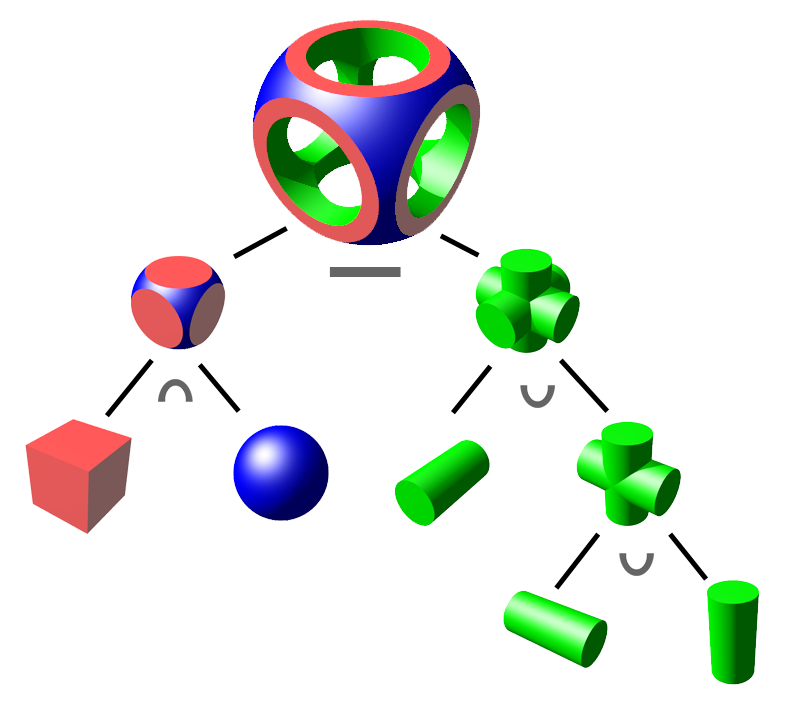
Constructive solid geometry (CSG; formerly called computational binary solid geometry) is a technique used in solid modeling. Constructive solid geometry allows a modeler to create a complex surface or object by using Boolean operators to combine simpler objects,[1] potentially generating visually complex objects by combining a few primitive ones.[2][3]
In 3D computer graphics and CAD, CSG is often used in procedural modeling. CSG can also be performed on polygonal meshes, and may or may not be procedural and/or parametric.
CSG can be contrasted with polygon mesh modeling, boundary representation, and box modeling.
Workings
[edit]The simplest solid objects used for the representation are called geometric primitives. Typically they are the objects of simple shape: cuboids, cylinders, prisms, pyramids, spheres, cones.[1] The set of allowable primitives is limited by each software package. Some software packages allow CSG on curved objects while other packages do not.
An object is constructed from primitives by means of allowable operations, which are typically Boolean operations on sets: union (OR), intersection (AND) and difference (NOT), as well as geometric transformations of those sets.[1]
A primitive can typically be described by a procedure which accepts some number of parameters; for example, a sphere may be described by the coordinates of its center point, along with a radius value. These primitives can be combined into compound objects using operations like these:
-
 Union
Union
Merger of two objects into one -
 Difference
Subtraction of one object from another -
 Intersection
Portion common to both objects


Combining these elementary operations, it is possible to build up objects with high complexity starting from simple ones.
Ray tracing
[edit]Rendering of constructive solid geometry is particularly simple when ray tracing. Ray tracers intersect a ray with both primitives that are being operated on, apply the operator to the intersection intervals along the 1D ray, and then take the point closest to the camera along the ray as being the result.
Applications
[edit]
Constructive solid geometry has a number of practical uses. It is used in cases where simple geometric objects are desired,[citation needed] or where mathematical accuracy is important.[4] Nearly all engineering CAD packages use CSG (where it may be useful for representing tool cuts, and features where parts must fit together).
The Quake engine and Unreal Engine both use this system, as does Hammer (the native Source engine level editor), and Torque Game Engine/Torque Game Engine Advanced. CSG is popular because a modeler can use a set of relatively simple objects to create very complicated geometry.[3] When CSG is procedural or parametric, the user can revise their complex geometry by changing the position of objects or by changing the Boolean operation used to combine those objects.
One of the advantages of CSG is that it can easily assure that objects are "solid" or water-tight if all of the primitive shapes are water-tight.[5] This can be important for some manufacturing or engineering computation applications. By comparison, when creating geometry based upon boundary representations, additional topological data is required, or consistency checks must be performed to assure that the given boundary description specifies a valid solid object.[1]
A convenient property of CSG shapes is that it is easy to classify arbitrary points as being either inside or outside the shape created by CSG. The point is simply classified against all the underlying primitives and the resulting boolean expression is evaluated.[6] This is a desirable quality for some applications such as ray tracing.[6]
Conversion from meshes to CSG
[edit]With CSG models being parameterized by construction, they are often favorable over usual meshes when it comes to applications where the goal is to fabricate customized models. For such applications it can be interesting to convert already existing meshes to CSG trees. This problem of automatically converting meshes to CSG trees is called inverse CSG.
A resulting CSG tree is required to occupy the same volume in 3D space as the input mesh while having a minimal number of nodes. Simple solutions are preferred to ensure that the resulting model is easy to edit. Solving this problem is a challenge because of the large search space that has to be explored. It combines continuous parameters such as dimension and size of the primitive shapes, and discrete parameters such as the Boolean operators used to build the final CSG tree.
Deductive methods solve this problem by building a set of half-spaces that describe the interior of the geometry. These half-spaces are used to describe primitives that can be combined to get the final model.[7]
Another approach decouples the detection of primitive shapes and the computation of the CSG tree that defines the final model. This approach exploits the ability of modern program synthesis tools to find a CSG tree with minimal complexity.[8]
There are also approaches that use genetic algorithms to iteratively optimize an initial shape towards the shape of the desired mesh.[9]
Notable applications with CSG support
[edit]Generic modelling languages and software
[edit]Ray tracing and particle transport
[edit]Computer-aided design
[edit]- AutoCAD
- Autodesk Inventor
- Autodesk Fusion 360
- BRL-CAD
- CATIA
- FreeCAD
- NX CAD
- SolveSpace
- Onshape
- OpenSCAD
- PTC Creo Parametric (formerly known as Pro/Engineer)
- Realsoft 3D
- Rhino
- Solid Edge
- SolidWorks
- Tinkercad
- Vectorworks
Gaming
[edit]- Dreams
- Godot[10]
- GtkRadiant
- LittleBigPlanet
- Roblox
- Unity, via free or paid plug-ins from the Unity Asset Store.
- UnrealEd
- Valve Hammer Editor
Others
[edit]References
[edit]- ^ a b c d Foley, James D. (1996), "12.7 Constructive Solid Geometry", Computer Graphics: Principles and Practice, Addison-Wesley Professional, pp. 557–558, ISBN 9780201848403,
- ^ Roth, Scott (1982). "Ray Casting for Modeling Solids". Computer Graphics and Image Processing. 18 (2): 109–144. doi:10.1016/0146-664X(82)90169-1.
- ^ a b Bloomenthal, Jules; Bajaj, Chandrajit (1997), "5.2.5 Intersection with CSG Trees", Introduction to Implicit Surfaces, Morgan Kaufmann, pp. 178–180, ISBN 9781558602335.
- ^ Foley (1996), p. 559.
- ^ van Rossen, Sander; Baranowski, Matthew (2011), "Real-time constructive solid geometry", in Ansari, Marwan (ed.), Game Development Tools, CRC Press, pp. 79–96, ISBN 9781439867723.
- ^ a b Glassner, Andrew S. (1989), An Introduction to Ray Tracing, Morgan Kaufmann, p. 80, ISBN 9780122861604.
- ^ Buchele, Suzanne F.; Crawford, Richard H. (2004). "Three-dimensional halfspace constructive solid geometry tree construction from implicit boundary representations". Computer-Aided Design. 36 (11): 1063–1073. doi:10.1016/j.cad.2004.01.006.
- ^ Du, Tao; Inala, Jeevana Priya; Pu, Yewen; Spielberg, Andrew; Schulz, Adriana; Rus, Daniela; Solar-Lezama, Armando; Matusik, Wojciech (2018). "InverseCSG: automatic conversion of 3D models to CSG trees". ACM Trans. Graph. doi:10.1145/3272127.3275006.
- ^ Fayolle, Pierre-Alain; Pasko, Alexander A. (2016). "An evolutionary approach to the extraction of object construction trees from 3D point clouds" (PDF). Computer-Aided Design. 74: 1–17. doi:10.1016/j.cad.2016.01.001.
- ^ Godot Engine - Godot gets CSG support
- ^ Gregory, Paul (February 12, 2002). "Major release". Retrieved May 20, 2020 – via SourceForge.
- ^ Magica CSG website
- ^ Womp website
Constructive solid geometry
View on GrokipediaIntroduction
Definition and Principles
Constructive solid geometry (CSG) is a technique for defining complex three-dimensional solids by combining simple geometric primitives through Boolean operations—such as union, intersection, and difference—and applying rigid transformations, including translation, rotation, and scaling. This approach enables the construction of intricate models in a hierarchical manner, where primitives serve as building blocks and operations define their spatial relationships.[9] In CSG, solids are represented implicitly as subsets of Euclidean three-space (), focusing on the volume enclosed by the solid rather than an explicit description of its boundary surfaces.[9] A core principle is the point classification scheme, which determines for any point in space whether it lies inside the solid, outside it, or on its boundary; this classification ensures precise, unambiguous representations that avoid gaps, overlaps, or inconsistencies in the model.[9] Primitives in CSG are parametric geometric objects, such as a sphere specified by its center coordinates and radius . Mathematically, CSG solids are treated as regular sets in Euclidean space, forming a Boolean algebra closed under regularized operations: union (), intersection (), and difference ().[9]History
The origins of constructive solid geometry (CSG) trace back to the 1960s and 1970s, when early efforts in solid modeling emerged as part of advancements in computer-aided design (CAD). Ivan Sutherland's Sketchpad system, developed in 1963 as part of his PhD thesis at MIT, introduced interactive computer graphics and influenced subsequent boundary representation (B-rep) techniques, laying groundwork for volumetric modeling approaches that CSG would later build upon. By the 1970s, researchers at the University of Rochester's Production Automation Project (PAP) began exploring set-theoretic methods for representing solid objects, drawing from computational geometry and set theory to enable precise, unambiguous descriptions of three-dimensional shapes.[10] A key milestone came in 1977 with the formalization of CSG in a technical memorandum by Aristides A. G. Requicha, which defined CSG as a scheme for composing solids using Boolean operations on primitive volumes, implemented within the PAP's BUILD modeling environment.[10] This was further elaborated in Requicha and Herbert B. Voelcker's 1982 paper, which provided a historical assessment of solid modeling systems, including the BUILD group of modelers, and established CSG as a standard for exact representation in engineering applications.[3] In the 1980s, CSG gained adoption in CAD systems such as PADL-1 (1979) and PADL-2 (1980), both developed at Rochester, which used CSG for defining and displaying solid objects via a specialized language.[11] These systems also facilitated integration with B-rep methods in hybrid approaches, enhancing flexibility for manufacturing and analysis tasks. During the 1990s, CSG expanded into computer graphics, particularly through ray tracing techniques that efficiently handled Boolean operations on implicit solids for rendering complex scenes in films and games.[12] Pixar's RenderMan software, introduced in 1988 and widely used by the 1990s, incorporated CSG support for modeling and shading, contributing to productions like Toy Story (1995).[12] In the 2000s and 2010s, CSG saw a revival in open-source tools and game engines; for instance, Godot added native CSG support in 2018 to aid level prototyping through primitive combinations.[13] Ongoing research from the 2020s has explored AI-assisted CSG generation, using machine learning to automate the creation of procedural models from sketches or specifications, building on foundational set-theoretic principles.[14]Fundamentals
Primitive Solids
In constructive solid geometry (CSG), primitive solids serve as the fundamental building blocks from which more complex models are assembled. These primitives are typically simple, parameterized geometric objects that can be precisely defined and manipulated to represent basic shapes in three-dimensional space.[15][16] Common primitive types include cuboids, cylinders, spheres, cones, and tori, each defined by a set of geometric parameters that specify their position, size, and orientation. A cuboid is typically parameterized by minimum and maximum coordinates along each axis, forming a rectangular box aligned with the coordinate system. Cylinders are defined by an axis direction, radius, and height, allowing representation of circular prisms. Spheres require only a center point and radius, providing isotropic shapes. Cones are specified by an apex point, base radius, and height, while tori use major and minor radii to define their ring-like structure. These primitives enable the modeling of a wide range of mechanical and architectural forms through their inherent symmetry and simplicity.[15][16] Infinite primitives, such as half-spaces and planes, extend the capabilities of CSG by allowing unbounded regions in models. A half-space is defined by a bounding plane, with all points on one side of the plane considered interior; this is useful for clipping or defining infinite extents in assemblies. Infinite cylinders or wedges can also serve as primitives, providing directional unbounded volumes that facilitate the construction of open or semi-infinite structures.[15][16] Each primitive is mathematically parameterized as a classification function , where is a point in space, and the function evaluates whether is inside, outside, or on the boundary of the solid. For example, for a sphere centered at with radius , the condition is for points inside or on the boundary. This implicit representation supports efficient point classification, essential for subsequent geometric evaluations.[5][15] In CSG, primitives act as the leaf nodes in a hierarchical construction tree, forming the base level from which complex solids are built through combinations. This structure allows for modular design, where primitives can be instanced and transformed to create intricate assemblies without redundant definitions.[15][16] Advanced CSG systems incorporate extensions such as swept primitives, which generate solids by extruding two-dimensional profiles along paths, and user-defined primitives tailored to specific applications. Swept primitives, for instance, include translational extrusions of polygons or rotational sweeps around an axis, enhancing the expressiveness for manufacturing-oriented models. User-defined primitives allow integration of custom shapes, often derived from parametric curves or surfaces, in specialized software environments.[15][16]Boolean Operations
In constructive solid geometry (CSG), Boolean operations provide the foundational mechanisms for combining solid primitives to form complex models, drawing directly from set theory applied to the volumes occupied by these primitives.[9] The three primary operations—union, intersection, and difference—enable the construction of new solids by manipulating the point sets that define the interiors of the operands, ensuring the resulting models maintain well-defined boundaries and volumes.[9] The union operation, denoted , combines two solids and to include all points belonging to either solid, effectively merging their volumes while preserving any overlapping regions without alteration.[9] Geometrically, this operation increases the overall volume and can simplify topologies by connecting separate components into a single cohesive shape, such as fusing two adjacent spheres into an hourglass-like form.[17] In contrast, the intersection operation, , retains only the points common to both solids, yielding the overlapping volume and potentially reducing complexity by extracting shared regions, for example, carving a lens-shaped solid from two intersecting cylinders.[9] The difference operation, , includes points in that are not in , subtracting the volume of from to create cutouts or concavities, such as hollowing a tunnel through a block.[9] These operations alter the topology of the resulting solid: union expands connectivity and volume, intersection isolates overlaps to form bounded intersections, and difference introduces voids or indentations that can increase surface genus.[1] Union and intersection exhibit both commutativity ( and ) and associativity ( and ), allowing the order and grouping of operands to be rearranged without changing the outcome.[18] Difference, however, is neither commutative () nor associative (), requiring careful specification of operand order in constructions.[9] Due to the associativity of union and intersection, these operations extend naturally to n-ary forms in CSG representations, where multiple primitives can be combined in a single expression within hierarchical trees, facilitating scalable model building.[18]Representation and Computation
CSG Trees and Data Structures
Constructive solid geometry (CSG) models are typically represented as ordered binary trees, where leaf nodes contain primitive solids and internal nodes specify regularized Boolean operations such as union, intersection, or difference, enabling a recursive hierarchical construction of complex objects from simpler components.[15] This tree structure ensures that the model defines unambiguous regular sets (r-sets), particularly when using bounded primitives, by applying operators to subtrees in a well-defined order.[15] Each node in the CSG tree stores the operator type for internal nodes—along with pointers to child subtrees—or the geometric parameters defining the primitive for leaf nodes, often including transformation matrices to account for rigid body motions like translations or rotations applied to subtrees.[15] These transformations allow for instancing and positioning of primitives without duplicating data, maintaining compactness in the representation.[19] To evaluate a CSG tree, such as for point classification, a depth-first traversal is employed, starting from the root and recursively propagating the inside/outside status of a point through the subtrees by applying the Boolean operators at each internal node until reaching the leaves, where primitive membership tests determine the initial status.[15] For efficient computation, CSG trees are often augmented with bounding volume hierarchies (BVHs), where each node maintains a bounding volume enclosing the solid represented by its subtree, enabling quick rejection of queries (e.g., ray intersections) that miss these volumes and accelerating traversal in complex models.[20] These BVHs are constructed recursively, with parent volumes derived from the union of child volumes transformed appropriately, providing tight enclosures especially in cyclic variants.[20] Serialization of CSG models for interchange between systems is supported by formats implemented in libraries like OpenCSG, which represent trees as vectors of primitives with associated operation flags and transformation data, facilitating rendering and export without full evaluation.[21] A variant of the binary tree representation is the directed acyclic graph (DAG), which generalizes trees by allowing multiple parents for nodes to share subtrees, thereby reducing redundancy and memory usage in models with repeated primitives or structures, such as those generated procedurally.[19] This sharing preserves the hierarchical evaluation while enabling more compact storage for intricate designs.[17]Point Classification Algorithms
Point classification in constructive solid geometry (CSG) determines whether a given point lies inside, outside, or on the boundary of a solid defined by a CSG tree. This operation is fundamental for tasks such as rendering, collision detection, and solid evaluation, as it enables point-wise assessment without computing the full boundary representation. The standard approach involves recursively traversing the CSG tree, classifying the point against primitive solids at leaf nodes, and propagating results upward using Boolean operator rules. The recursive classification algorithm begins at the root of the CSG tree and evaluates the point's status by descending through nodes. For primitive solids, classification relies on geometric tests specific to the primitive type. For example, in a sphere primitive with center and radius , the point is inside if , outside if , and on the boundary if . Similar tests apply to other primitives like cylinders or boxes, often using distance metrics or halfspace inequalities. At Boolean operator nodes, the classifications from child subtrees are combined according to the operator, following regularized set theory: for union, the point is inside if inside at least one child (including on the boundary of one and inside the other), outside if outside both, and on the boundary if on the boundary of exactly one and outside the other (on both boundaries is typically on the boundary); for intersection, inside if inside both, outside if outside at least one, and on the boundary if on the boundary of one and inside the other (or on both); for difference (A \ B), inside if inside A and outside B (or on boundary A and outside B), outside otherwise, with on boundary A and on boundary B typically outside, and on boundary B and inside A typically inside (adjusted for regularization). These rules ensure compliance with regularized set theory to handle topological consistency. Pseudocode for the algorithm can be expressed as follows, returning an enumeration {inside, outside, boundary}:function classify(node, point):
if node is primitive:
return classify_primitive(node, point) // e.g., sphere distance test
elif node is boolean_operator:
left_status = classify(node.left, point)
right_status = classify(node.right, point)
return combine(left_status, right_status, node.operator)
// Handle transformations if present by applying inverse to point
function classify(node, point):
    if node is primitive:
        return classify_primitive(node, point)  // e.g., sphere distance test
    elif node is boolean_operator:
        left_status = classify(node.left, point)
        right_status = classify(node.right, point)
        return combine(left_status, right_status, node.operator)
    // Handle transformations if present by applying inverse to point
combine function implements operator-specific logic, such as logical OR for union interiors. This post-order traversal ensures all subtrees are evaluated before combining results.
Numerical stability is critical due to floating-point precision errors, particularly near boundaries. An epsilon tolerance, often called a "fuzz factor," is introduced in primitive tests: a point is considered inside if the distance metric is less than , outside if greater than , and on the boundary otherwise. This prevents misclassification from round-off errors, with typically set to a small fraction of the primitive's scale, such as . For boundary cases involving multiple overlapping surfaces (e.g., "on/on" ambiguities), neighborhood information—such as surface normals—may be computed to resolve status by perturbing the point slightly or using topological rules.
To optimize traversal, bounding volumes like axis-aligned bounding boxes (AABBs) are associated with each node, computed conservatively from child bounds. Before recursing into a subtree, the point is checked against the node's AABB: if outside, the subtree can be skipped (early termination), as the point cannot be inside that sub-solid. This reduces evaluations in sparse trees, especially for deep hierarchies, though worst-case performance remains unchanged.
The time complexity of point classification is , where is the number of nodes in the CSG tree, as each node is visited at most once in the traversal, with constant-time operations per node assuming fixed primitive complexity. This efficiency holds independent of the overall model complexity for individual point queries, making it suitable for repeated evaluations in applications like ray tracing.
Rendering and Implementation
Ray Tracing Techniques
In ray tracing for constructive solid geometry (CSG), rays are cast from the viewpoint through each pixel to determine visibility and shading by computing intersections with the solid's boundary defined by the CSG tree. The process begins by parameterizing the ray as , where is the origin, is the direction, and is the parameter. For each primitive solid in the CSG tree (such as spheres, cylinders, or cones), the ray-primitive intersections are solved analytically to find entry and exit points, yielding intervals along the ray where it penetrates the solid. This approach was pioneered by Roth in 1982, who introduced ray casting as a method to model and render CSG solids by treating rays as probes that intersect primitive surfaces.[22] Boolean operations are applied recursively to these intervals as the ray traverses the CSG tree from leaves to root. For a union, the resulting interval is the union of overlapping or adjacent child intervals; for an intersection, it is the overlap of child intervals; and for a difference, the second child's interval is subtracted from the first. The final set of intervals represents the segments of the ray inside the composite solid, enabling accurate determination of entry and exit points for the entire object. Interval arithmetic enhances robustness by bounding potential intersection ranges and avoiding numerical issues in root-finding for higher-degree polynomials from combined primitives. This interval-based technique for CSG rendering was further refined by Duff in 1982 using recursive subdivision and interval evaluation for implicit surfaces.[23] To find the surface hit for shading, the closest intersection is selected as the minimal from the final intervals, with point classification determining whether it is a front-facing (entry) or back-facing (exit) surface based on the ray direction and surface normal. Acceleration structures are essential for efficiency, particularly for complex trees; bounding volume hierarchies (BVHs) enclose subtrees with simple volumes (e.g., spheres or boxes), allowing rays to prune non-intersecting branches early via cheap ray-bounding volume tests before descending into primitives. Hybrid methods combine tree traversal with spatial partitioning, such as k-d trees, to further reduce computations in large scenes. These techniques, building on early space subdivision heuristics, enable practical rendering of CSG models.[24] CSG ray tracing emerged in the 1980s as a method for rendering non-polygonal scenes, providing exact intersections for high-fidelity effects like shadows and reflections without tessellation, as demonstrated in Roth's foundational work on ray casting for solid modeling.[22]Boolean Operation Algorithms
Boolean operation algorithms in constructive solid geometry (CSG) compute the explicit boundary representation of the resulting solid from applying union, intersection, or difference operations to two or more primitives, enabling conversion from the implicit CSG tree to a tangible surface model.[25] These algorithms typically begin with constructive evaluation, where the solids are decomposed into their boundary polygons—such as the faces of polyhedral primitives—and intersections are computed by clipping these polygons against the supporting planes of the opposing solid. For instance, the Sutherland-Hodgman clipping algorithm, originally for 2D polygons, is adapted to 3D by successively clipping polyhedral faces against each plane equation of the other solid's boundaries, generating intersection curves that form the new edges of the result. This process ensures that only portions of the boundaries contributing to the final solid are retained, with clipping rules determining whether vertices lie inside, outside, or on the plane to build the clipped polygon. In the 1980s, seminal implementations like the PADL-2 solid modeling system developed boundary evaluation techniques that classify the edges and vertices of one solid's boundary relative to the other solid using set membership tests against its half-spaces. This classification identifies active boundary elements—those that survive the Boolean operation—and computes their intersections via plane-plane or edge-plane intersections, followed by reconstruction of the resulting boundary through neighborhood manipulations that connect valid faces, edges, and vertices while discarding invalid portions. The algorithm processes the CSG tree recursively, evaluating subtrees to merge boundaries at each operation node, ensuring topological consistency in the output.[25] Modern methods advance these foundations by leveraging arrangements of surfaces, where the input boundaries are partitioned into cells defined by all intersecting planes or surfaces, followed by topological merging to select cells belonging to the resulting solid based on the Boolean operator. Libraries such as CGAL implement these using Nef polyhedra, a data structure that represents polyhedral solids closed under Boolean operations with robust exact arithmetic to avoid floating-point errors in intersection computations and handle degenerate cases like coplanar faces.[26] The output is typically a boundary representation (B-rep) consisting of oriented faces, edges, and vertices, which may include non-manifold features such as shared edges between multiple faces when the operation produces complex topologies.[27] The computational complexity of these algorithms is O(n²) in the worst case for n primitives, dominated by pairwise intersection tests between boundary elements, though optimizations like spatial hashing—via bounding volume hierarchies or voxel grids—reduce practical runtime by accelerating proximity queries and clipping operations.Advantages and Limitations
Key Benefits
Constructive solid geometry (CSG) provides exact representations of solid objects by combining primitive solids through Boolean operations, ensuring watertight models without gaps, overlaps, or tessellation-induced errors that plague polygonal approximations. This precision arises from the mathematical foundation of regularized set operations, which define unambiguous interiors, boundaries, and exteriors for the resulting solids, making CSG particularly suitable for applications requiring tight manufacturing tolerances, such as CNC machining. Unlike boundary representations that may accumulate floating-point errors in edge intersections, CSG maintains fidelity to the original primitives throughout the modeling process.[9] CSG enables compact storage of complex geometries via hierarchical trees composed of a limited number of primitives and operations, significantly reducing data requirements compared to explicit mesh representations. This efficiency scales well for parametric models, as modifications to primitive parameters update the entire structure without regenerating vast vertex lists, facilitating storage and transmission in resource-constrained environments.[9] The topological robustness of CSG stems from its reliance on point classification algorithms to determine inside/outside status relative to primitives and subtrees, preventing cracks or inconsistencies in renders and simulations that often arise in mesh-based models due to numerical instability. By syntactically guaranteeing the validity of solids constructed from bounded primitives, CSG avoids invalid topologies like self-intersections or non-manifold edges, enabling reliable computations for volume, mass properties, and interference detection. This inherent structure supports automated design verification without extensive error-checking routines.[9] Parametric flexibility in CSG allows changes to primitive dimensions or positions to propagate automatically through the Boolean tree, streamlining iterative design processes and supporting generative modeling where families of related objects are derived from adjustable parameters. For example, scaling a primitive in a CSG representation instantly recomputes the entire model's geometry via set operations, preserving exactness without manual adjustments to dependent features—a capability less intuitive in dense mesh formats that require remeshing. This adaptability enhances collaboration in engineering workflows, where design variations can be explored efficiently.[9]Challenges and Drawbacks
One major challenge in constructive solid geometry (CSG) is its high computational cost, stemming from the need to evaluate the CSG tree for each point or ray during rendering or intersection tests. In a balanced tree with n primitives, naive evaluation can reach O(n^2) time complexity due to repeated traversals and classifications across subtrees, rendering it inefficient for dense ray tracing or models with large n without specialized acceleration like bounding volume hierarchies.[28] This overhead is exacerbated in voxel-based or octree implementations, where Boolean operations process objects element by element, significantly increasing demands on hardware resources.[29] Editing CSG models presents further difficulties, as deep hierarchical trees obscure the underlying geometry and make modifications non-intuitive. The binary tree structure, with unevaluated Boolean operations, lacks direct access to individual surfaces or features, requiring users to navigate complex decompositions that may not reflect the original design intent, thus complicating iterative adjustments.[30] Additionally, CSG representations are often hard for humans to interpret without converting to boundary representations, limiting practical usability in design workflows.[31] Rendering CSG models imposes significant limitations, particularly for real-time applications, where computing exact intersections with the implicit tree is prohibitively expensive compared to rasterizing polygonal meshes. Interactive modifications further amplify this issue, as re-evaluating the tree for dynamic scenes strains graphics hardware, often necessitating approximations like polygonization to achieve viable frame rates.[32] Numerical instability also arises from floating-point errors in boundary classification and intersection computations, which can produce leaks, spurious artifacts, or inconsistent results due to round-off inaccuracies in geometric predicates.[33] Scalability issues limit CSG to relatively simple models, as explicit evaluation of deep trees can lead to exponential growth in computational demands with increasing hierarchy depth, making it impractical for highly complex assemblies without simplification or pruning techniques.[34] This constraint is particularly evident in hardware-constrained environments, where direct CSG implementation becomes unfeasible for large-scale scenes.[35] Recent advances, such as machine learning approaches for generating CSG trees (as of 2024), are helping to address editing and scalability challenges by automating complex model construction.[36]Applications
Computer-Aided Design
Constructive solid geometry (CSG) plays a pivotal role in parametric modeling within computer-aided design (CAD) systems, enabling engineers to construct complex parts through feature-based operations on primitive solids. In software like SolidWorks, CSG serves as a foundational planning tool for determining the sequence and number of features required, such as extrusions, revolves, and Boolean combinations, to build models incrementally.[37] Similarly, AutoCAD supports CSG techniques for solid modeling, allowing users to create features like subtracting cylindrical holes from rectangular blocks to form components with precise cutouts.[38] This approach facilitates parametric adjustments, where dimensions of primitives can be varied to regenerate the entire model while maintaining design intent. In manufacturing applications, CSG's exact representation of volumes supports the generation of precise toolpaths for CNC machining by enabling accurate intersection calculations between tools and solids.[39] CSG models allow for simulation of material removal processes, ensuring collision-free paths and optimal cutting strategies without approximations that could lead to errors in production. Furthermore, CSG integrates seamlessly with tolerance specifications in CAD, incorporating dimensional constraints on primitives and supporting interference detection through Boolean evaluations to verify assembly fits.[40][41] A notable case study in aerospace involves modeling lightweight structural components as unions and differences of primitive solids like cylinders and swept surfaces to optimize weight while preserving strength.[42] This method allows rapid iteration for generative design, ensuring manufacturable geometries that meet stringent performance criteria. Today, modern building information modeling (BIM) tools incorporate CSG for creating architectural solids, such as combining extruded walls and subtracted openings from point cloud data to reconstruct as-built environments efficiently.[43]Computer Graphics and Gaming
In computer graphics, constructive solid geometry (CSG) has been instrumental in rendering complex scenes for films through ray tracing techniques, particularly in early CGI productions. Pixar's RenderMan, introduced in the 1980s, supports CSG to assemble primitive shapes like spheres and cylinders into organic forms, enabling efficient ray-object intersections for high-fidelity visuals in animations such as those in the movie Cars (2006), where ray tracing extensions handled intricate lighting and shadows.[44][45] This approach allowed artists to model detailed environments by combining and subtracting primitives without exhaustive manual meshing, prioritizing conceptual forms over polygon counts.[12] CSG found early prominence in game engines for level design, exemplified by id Software's Quake (1996), which employed CSG operations on "brushes"—basic polyhedral primitives—to subtract volumes and carve architectural spaces like corridors and rooms from solid blocks.[46] This subtractive workflow streamlined the creation of interconnected indoor environments, with the engine's binary space partitioning (BSP) tree compiling CSG results into efficient renderable geometry for real-time play.[47] Quake's editor tools facilitated rapid iteration, influencing subsequent FPS titles by balancing procedural flexibility with performance constraints of 1990s hardware.[48] Contemporary game engines like Unreal and Unity integrate CSG as a hybrid with polygonal meshes to support procedural generation, converting CSG trees into optimized meshes for runtime efficiency. In Unreal Engine, CSG brushes enable boolean operations during level authoring, which are then baked into static meshes for dynamic worlds, as seen in procedural cave systems or urban layouts generated via the Procedural Content Generation (PCG) framework.[49][50] Unity's runtime CSG plugins, such as those performing unions and intersections on primitives, hybridize with mesh combiners to produce deformable structures, allowing in-game modifications like destructible terrain without full voxel overhead.[51][52] These approximations address real-time rendering challenges by limiting CSG depth and precomputing intersections where possible.[53] Beyond static geometry, CSG defines complex collision volumes in physics engines for particle simulations, where boolean combinations of primitives create accurate bounding shapes for environmental interactions. In engines like Unity's PhysX integration, CSG-generated meshes serve as compound colliders, enabling particles—such as debris or fluids—to respond realistically to subtracted voids or unioned obstacles during simulations of explosions or erosion effects.[54] This method ensures precise detection without over-simplifying shapes, though it requires mesh export for optimal performance in high-particle counts.[53] Notable implementations highlight CSG's role in rapid prototyping and modding. Godot Engine introduced CSG nodes in version 3.1 (2018), allowing developers to combine primitives via unions, intersections, and subtractions for quick level mockups, which can be exported as meshes for final integration.[13] In voxel-based games, Minecraft mods like mcthings leverage procedural CSG on grid-aligned blocks to sculpt terrain or structures, treating voxels as discrete primitives for boolean operations in custom worlds.[55] These tools emphasize CSG's accessibility for interactive graphics, fostering experimentation in both professional and community-driven projects.[56]Conversions and Extensions
Meshes to CSG
Converting polygonal meshes to constructive solid geometry (CSG) representations enables the transformation of explicit surface models into implicit, editable tree structures composed of primitives and Boolean operations. This process is particularly useful for simplifying complex geometries obtained from scanning or modeling, allowing subsequent modifications through parametric adjustments. Techniques for this conversion typically involve intermediate representations or optimization to approximate the mesh with a hierarchy of solids, balancing fidelity and compactness.[57] One common approach is voxelization, where the mesh is rasterized into a volumetric grid to identify occupied regions, followed by fitting geometric primitives to clusters of voxels via optimization algorithms. The mesh is first reconstructed into a watertight surface if necessary, then voxelized by casting rays or using space partitioning to classify grid cells as inside or outside the solid. Primitives such as boxes, cylinders, or spheres are then fitted to dense voxel clusters using least-squares optimization or region-growing methods, with the resulting set assembled into a CSG tree through greedy union and subtraction to minimize deviation from the original volume. This method excels for organic shapes but can introduce stair-step artifacts in fine details due to grid resolution limits.[57][58] Another technique extracts half-spaces from the mesh's facets to reconstruct the CSG tree, leveraging planar approximations of the boundary. Supporting planes are identified from mesh triangles by clustering coplanar facets and computing their equations, distinguishing natural half-spaces (directly bounding the solid) from separating ones (internal to the decomposition). These half-spaces form primitive solids, which are combined via Boolean operations to match the mesh topology, often using algorithms that enumerate fundamental products or optimize the tree for minimality. This approach is efficient for polyhedral meshes with flat faces but struggles with curved surfaces, requiring segmentation into quasi-planar patches.[57][59] In the 2020s, AI-driven methods have advanced mesh-to-CSG conversion, employing program synthesis, genetic algorithms, and neural networks to generate compact trees. Program synthesis frames the problem as searching for a CSG expression that satisfies point-membership queries sampled from the mesh, using satisfiability solvers like Sketch to explore primitive combinations and operations. Genetic algorithms evolve CSG trees by mutating primitives and operators, evaluating fitness against mesh samples via volume overlap metrics, with enhancements like deterministic filtering of input points improving convergence on noisy data. Neural approaches, such as those using diffusion models or graph neural networks, parse meshes into primitive detections and tree structures, achieving unsupervised learning of hierarchical decompositions with reduced tree depth. For instance, hybrid genetic methods on meshes can yield more compact trees while preserving high volumetric accuracy, often outperforming manual approximations in efficiency. These techniques prioritize minimizing tree complexity for editability. More recent advancements as of 2024 include diffusion models that generate CSG trees directly from meshes, enhancing automation for complex mechanical designs.[60][57][61][14] Tools like OpenSCAD support mesh import via STL files, allowing users to approximate imported geometries with CSG primitives through manual hulling or Minkowski sums, though automatic conversion remains limited and often requires external preprocessing. Challenges persist in faithfully representing curved surfaces, as CSG primitives (e.g., spheres or cylinders) may necessitate deep trees or approximations that may introduce errors in curvature fidelity.[62] Such conversions find applications in reverse engineering scanned objects, where 3D scans of physical parts are processed into editable CSG models for design iteration or manufacturing. For example, voxelized scans of mechanical components can be decomposed into primitives matching original CAD intent, facilitating parametric modifications in tools like OpenSCAD. This enables rapid prototyping from legacy artifacts, with reported success in reconstructing assemblies from point clouds.[60][57]CSG to Boundary Representations
Converting a Constructive Solid Geometry (CSG) model to a boundary representation (B-rep) involves evaluating the implicit solid defined by the CSG tree to produce an explicit description of its surface, typically as a polygonal mesh or faceted model. This process, known as boundary evaluation, is essential for applications requiring direct access to surface geometry, such as rendering or simulation, where CSG's hierarchical structure is inefficient. The conversion generates a manifold or non-manifold boundary consisting of vertices, edges, and faces that enclose the solid volume without redundancy. Boundary evaluation begins by traversing the CSG tree to identify all surface fragments derived from the boundaries of primitive solids, such as spheres, cylinders, or polyhedra. For each primitive, an initial polygonal approximation of its surface is created. Interfering portions—where primitives overlap due to Boolean operations—are subdivided iteratively to capture intersection curves accurately. These fragments are then clipped against the half-spaces defined by neighboring primitives in the tree, retaining only those portions that lie on the exterior or interior boundaries of the final solid as determined by the Boolean operators (union, intersection, difference). This clipping ensures that only valid surface elements contribute to the output, eliminating internal or extraneous parts. The process handles complex topologies by propagating classifications (inside/outside) through the tree, often using ray casting or point inclusion tests at subdivision points.[63] Following boundary evaluation, polygonization assembles the clipped surface fragments into a coherent manifold mesh. This involves classifying edges based on their role in the boundary—such as boundary edges (free edges) or internal edges (shared by adjacent faces)—using direction flags to indicate orientation relative to the solid's interior. Vertex snapping aligns vertices from adjacent fragments to intersection curves or shared points, preventing gaps or overlaps by projecting them to the nearest valid position on the primitive boundaries. Adjoining coplanar polygons are merged by removing common edges, resulting in a non-redundant mesh with consistent topology. For non-manifold features, like edges shared by more than two faces, additional classification resolves ambiguities to maintain watertightness.[63][64] Several algorithms facilitate this conversion, balancing accuracy and efficiency. The marching method adapts techniques like marching cubes to CSG by classifying grid points within the solid's bounding volume as inside or outside via tree traversal, then generating triangles only in cells intersected by the boundary. Propagation-based variants traverse active cells efficiently, using Euler operators (e.g., make vertex-surface-face or make edge-vertex) to build oriented triangles incrementally, ensuring topological validity even for non-manifold cases like holes. Alternatively, direct B-rep construction computes the arrangement of primitive surfaces, where half-space clipping and intersection curves form a precise faceted representation without voxelization, suitable for exact polyhedral outputs. These methods handle non-convex results by enforcing proper face winding (e.g., counterclockwise for outward normals) to define oriented surfaces correctly. Common output formats include STL, which tessellates the B-rep into triangles for 3D printing, preserving volume enclosure despite approximations.[65][66] Such conversions enable key use cases, including preparation for finite element analysis (FEA), where the explicit B-rep provides boundary elements for meshing and load application, and GPU-accelerated rendering, where tessellated meshes leverage hardware rasterization more effectively than ray-traced CSG evaluation.[67][68]Notable Implementations
Software and Libraries
Commercial computer-aided design (CAD) software such as SolidWorks employs constructive solid geometry (CSG) principles within its feature-based modeling workflow, where primitives and Boolean operations form the foundation for constructing complex parts.[69] Similarly, AutoCAD supports CSG-like solid modeling through its 3D solids tools, enabling union, subtraction, and intersection operations on basic shapes for engineering design.[70] Open-source libraries provide robust implementations for CSG tasks. OpenCSG is a C++ library specialized in image-based CSG rendering using OpenGL, allowing efficient visualization of Boolean combinations without explicit mesh generation.[71] The Computational Geometry Algorithms Library (CGAL) offers exact Boolean operations on Nef polyhedra in C++, supporting robust 3D CSG computations for applications requiring precision, such as computational geometry research.[26] Script-based modeling tools leverage CSG for programmatic design. OpenSCAD is an open-source software that uses a scripting language to define 3D models via CSG primitives and operations, ideal for parametric and reproducible designs in 3D printing.[72] Blender, a popular open-source 3D creation suite, supports CSG through its native Boolean modifier, which performs union, intersection, and difference operations on meshes. Add-ons like SD5 extend this with signed distance field-based modeling using libfive.[73][74] Programming interfaces extend CSG accessibility in development environments. CadQuery, a Python library built on Open CASCADE Technology, enables parametric CSG operations including union, difference, and intersection, facilitating script-driven CAD model creation.[75] FreeCAD's Part module, part of its open-source parametric modeler, supports CSG through the Open CASCADE kernel, allowing Boolean operations on solids in a Python-scriptable workbench.[76] A notable recent open-source library is Manifold, a C++ geometry library providing fast and robust CSG operations on manifold triangle meshes, ensuring topological correctness. It serves as a backend for tools like OpenSCAD and Godot Engine, supporting applications in 3D printing and real-time graphics as of 2025.[77] For interoperability in manufacturing, the ISO 10303 (STEP) standard facilitates CSG data exchange by defining constructs for geometric and topological representations, including CSG trees and primitives in application protocols like AP203 and AP214.[78]Specific Tools and Examples
In game engines, the id Tech engine, powering the Quake series, employed constructive solid geometry (CSG) operations during level compilation to build binary space partitioning (BSP) trees from brush-based designs, enabling efficient rendering of complex indoor environments.[79] Similarly, Godot Engine version 3.1 and later introduced CSG nodes that support union, intersection, and subtraction operations on 2D and 3D primitives, facilitating rapid prototyping of levels and assets directly in the editor.[80] For ray tracing applications, POV-Ray utilizes CSG to combine primitive shapes—such as spheres, boxes, and cylinders—through union, intersection, difference, and merge operations, allowing offline rendering of intricate solid scenes without explicit surface meshing.[81] NVIDIA's OptiX ray tracing engine accelerates CSG evaluations by constructing GPU-optimized acceleration structures for binary tree-based solids, achieving interactive rendering speeds for massive models in simulations.[82] In particle transport simulations, the Monte Carlo N-Particle (MCNP) code from Los Alamos National Laboratory relies on CSG representations to define complex geometries, including combinatorial assemblies of primitives for neutron and photon tracking in nuclear applications.[83] This approach supports layered CSG models that integrate with Monte Carlo methods for accurate transport calculations in reactor designs.[84] Niche applications include medical imaging, where CSG techniques model organs such as the heart and lungs by combining primitive volumes to approximate anatomical structures from MRI or CT data, aiding in phantom development for radiation dosimetry.[85] In robotics, CSG volumes enable precise collision detection by evaluating set operations on solid hierarchies, identifying intersections between manipulator paths and environmental obstacles in real-time motion planning.[86] A recent example is Unity's ProBuilder tool, integrated since version 2019.1, which provides in-editor CSG brushing via its experimental Boolean operations to subtract, union, or intersect meshes, streamlining procedural level design for game development.[87]References
- https://en.wikibooks.org/wiki/OpenSCAD_User_Manual/STL_Import_and_Export