Hubbry Logo
Friction torqueFriction torqueMain
Open search
Friction torque
Community hub
Friction torque
logo
8 pages, 0 posts
0 subscribers
Be the first to start a discussion here.
Friction torque
Friction torque
from Wikipedia
This image displays an example situation where there is an active frictional torque. The large black vector arrow represents the primary force acting on the bar (the thick black line), causing it to rotate around the gray dot at its opposite end which represents an axle. The large red vector arrow represents the torque caused by the primary force. The small black vector arrow represents the frictional force caused by the bar sliding across the second bar (grey).

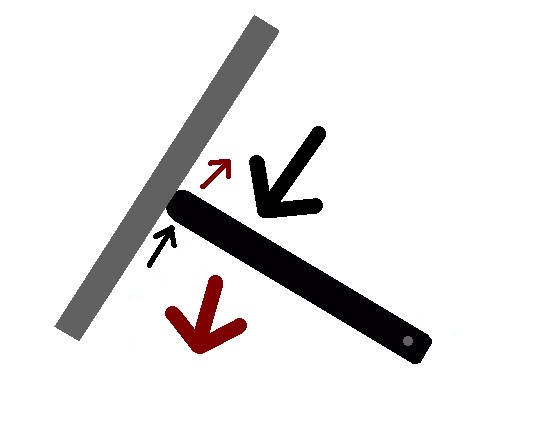
In mechanics, friction torque is the torque caused by the frictional force working in couple that occurs when two objects in contact move.[1] Like all torques, it is a rotational force that may be measured in newton meters or pounds-feet.

Engineering

[edit]

Friction torque can be disruptive in engineering. There are a variety of measures engineers may choose to take to eliminate these disruptions. Ball bearings are an example of an attempt to minimize the friction torque.[2]

Friction torque can also be an asset in engineering. Bolts and nuts, or screws are often designed to be fastened with a given amount of torque, where the friction is adequate during use or operation for the bolt, nut, or screw to remain safely fastened. This is true with such applications as lug nuts retaining wheels to vehicles, or equipment subjected to vibration with sufficiently well-attached bolts, nuts, or screws to prevent the vibration from shaking them loose.[3]

Examples

[edit]
  • When a cyclist applies the brake to the forward wheel, the bicycle tips forward due to the frictional torque between the wheel and the ground.[4]
  • When a golf ball hits the ground it begins to spin in part because of the friction torque applied to the golf ball from the friction between the golf ball and the ground.[5]

References

[edit]

See also

[edit]
Revisions and contributorsEdit on WikipediaRead on Wikipedia
from Grokipedia
Friction torque is the resistive torque produced by frictional forces acting between surfaces in contact during rotational motion, opposing the applied torque and converting mechanical energy into heat. It manifests in mechanical systems such as bearings, , shafts, and , where it influences , power loss, and operational performance. In rotating machinery, friction torque arises from multiple mechanisms, including Coulomb friction (constant magnitude opposing motion, independent of speed), viscous friction (proportional to angular velocity, common in fluid-lubricated systems), and combined effects like rolling and sliding in bearings. For viscous friction, the torque τ\tau is modeled as τ=Brω\tau = B_r \omega, where BrB_r is the rotational friction coefficient (in N·m·s/rad) and ω\omega is the angular velocity. In rolling bearings, friction torque is notably low, with coefficients of friction typically ranging from 0.001 to 0.005, making it about 1/100th that of sliding bearings; it is calculated as M=μPdM = \mu P d, where μ\mu is the friction coefficient, PP is the equivalent load, and dd is the bore diameter in mm. Key factors influencing its magnitude include load, speed, lubrication type (e.g., grease or oil), temperature, and internal clearance or preload, with higher values at startup due to boundary lubrication where asperities contact directly. The significance of friction torque lies in its impact on system efficiency and heat generation; for instance, power loss QQ from in bearings is given by Q=0.105×10⁶MnQ = 0.105 \times 10^{-6} M n (in kW, with MM the friction torque in N·mm and nn in rpm), which can limit speed and lifespan if unmanaged. Proper and bearing selection minimize it, transitioning from high-friction boundary regimes to low-friction full-film , thereby enhancing durability in applications like electric motors, turbines, and automotive components.

Fundamentals

Definition

Torque, the rotational equivalent of linear force, measures the effectiveness of a force in causing an object to rotate about an axis, calculated conceptually as the force multiplied by its perpendicular distance from the axis. Friction torque is the specific type of torque generated by frictional forces that oppose rotational motion in mechanical systems, such as between contacting surfaces in bearings, , or shafts. It arises when frictional resistance at the contact interface produces a moment arm effect, conceptually expressed as the product of the friction force and the radial distance from the rotation axis to the point of contact. The formalization of friction torque concepts emerged in the late through studies of frictional resistance in mechanical systems. , a French and , conducted pioneering experiments on dry in 1781, establishing laws that describe as proportional to the normal force and independent of contact area or sliding speed—principles that directly extend to rotational resistance and in engineering applications. These foundational ideas enabled engineers to quantify and mitigate energy losses due to in rotating machinery during the subsequent . Unlike linear force, which directly opposes translational motion between surfaces, torque manifests as a rotational opposition in systems involving . It is quantified in SI units as newton-meters (N·m) or, in , as pound-feet (lb·ft), reflecting its role as a moment of .

Physical Principles

torque in rotational systems emerges from the tangential frictional s generated at the interface between a rotating component and a stationary surface, where these s act perpendicular to the radius vector, producing a moment arm effect that opposes the applied rotational motion. This mechanism relies on the fundamental definition of as the product of and from the axis of rotation, applied specifically to the circumferential direction of frictional opposition. The underlying physics is governed by the rotational extension of Newton's third law, which dictates that the frictional experienced by the rotating body is equal in magnitude and opposite in direction to the imposed on the contacting stationary body, ensuring conservation of in the interaction. Additionally, frictional processes inherently dissipate as through irreversible work, converting rotational into at the contact interface, which limits the efficiency of rotational systems. From a microscopic perspective, the generation of opposing torque stems from interactions at the nanoscale level of surface , where real contact occurs primarily at asperities—microscopic protrusions on the mating surfaces—leading to through atomic or molecular bonding and subsequent or elastic deformation as these junctions shear during relative motion. These asperity-level phenomena, first systematically explored in seminal work on adhesive friction, explain why macroscopic friction torque scales with the effective contact area rather than the nominal surface area. In rotational contexts, a distinction exists between static and kinetic torques: static friction provides the maximum resisting necessary to prevent the onset of , overcoming initial inertial resistance without sliding, while kinetic friction delivers a more consistent but generally lower opposing during ongoing , sustaining loss through continuous asperity interactions.

Types

Coulomb Friction Torque

Coulomb friction describes the resistive generated at the interface between two rotating bodies in contact under dry or boundary-lubricated conditions, governed by 's classical law of dry friction. This model assumes that the frictional is directly proportional to the normal load and acts tangentially at the contact surface, independent of the relative sliding velocity. The resulting τ\tau is given by τ=μNr\tau = \mu N r where μ\mu is the coefficient of friction, NN is the applied normal load, and rr is the effective radius of the frictional contact. This formulation applies to scenarios where the contact surfaces experience direct asperity interaction without a significant lubricating film separating them. The model incorporates distinct behaviors for static and kinetic regimes. Prior to motion, static friction provides up to a maximum torque τs=μsNr\tau_s = \mu_s N r, where μs\mu_s is the static of friction, sufficient to prevent slip if the applied remains below this threshold. Upon initiation of relative , the friction transitions to kinetic, delivering a constant τk=μkNr\tau_k = \mu_k N r that opposes the direction of motion, with μk\mu_k generally lower than μs\mu_s to reflect the reduced opposition during sliding. The 's direction is always antiparallel to the relative , ensuring consistent opposition to motion. While straightforward, the Coulomb friction torque model relies on several simplifying assumptions that limit its scope. It presumes a velocity-independent μ\mu, overlooking variations due to speed that become prominent at higher rotations. Furthermore, it disregards progressive of contact surfaces and temperature-induced changes in material properties, which can degrade over prolonged use. Consequently, the model is best suited for low-speed applications where these factors exert minimal influence. In engineering contexts, Coulomb friction torque is prevalent in dry and assemblies, where unlubricated linings are compressed against rotating components to transmit or arrest reliably. These systems leverage the model's predictability to for consistent performance under controlled loads and speeds.

Viscous Friction Torque

Viscous friction torque occurs in lubricated systems where a of separates two relatively rotating surfaces, generating a resistive that is directly proportional to the angular velocity of rotation. This type of is characteristic of hydrodynamic lubrication regimes, where the 's viscous shear provides the primary resistance without direct contact. The fundamental model expresses the as τ=kω\tau = k \omega, where kk is the viscous damping coefficient and ω\omega is the . This linear relationship holds for conditions in Newtonian s, distinguishing it from other friction types by its speed dependence. The model derives from the viscous shear stress within the fluid, given by τs=ηdudy\tau_s = \eta \frac{du}{dy} for a Newtonian fluid, where η\eta is the dynamic viscosity and dudy\frac{du}{dy} is the velocity gradient across the fluid film. In a rotating system, the tangential velocity uu at a point is ωr\omega r, and for a thin gap hh between surfaces, the gradient approximates to ωrh\frac{\omega r}{h}, leading to a shear stress τs=ηωrh\tau_s = \eta \frac{\omega r}{h}. Integrating this stress over the surface area yields the total torque, with the damping coefficient kk encapsulating the fluid and geometric properties. This derivation assumes incompressible, steady-state flow with no slip at the boundaries. At its core, viscous friction torque stems from the of , where viscous drag arises between two parallel or concentric surfaces with relative tangential motion. In this simple shear flow, the fluid velocity varies linearly from zero at the stationary surface to the maximum at the moving one, producing a uniform across the gap. For Newtonian fluids, this results in a that scales linearly with the imposed velocity difference, making a foundational model for analyzing lubricated rotating components. Experimental validations, such as those in viscometers, confirm the torque's dependence on flow geometry and fluid under low conditions. Key factors influencing the viscous friction torque include the fluid η\eta, the gap thickness hh between surfaces, and the system's , which determine the effective shear area and rate. Higher increases resistance by enhancing , while a smaller gap amplifies the , raising the torque for a given ω\omega. Geometric parameters, such as rr and surface area, further scale the torque; for instance, in a parallel-plate viscometer approximating cylindrical conditions with thin gaps, the torque is given by τ=πηr4ω2h\tau = \frac{\pi \eta r^4 \omega}{2 h}, where rr is the . In contrast to Coulomb friction torque, which remains constant regardless of speed, viscous torque dominates in fluid-lubricated environments at elevated rotational speeds, such as in hydrodynamic bearings.

Mathematical Models

Basic Equations

The friction torque τf\tau_f in rotational systems is fundamentally defined as the moment resulting from distributed frictional forces, expressed as τf=rdFf\tau_f = \int r \, dF_f, where rr is the radial distance from the axis of and dFfdF_f represents the differential frictional acting tangentially at that location. This general formulation arises from the basic principles of in . For a point contact, the linear frictional follows as Ff=μNF_f = \mu N, where μ\mu is the of and NN is the normal ; the corresponding is then τ=rFf=rμN\tau = r F_f = r \mu N. Extending to distributed contacts, such as in clutches or bearings, the becomes τ=μrdN\tau = \mu \int r \, dN for Coulomb under distributed normal loads dNdN. For viscous friction in fluid-lubricated systems, such as between parallel surfaces separated by a small gap hh in annular geometries, the shear stress is τ=ηrωh\tau = \eta \frac{r \omega}{h}, where η\eta is the dynamic viscosity and ω\omega is the relative angular velocity. The differential torque on an annular element is dτ=rτ(2πrdr)d\tau = r \cdot \tau \cdot (2\pi r \, dr), yielding τ=2πηωhriror3dr\tau = \frac{2\pi \eta \omega}{h} \int_{r_i}^{r_o} r^3 \, dr upon integration over the radial limits from inner radius rir_i to outer radius ror_o. Integrating gives τ=πηω2h(ro4ri4)\tau = \frac{\pi \eta \omega}{2 h} (r_o^4 - r_i^4). In vector notation, the friction torque τ\vec{\tau}
Add your contribution
Related Hubs
User Avatar
No comments yet.