Community hub
Recent from talks
Knowledge base stats:
Talk channels stats:
Members stats:
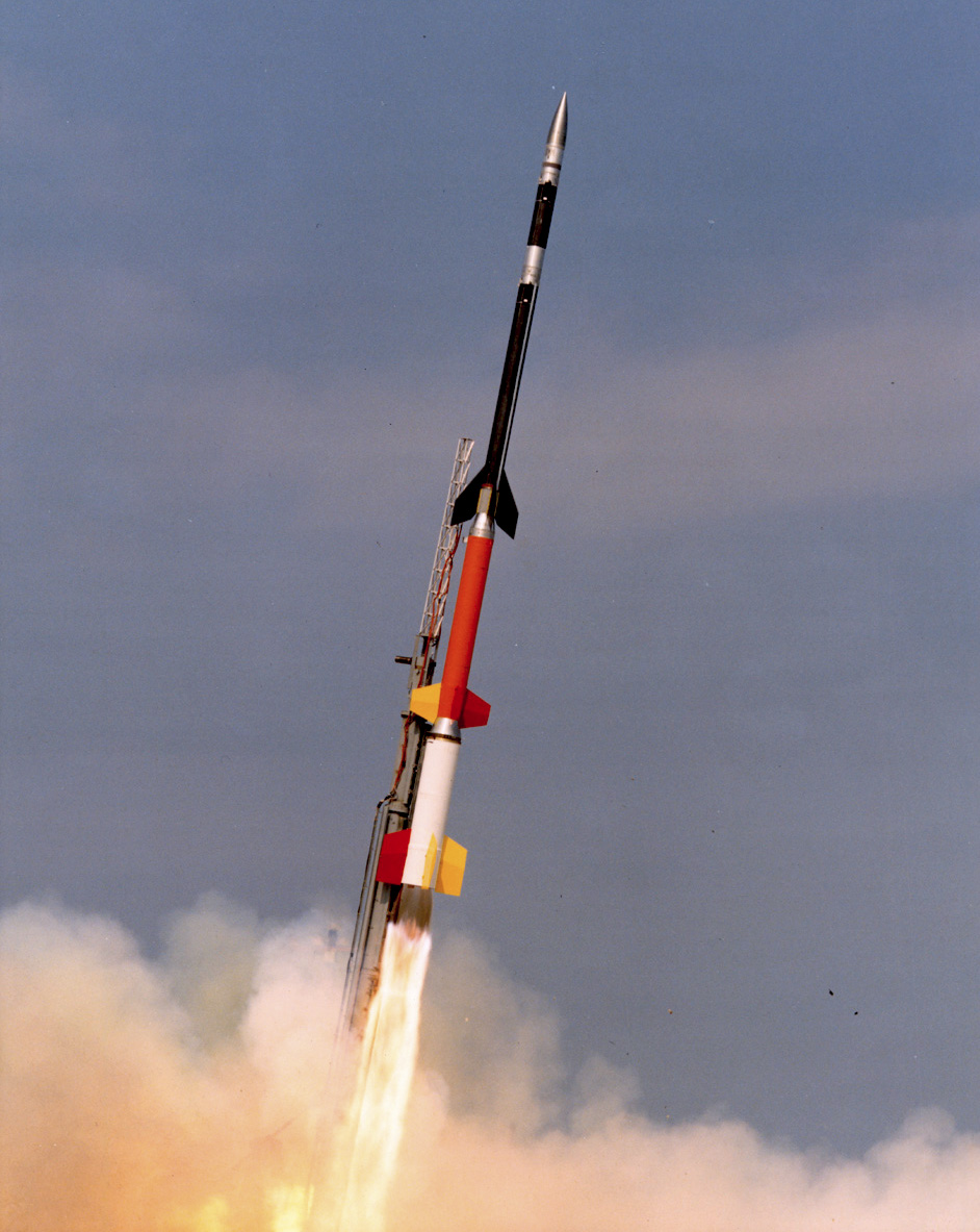
Multistage rocket
A multistage rocket or step rocket is a launch vehicle that uses two or more rocket stages, each of which contains its own engines and propellant. A tandem or serial stage is mounted on top of another stage; a parallel stage is attached alongside another stage. The result is effectively two or more rockets stacked on top of or attached next to each other. Two-stage rockets are quite common, but rockets with as many as five separate stages have been successfully launched.
By jettisoning stages when they run out of propellant, the mass of the remaining rocket is decreased. Each successive stage can also be optimized for its specific operating conditions, such as decreased atmospheric pressure at higher altitudes. This staging allows the thrust of the remaining stages to more easily accelerate the rocket to its final velocity and height.
In serial or tandem staging schemes, the first stage is at the bottom and is usually the largest, the second stage and subsequent upper stages are above it, usually decreasing in size. In parallel staging schemes solid or liquid rocket boosters are used to assist with launch. These are sometimes referred to as "stage 0". In the typical case, the first-stage and booster engines fire to propel the entire rocket upwards. When the boosters run out of fuel, they are detached from the rest of the rocket (usually with some kind of small explosive charge or explosive bolts) and fall away. The first stage then burns to completion and falls off. This leaves a smaller rocket, with the second stage on the bottom, which then fires. Known in rocketry circles as staging, this process is repeated until the desired final velocity is achieved. In some cases with serial staging, the upper stage ignites before the separation—the interstage ring is designed with this in mind, and the thrust is used to help positively separate the two vehicles.
Only multistage rockets have reached orbital speed. Single-stage-to-orbit designs are sought, but have not yet been demonstrated on Earth.
Multi-stage rockets overcome a limitation imposed by the laws of physics on the velocity change achievable by a rocket stage. The limit depends on the fueled-to-dry mass ratio and on the effective exhaust velocity of the engine. This relation is given by the classical rocket equation:
where:
The delta v required to reach low Earth orbit (or the required velocity of a sufficiently heavy suborbital payload) requires a wet to dry mass ratio larger than has been achieved in a single rocket stage. The multistage rocket overcomes this limit by splitting the delta-v into fractions. As each lower stage drops off and the succeeding stage fires, the rest of the rocket is still traveling near the burnout speed. Each lower stage's dry mass includes the propellant in the upper stages, and each succeeding upper stage has reduced its dry mass by discarding the useless dry mass of the spent lower stages.
A further advantage is that each stage can use a different type of rocket engine, each tuned for its particular operating conditions. Thus the lower-stage engines are designed for use at atmospheric pressure, while the upper stages can use engines suited to near vacuum conditions. Lower stages tend to require more structure than upper as they need to bear their own weight plus that of the stages above them. Optimizing the structure of each stage decreases the weight of the total vehicle and provides further advantage.
Hub AI
Multistage rocket AI simulator
(@Multistage rocket_simulator)
Multistage rocket
A multistage rocket or step rocket is a launch vehicle that uses two or more rocket stages, each of which contains its own engines and propellant. A tandem or serial stage is mounted on top of another stage; a parallel stage is attached alongside another stage. The result is effectively two or more rockets stacked on top of or attached next to each other. Two-stage rockets are quite common, but rockets with as many as five separate stages have been successfully launched.
By jettisoning stages when they run out of propellant, the mass of the remaining rocket is decreased. Each successive stage can also be optimized for its specific operating conditions, such as decreased atmospheric pressure at higher altitudes. This staging allows the thrust of the remaining stages to more easily accelerate the rocket to its final velocity and height.
In serial or tandem staging schemes, the first stage is at the bottom and is usually the largest, the second stage and subsequent upper stages are above it, usually decreasing in size. In parallel staging schemes solid or liquid rocket boosters are used to assist with launch. These are sometimes referred to as "stage 0". In the typical case, the first-stage and booster engines fire to propel the entire rocket upwards. When the boosters run out of fuel, they are detached from the rest of the rocket (usually with some kind of small explosive charge or explosive bolts) and fall away. The first stage then burns to completion and falls off. This leaves a smaller rocket, with the second stage on the bottom, which then fires. Known in rocketry circles as staging, this process is repeated until the desired final velocity is achieved. In some cases with serial staging, the upper stage ignites before the separation—the interstage ring is designed with this in mind, and the thrust is used to help positively separate the two vehicles.
Only multistage rockets have reached orbital speed. Single-stage-to-orbit designs are sought, but have not yet been demonstrated on Earth.
Multi-stage rockets overcome a limitation imposed by the laws of physics on the velocity change achievable by a rocket stage. The limit depends on the fueled-to-dry mass ratio and on the effective exhaust velocity of the engine. This relation is given by the classical rocket equation:
where:
The delta v required to reach low Earth orbit (or the required velocity of a sufficiently heavy suborbital payload) requires a wet to dry mass ratio larger than has been achieved in a single rocket stage. The multistage rocket overcomes this limit by splitting the delta-v into fractions. As each lower stage drops off and the succeeding stage fires, the rest of the rocket is still traveling near the burnout speed. Each lower stage's dry mass includes the propellant in the upper stages, and each succeeding upper stage has reduced its dry mass by discarding the useless dry mass of the spent lower stages.
A further advantage is that each stage can use a different type of rocket engine, each tuned for its particular operating conditions. Thus the lower-stage engines are designed for use at atmospheric pressure, while the upper stages can use engines suited to near vacuum conditions. Lower stages tend to require more structure than upper as they need to bear their own weight plus that of the stages above them. Optimizing the structure of each stage decreases the weight of the total vehicle and provides further advantage.