
Steel square
View on WikipediaThis article needs additional citations for verification. (July 2025) |
 | |
| Other names |
|
|---|---|
| Classification |
|
| Used with | |
The steel square is a tool used in carpentry. Carpenters use various tools to lay out structures that are square (that is, built at accurately measured right angles), many of which are made of steel, but the name steel square refers to a specific long-armed square that has additional uses for measurement, especially of various angles. It consists of a long, wider arm and a shorter, narrower arm, which meet at an angle of 90 degrees (a right angle). Today the steel square is more commonly referred to as the framing square or carpenter's square, and such squares are no longer invariably made of steel (as they were many decades ago); they can also be made of aluminum or polymers, which are light and resistant to rust.
The longer wider arm is 50 millimetres (2.0 in) wide, and is called the body; the shorter narrower arm, is 37 millimetres (1.5 in) wide, and is called the tongue. The square has many uses, including laying out common rafters, hip rafters and stairs.[1] It has a diagonal scale, board foot scale and an octagonal scale. On the newer framing squares there are degree conversions for different slopes and fractional equivalents.
Framing squares may also be used as winding sticks.
Body and tongue
[edit]In traditional timber frame joinery, mortises and tenons were typically 50 millimetres (2.0 in) wide and 50 millimetres (2.0 in) from the edge of the timber when working with softwoods, giving rise to the width of the body. Likewise, mortises and tenons were traditionally 37 millimetres (1.5 in) wide when working in hardwoods, explaining the width of the tongue. This allowed for quick layouts of mortise and tenon joints when working both hard and softwoods.
Use
[edit]Calibration
[edit]A steel square is self-proving and self-calibrating in that you can lay out a perpendicular line, flip the square over, and determine the size and direction of the error. The error can be corrected by opening or closing the angle with a center punch.[2]
Stair framing
[edit]
Stairs usually consist of three components. They are the stringer, the tread and the riser. The stringer is the structural member that carries the load of the staircase, the tread is the horizontal part that is stepped on, and the riser board is the vertical part which runs the width of the structure. There are many types of stairs: open, closed, fully housed, winding, and so on, to mention a few of them.
Laying out a staircase requires rudimentary math. There are numerous building codes to which staircases must conform. In an open area the designer can incorporate a more desirable staircase. In a confined area this becomes more challenging. In most staircases there is one more rise than there are treads.
- The rise (vertical measurement), and the run (horizontal measurement). The stringer will rest partially on the horizontal surface.
- This is a two-by-twelve piece of lumber. A framing square is placed on the lumber so that the desired rise and tread marks meet the edge of the board. The outline of the square is traced. The square is slid up the board until the tread is placed on the mark and the process is repeated.
- The board is cut along the dotted lines, and the top plumb cut and the bottom level cut are traced by holding the square on the opposite side.
- The stringer in this example has two pieces of tread stock. This allows for a slight overhang. There is also a space in between the boards. The bottom of the stringer must be cut to the thickness of the tread. This step is called dropping the stringer. After one stringer is cut this piece becomes the pattern that is traced onto the remaining stringers.
Roof framing
[edit]| 18" | 17" | 16" | 15" | 14" | 13" | 12" | 10" | 9" | 8" | |
|---|---|---|---|---|---|---|---|---|---|---|
| Common rafter length per foot run | 21.63" | 19.21" | 16.97" | 14.42" | ||||||
| Hip or valley rafter length per foot run | 24.74" | 22.65" | 20.78" | 18.76" | ||||||
| Difference in length of jacks 16 inch centers | 28.88" | 25.63" | 22.63" | 19.25" | ||||||
| Difference in length of jacks 24 inch centers | 43.25" | 38.44" | 33.94" | 28.88" | ||||||
| Side cut length of jack rafters | 6.69" | 7.5" | 8.5" | 10.00" | ||||||
| Side cut of hip rafter or valley rafter | 8.25" | 9.0" | 9.81" | 10.88" | ||||||
| This table shows five different types of rafter calculations and one table for marking an angle called the side cut or cheek cut. | ||||||||||
There is a table of numbers on the face side of the steel square; this is called the rafter table. The rafter table allows the carpenter to make quick calculations based on the Pythagorean theorem. The table is organized by columns that correspond to various slopes of the roof. Each column describes a different roof inclination (slope) and contains the following information:

- Common rafter per foot of run. The common rafter connects the peak of a roof (the ridge) to the base of a roof (the plate). This number gives the unit line length (hypotenuse) of the common rafter per twelve inches of horizontal distance (run).
- Hip or valley rafter per foot of run. The hip or valley rafter also connects the ridge to the plate, but lies at a 45-degree angle to the common rafter. This number gives the length of the hip or valley rafter per twelve inches of run.
- Difference in lengths jacks. The jack rafters lie in the same plane as the common rafter but connect the top plate (the wall) or ridge board to the hip or valley rafter respectively. Since the hip or valley rafter meets the ridge board and the common rafter at angles of 45 degrees, the jack rafters will have varying lengths when they intersect the hip or valley. Depending on the spacing of the rafters, their lengths will vary by a constant factor—this number is the common difference.
- This angle can be cut on the fly by aligning this given number on the body of the steel square and the twelve-inch mark on the tongue, and drawing a line along the tongue.
- Cutting hip and valley cripple rafters are all cut in a similar way.
-
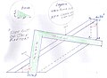
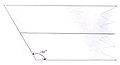
 The relationship between hip, jack and common rafters, and how they tie into the ridge and bottom plate. The rafters are fastened to the horizontal ridge board at the peak of the roof.
 -
 The side cut is the beveled angle of the hip or valley rafter that fits into the ridge board in this image.
 -
 Common and jack rafters all use twelve as the common reference to mark the plumb cut.
 -
 Hip and jack rafters use twelve as a common reference while aligning the desired pitch in the side cut column.
 -
 Hip and valley rafters use seventeen as the common reference for marking the plumb cut of a rafter.


Octagon scale
[edit]The octagon scale allows the user to inscribe an octagon inside a square, given the length of the side of the square. The markings indicate half the length of the octagon's sides, which can be set to a compass or divider. Arcs drawn from the midpoints of the square's sides will intersect the square at the vertices of the planned octagon. All that remains is to cut four triangular sections from the square.
-
 Octagon table located on the front side of the steel square.
 -
 Octagon table viewed from an aluminum square.
 -
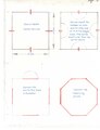 4 steps to draw Octagons.


Diagonal scale
[edit]Knee bracing is a common feature in timber framing to prevent racking under lateral loads. The diagonal scale is useful for determining the length of the a knee brace desired for a given distance from the joint between the post and beam.
-
 This is the location of the diagonal scale on the square.
 -
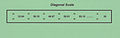 The diagonal scale gives the diagonal, or the hypotenuse, for the different legs of the triangle for which a brace is to be cut.

Calculators in roof framing
[edit]
In addition to use the square tool, construction calculators are also used to verify and determine roofing calculations. Some are programmed to calculate all side cuts for hip, valley and jack regular rafters to be exactly 45° for all rafter pitches. The rafter table is expressed in inches, and the higher the numerical value of the slope, the greater the difference between side cut angles within a given slope. Only a level roof, or a 0 slope will require a 45° angle side cut (cheek cut) for hip and jack rafters.
Side cut hip/valley rafter table
[edit]If a right triangle has two angles that equal 45° then the two sides are equidistant. The rafter is the hypotenuse and the legs or catheti of the triangle are the top wall plates of the structure. The side cut is located at the intersection of the given slope column and the side cut of the hip/valley row. The regular hip/valley rafter runs at a 45° angle to the common rafter and the unit of measurement is 12 inches of run. Regular hip/valley and jack rafters have different bevel angles within any given slope and the angle decreases as the slope increases.
| Legend | ||
|---|---|---|
| ||


The side cut of the hip/valley rafter = (Tangent)(12) = side cut in inches. The side cuts in the rafter table are all in a base 12. The arc tan can be determined from any given slope. Most power tools and angle measuring devices use 90° as 0° in construction. The complementary angles of the arc tan are used with tools like the speed square.
Side cut of jack rafters
[edit]The side cut is located at the intersection of the side cut of jack rafters row and the slope column on the Steel square. There is a row for the difference in length of jacks, 16 and 24 inch centers on the body. The tangents are directly proportional for both centers.

The tangent is in a base 12. The tangent x 12 = side cut of jack rafters. This corresponds to the side cut on the Steel square. The complementary angles of the arc tan are used on most angle measuring devices in construction. The tangent of hip, valley, and jack rafters are less than 1.00 in all pitches above 0°. An eighteen to twelve slope has a side cut angle of 29.07° and a two to twelve slope has a side cut angle of 44.56° for jack rafters. This is a variation of 15.5° between slopes.
Side cut angles versus slope
This is a reference table for side cuts versus slope. (only valid for 90 degrees eave angle) :
Slope expressed in inches
Slope 18/12 ==> 60,86 deg
Slope 17/12 ==> 60,10 deg
Slope 16/12 ==> 59,07 deg
Slope 15/12 ==> 57,99 deg
Slope 14/12 ==> 56,94 deg
Slope 13/12 ==> 55,88 deg
Slope 12/12 ==> 54,69 deg
Slope 11/12 ==> 53,49 deg
Slope 10/12 ==> 52,54 deg
Slope 9/12 ==> 51,25 deg
Slope 8/12 ==> 50,19 deg
Slope 7/12 ==> 49,17 deg
Slope 6/12 ==> 48,15 deg
Slope 5/12 ==> 47,33 deg
Slope 4/12 ==> 46,54 deg
Slope 3/12 ==> 45,90 deg
Slope 2/12 ==> 45,22 deg
Slope 1/12 ==> 45,10 deg
Slope 0/12 ==> 45,00 deg
Plumb cut of jack and common rafters
[edit]The plumb cut for jack and common rafters are the same angles. The level cut or seat cut is the complementary angle of the plumb cut. The notch formed at the intersection of the level and plumb cut Is commonly referred to as the bird's mouth .

Plumb cut of hip/valley rafters
[edit]The plumb cut of the hip/valley rafter is expressed in the formula. The level cut is the complementary angle or 90° minus the arc tan.

Irregular hip/valley rafters
[edit]The only Framing Square that has tables for unequal pitched roofs is the Chappell Universal Square, (patent #7,958,645). There is also a comprehensive rafter table for 6 & 8 sided polygon roofs (first time ever on a framing square). The traditional steel square's rafter table (patented April 23,1901) is limited in that it does not have tables that allow for work with unequal pitched roofs. Irregular hip/valley rafters are characterized by plan angles that are not equal or 45°. The top plates can be 90° at the outside corners or various other angles. There are numerous irregular h/v roof plans.
-
 irregular hip/valley gable roof plan.
 -
 irregular roof plan.
 -
 Intersecting irregular hip/valley gable roof plan.


Carpenter's square
[edit]In carpentry, a square is a guide for establishing right angles (90° angles) or mitre angles, usually made of metal. There are various types of square, such as speed squares, try squares and combination squares.
See also
[edit]References
[edit]Notes
[edit]- ^ Elliot, J. Hamilton (1910), Cobleigh, Rolfe (ed.), "Use of the Steel Square", Handy Farm Devices and How to Make Them, Orange Judd and Company.
- ^ "Framing Square Test & Repair". Inspectapedia. Retrieved 10 December 2021.
Bibliography
[edit]- Hodgson, Frederick T. (1880). The Carpenters' Steel Square and Its Uses. The Industrial Publication Company. LCCN 06036488.
- Siegele, H.H. (1981). The Steel Square. Sterling Publishing. ISBN 0-8069-8854-1.
- Ulrey, Harry F. (1972). Carpenters and Builders Library. Vol. 3. Theodore Audel. LCCN 74099760.
- Schuttner, Scott (1990). Basic Stairbuilding. Taunton Press. ISBN 0-942391-44-6.
- Spence, William P. (2000). Constructing Staircases Balustrades & Landings. Sterling Publishing. ISBN 0-8069-8101-6.
- Gochnour, Chris (February 2006). "11 Essential Measuring and Woodworking Tools". Fine Woodworking (182). Taunton Press: 75.
- Lanham, Wm. The Steel Square. Bath: E. A. Lovell.
- Falconer, John (1925). Ednie, John (ed.). The Steel Square. Carpentry and Joinery. Gresham.
- Sobon, Jack (1994). Build a classic timber-framed house : planning and design, traditional materials, affordable methods. Pownal, Vt. : Storey Communications. ISBN 0882668420.
| National | |
|---|---|
| Other | |
Steel square
View on GrokipediaOverview and History
Definition and Purpose
The steel square is a precision L-shaped tool essential in carpentry, consisting of a flat body—typically 24 inches long and 2 inches wide—and a perpendicular tongue, usually 16 inches long and 1.5 inches wide, both constructed from durable tempered steel and graduated in inches and fractions for accurate marking and measurement.[4][5] This design enables the tool to form a perfect 90-degree right angle, serving as a reliable guide for ensuring squareness in structural elements.[2][3] Its primary purposes include laying out right angles for framing walls, floors, and other assemblies; measuring board lengths and widths; scribing straight lines on lumber; and conducting geometric calculations, such as determining rafter angles and lengths for roofs or stair risers, all without requiring supplementary instruments.[1][2] In practice, carpenters position the square's corner against a workpiece to mark precise cuts or verify alignment, making it indispensable for tasks demanding exact perpendicularity and proportion.[3][6] Key advantages of the steel square stem from its robust construction, which resists bending, rust, and wear in demanding environments like steel-influenced modern construction, while offering versatility across rough framing and finish work.[7] The integration of multiple scales on its surfaces further enhances its utility for complex layouts, allowing quick computations for elements like hip rafters or braces directly on the tool.[2] The term "steel square" emerged in the 19th century to differentiate it from wooden predecessors, becoming a staple in North American carpentry traditions.[8][4]Historical Development
The steel square traces its origins to early precursors like wooden try squares used by ancient Egyptian woodworkers for verifying right angles and ensuring straight edges in construction and artifact production. These tools, comprising a blade and perpendicular stock, were prominently featured in New Kingdom carpentry, with depictions in 18th Dynasty tomb scenes such as that of Rekh-Mi-Re at Thebes, highlighting their role in precise joinery despite uncertain earlier origins.[9] In medieval Europe, wooden try squares served similar functions for basic right-angle checks in carpentry, evolving from simple L-shaped forms into more refined instruments by the 16th century, as evidenced in German prints illustrating their use in timber work.[10] The shift to steel marked a pivotal 19th-century innovation in the United States, driven by the Industrial Revolution's demand for durable, standardized tools. In 1814, Vermont blacksmith Silas Hawes created the first steel carpenter's square by forge-welding two thin strips of discarded saw steel at right angles, a process that addressed the limitations of wooden versions in accuracy and longevity; Hawes received a patent for an improved design in 1819, enabling widespread adoption in the 1820s and 1840s for precise building layouts.[11] This transition facilitated mass production and supported the era's expansion of mechanized woodworking, with the steel square becoming indispensable for tasks like framing during the post-Industrial building surge. The tool's utility was further popularized by Frederick Hodgson's 1883 treatise The Carpenters' Steel Square, and Its Uses, which systematically explained applications such as calculating rafter lengths and bevels, influencing carpentry education and practice.[12] By the early 20th century, post-World War II industrial advancements shifted production from labor-intensive hand-forging to efficient machine-stamping techniques, boosting output to meet the 1940s-1950s housing booms and reducing costs for widespread use.[13] The steel square contributed to late-19th-century balloon framing techniques, revolutionizing lightweight wood-frame construction from the 1860s to 1920. Into the 21st century, refinements like laser-etched markings emerged around the 2000s, drawing on laser technology developed since the 1960s to offer superior precision over traditional stamping.[14]Design and Components
Body and Tongue
The body of the steel square is the longer of its two arms, typically measuring 24 inches in length and 2 inches in width, enabling extended measurements and markings along the length of boards during framing tasks.[15] The outer edge of the body serves as the reference for heel marks, such as those used in positioning rafters on wall plates.[16] The tongue forms the shorter arm, perpendicular to the body at a precise 90-degree angle, with standard dimensions of 16 inches in length and 1.5 inches in width, allowing for accurate right-angle layouts and checks in construction work.[15] Its inner edge provides the alignment for toe marks, particularly in defining the seated portion of birdsmouth cuts on rafters. Both the body and tongue are constructed from tempered steel to ensure durability and resistance to bending under jobsite conditions, with a typical thickness of 1/16 inch. This material choice, often treated with a protective epoxy or clear finish, enhances rust resistance while maintaining structural integrity over prolonged use.[17] The arms are permanently joined at the heel via a riveted connection, which provides rigidity and maintains the 90-degree angle. While the imperial standard of 24 by 16 inches predominates in North American markets, international variants commonly feature metric dimensions of 60 cm for the body and 40 cm for the tongue to accommodate regional measurement preferences.[18]Scales and Markings
The edges of the steel square's body and tongue feature inch graduations for linear measurements, typically marked in increments of 1/16 inch on the outer edges and 1/8 inch on the inner edges to facilitate precise marking and cutting in carpentry tasks.[19][2] These graduations extend along both the outer and inner faces of the arms, allowing users to measure from multiple reference points while maintaining the tool's right-angle alignment. On the face of the body, rafter tables provide scales for determining roof pitches, typically numbered from 1 to 12 indicating inches of rise per foot of run.[2] The reverse side of the body includes the Essex board feet table, a tabular scale used to calculate lumber volume in board feet based on dimensions, aiding in material estimation for framing projects.[20] Markings on the steel square follow standardized layout conventions, beginning at the heel—the right-angle corner where the body and tongue meet—as the zero point, with directional arrows guiding measurements along the scales.[2] Common abbreviations, such as "C" for common rafter, appear adjacent to relevant scales to denote specific framing elements efficiently.[21] Manufacturing processes for these scales involve laser etching or stamping for durability and legibility, often with high-contrast black-filled engravings on a powder-coated or anodized steel surface to resist wear and improve visibility in various lighting conditions.[19][22] Some models incorporate unique features integrated with the markings, such as embedded level vials for quick plumb checks or protractor arcs along the edges for angle verification, enhancing the tool's versatility without additional equipment.[23][24]Basic Operation
Calibration
Steel squares undergo initial factory calibration during manufacturing to ensure the angle between the body and tongue forms a precise right angle, typically within tolerances of approximately 0.1 degrees based on measurements of commercial products.[25] This process involves precision stamping, grinding, and inspection using mechanical or optical comparators to verify squareness and scale accuracy before distribution.[26] Users should periodically verify the square's accuracy to account for potential damage or wear. One common technique is the line-scribing method: secure the square against a straight-edged board, such as the factory edge of plywood, and mark a line along the inner edge of the body or tongue using a pencil or marking knife; then flip the square over the same reference edge and mark a second line, checking if the lines perfectly align—if they diverge, the square is inaccurate.[27] Another reliable verification method employs the 3-4-5 Pythagorean triple: from the heel, mark 3 units along the tongue and 4 units along the body, then measure the hypotenuse between these points, which should equal exactly 5 units for a true right angle.[28] If verification reveals deviation, adjustment may be necessary, though steel's rigidity makes this uncommon and best limited to minor corrections. Place the square on a flat, solid surface and use a center punch and hammer to strike the heel—inside the corner to widen the angle (if under 90 degrees) or outside to narrow it (if over 90 degrees)—checking progress after each light tap to avoid over-correction.[29] For more significant inaccuracies, replacement is recommended over forcing adjustments, as excessive bending can compromise the tool's integrity.[30] Cross-checking during calibration can be performed with auxiliary tools for greater reliability. A calibrated combination square or machinist's square serves as a reference to align against the steel square's edges, confirming the 90-degree angle.[31] Modern digital angle finders offer precise electronic measurement, displaying deviations in degrees or minutes for fine verification.[32] To preserve calibration and overall condition, handle the steel square carefully to avoid drops or impacts that could warp the metal.[29] Regular maintenance includes cleaning the surfaces with a mild solvent and fine steel wool to remove debris or rust, followed by applying a light coat of oil or paste wax to protect against corrosion that might obscure markings or alter edges.[33]Fundamental Measuring and Marking Techniques
The steel square, also known as a framing square, serves as a precise tool for basic measurements by aligning its heel—the intersection of the body and tongue—at the end of a board or material edge. The outer edges of the body (typically 24 inches long) and tongue (16 inches long) feature graduated scales marked in sixteenths of an inch, enabling direct reading of lengths for marking with a pencil or utility knife along the desired scale line. This process ensures straight, accurate linear measurements without relying on additional tools for short spans.[2][34] Marking right angles begins by positioning the square's body or tongue flush against the straight edge of the workpiece, with the heel serving as the reference point for the 90-degree corner. Trace a line along the opposite arm using a sharp pencil, ensuring the square remains flat against the surface to maintain perpendicularity; for inside corners, align the inner faces of the arms, while outside corners use the outer faces. This technique is essential for squaring joints or edges, such as verifying that two boards meet at a true right angle by sighting along both arms to confirm alignment with the board edges.[5][34] For linear scaling, the square's fractional markings facilitate precise conversions, such as locating a 1/16-inch increment for fine cuts by counting along the scale from the heel. When dealing with spans exceeding the square's length, combine it with a tape measure by first marking the tape's endpoint with the square to square the line perpendicular to the board, then extending the measurement. This hybrid approach maintains accuracy over longer distances.[2] Common errors in using the steel square include parallax from tilting the tool, which distorts scale readings, and neglecting to account for saw kerf—the width of the blade removed during cutting—leading to undersized pieces; mitigate these by pressing the square firmly flat against the workpiece and marking the cut line slightly outside the final dimension to compensate for the kerf, typically 1/8 inch for most circular saws. Always verify squareness by drawing test lines from opposing sides of a reference point and measuring for equality.[30] Safety and best practices emphasize securing the workpiece with clamps or vises to prevent slipping during marking, which could cause inaccurate lines or injury from shifting material. Work on a stable, level surface and wear eye protection to guard against flying debris from scribing or subsequent cutting; for tasks like laying out stud locations on wall plates or marking uniform lengths for floor joists, double-check all marks against a tape measure for consistency.[35]Applications in Framing
Stair Framing
In stair framing, the steel square, also known as a framing square, serves as an essential tool for laying out the components of staircases, ensuring precise vertical risers and horizontal treads that comply with safety standards. Carpenters use it to mark consistent rise-run units on stringer boards, which support the stairs, by aligning the square's tongue for the riser height and the body for the tread depth. This method allows for accurate scribing of plumb (vertical) and level (horizontal) lines, facilitating cuts that create a stable, uniform staircase.[36] Key principles in stair framing revolve around the rise-run ratio, which dictates a maximum riser height of 7¾ inches (196 mm) (no minimum specified), with tread depths of at least 10 inches (254 mm), as specified in the International Residential Code (IRC) for residential applications. For commercial structures, the International Building Code (IBC) imposes stricter limits: a maximum riser of 7 inches and a minimum tread depth of 11 inches to enhance accessibility and safety. The steel square enables marking these equal units by setting stair gauges or clamps on the tongue and body to replicate the dimensions repeatedly, preventing cumulative errors in multi-step layouts. For stringer layout, the process begins by placing the steel square on the edge of a 2x12 board, with the desired rise (e.g., 7¼ inches) along the tongue and the run (e.g., 10½ inches) along the body, positioned about 6 inches from the end to account for the top notch. Marks are drawn along the inner edges of the square for the first step, then the square is "stepped" along the board—aligning the previous run mark with the new rise position—to transfer multiple units efficiently. Adjustments for the first riser often subtract the tread thickness (typically 1½ inches) to ensure the top step aligns properly with the floor level.[36] Tread and riser cuts involve scribing plumb lines from the run marks to the board's edge using the square's 90-degree angle for vertical accuracy, and level lines across the risers for horizontal precision. The total stringer length required for the board can be calculated using the Pythagorean theorem applied to the overall rise and run: $ L = \sqrt{R^2 + T^2} $, where $ R $ is the total rise (number of risers × individual rise) and $ T $ is the total run (number of treads × individual run), ensuring the lumber is sufficiently long before cutting.[36] For adjustments in landings or winder stairs, irregular spacing is handled by making temporary marks with the steel square to establish baseline rise-run units, then modifying angles or offsets manually for turns, often using the square's diagonal edges or additional protractors for non-standard plumb cuts. This technique accommodates space constraints in multi-flight stairs without compromising overall uniformity.[37] Stair framing practices became standardized in the early 20th century with the adoption of model building codes to address fire safety and accessibility concerns arising from 19th-century urban fires that highlighted egress risks. In residential settings, these codes emphasize comfort for home use with slightly more flexible ratios, while commercial applications prioritize higher traffic loads with tighter tolerances, as seen in post-1900 industrial building regulations.Roof Framing
In roof framing, the steel square plays a central role in determining and marking the angles and lengths required for structural elements like rafters, ensuring accurate fits for various roof configurations. Basic roof types include gable roofs, which feature a triangular end profile with sloping sides meeting at a ridge, and hip roofs, where all sides slope downward to the walls without vertical ends. Roof pitch, defined as the vertical rise over horizontal run expressed as a ratio (e.g., 6/12 indicates 6 inches of rise per 12 inches of run), is a key parameter calculated and marked using the square's scales to establish the roof's slope.[38][39] For common rafter layout in gable or shed roofs, the steel square's rafter table on the inner edge of the body is aligned with the desired pitch, such as placing the 12 mark on the tongue against the rise number (e.g., 6 for a 6/12 pitch) to step off the run in 12-inch increments along the rafter stock. This method transfers the pitch directly to the material, allowing carpenters to mark plumb cuts at the ridge and birdsmouth notches—triangular seats for seating on wall plates—while accounting for overhangs like eaves. The square's percent-of-rise scale can briefly verify the slope angle for consistency during layout.[21] Hip and valley rafters, which run diagonally at roof corners or intersections, integrate with common rafters but require adjustments for shorter effective lengths due to plan offsets from the building's footprint. Using the steel square, carpenters mark the side-cut bevels (typically 45 degrees for square buildings) on the rafter's face and adjust the plumb cut angle to match the pitch, ensuring proper seating at the ridge and wall plates; valley rafters, mirroring hips but sloping inward, follow similar bevel techniques to form watertight junctions.[21] The steel square aids load considerations by facilitating even spacing of rafters, typically 16 or 24 inches on center, which distributes weight uniformly to prevent sagging or failure under snow, wind, or dead loads as required by the International Residential Code (IRC). Per IRC Section R802.3, rafters must be framed opposite each other at the ridge with no more than 1.5 inches offset, and the square's precise markings ensure compliance for structural integrity without over-spanning.[39] In case studies, a simple shed roof—one-sided with a single slope—relies on the steel square for straightforward pitch marking and birdsmouth cuts on a minimal rafter set, ideal for outbuildings with low complexity. Conversely, a gambrel roof, featuring two pitches per side for added headroom, demands iterative square layouts to transition between the steeper lower slope and shallower upper one, highlighting the tool's versatility in multi-plane framing. Modern supplements like speed squares, compact triangular versions of the steel square, often assist in quick angle checks during these applications.[40]Specialized Scales and Calculations
Octagon and Diagonal Scales
The octagon scale is located on the face of the tongue of the steel square and enables carpenters to lay out regular eight-sided polygons on square stock, such as for column bases or decorative posts.[41][42] To use it, first mark the centers of each side on the square material whose width equals the desired octagon side length . Set dividers to the marking on the octagon scale corresponding to (typically the distance between the numbered mark and the adjacent dot, representing the offset ). Place one divider point at the end of a centerline on the material and scribe an arc to mark the cut point on the adjacent side; repeat for all four centerlines on both ends of the stock. Connect the corresponding marks with straight lines to form the octagon sides.[41][42] This method derives from the geometric proportions of a regular octagon inscribed in a square, where the offset is calculated as , ensuring equal sides without additional computations.[41] For example, on a 6-inch square post, the scale indicates an offset of approximately 1.24 inches, yielding an octagon with 6-inch sides suitable for trim work.[42] The scale is limited to regular octagons on square stock up to the tongue's 16-inch length and provides markings in 1/16-inch increments for precision, though larger shapes may require scaling the proportions mathematically.[41][42] Applications include creating symmetrical polygonal elements for decorative moldings or barrel vault segments, where sequential marking ensures uniformity.[42] The diagonal scale, also known as the brace scale, is positioned on the reverse side of the tongue (shorter arm) of the steel square and facilitates measuring hypotenuses for 45-degree right triangles, converting equal leg lengths to diagonal measurements.[43] To apply it, identify the pair of equal leg lengths (e.g., 12 inches) on the scale's left and right columns, then read the corresponding diagonal value from the center column (e.g., 16.97 inches). This allows direct transfer to material for cutting braces or diagonals without a calculator.[43] The scale's values are based on the Pythagorean theorem for isosceles right triangles, where the hypotenuse for leg length , providing triplets like 12/12/16.97 or 10/10/14.14.[43] For instance, in laying out a square frame's diagonal brace, a 54-unit leg yields a 76.37-unit brace, ensuring structural squareness.[43] This scale supports applications in non-structural polygons, such as irregular decorative trim requiring 45-degree diagonals, or verifying proportions in vaulted elements.[43] It assumes equal legs for accuracy and is marked to 1/16-inch precision, but deviates for non-45-degree angles, limiting it to regular geometric layouts.[43]Rafter Length and Cut Calculators
The steel square includes specialized tables etched on the face of the body to facilitate rafter length determinations and basic cut orientations in standard roof framing, enabling efficient on-site computations for common, hip, and valley rafters. These tables express measurements as unit lengths per foot of horizontal run, calibrated to common roof pitches denoted as rise inches per 12 inches of run (e.g., 4/12 for a 4-inch rise). By providing precomputed multipliers, they eliminate the need for manual trigonometric solving, streamlining the process from pitch selection to material cutting.[44] The common rafter table, positioned as the primary row, delivers the hypotenuse length for rafters spanning from wall plate to ridge board per foot of run. For a 12/12 pitch, this yields 16.97 inches per foot of run, derived from the Pythagorean theorem applied to the right triangle formed by the run (12 inches) and rise (12 inches). To compute the full length, the unit value is multiplied by the total run (typically half the building span), with deductions for ridge board thickness (e.g., 0.75 inches for a nominal 2x board) and additions for eave overhangs. This table supports pitches from low slopes like 4/12 up to steep 12/12, ensuring applicability across residential framing.[45][46] Adjacent to it, the hip and valley rafter table accounts for the extended path at roof corners or valleys, where the effective run incorporates a diagonal offset (approximately √2 times the common run for 90-degree intersections). Values are adjusted accordingly; for the same 12/12 pitch, the unit length is 20.78 inches per foot of common run, reflecting the compound geometry. The basis follows length = common length × (hip run factor), where the factor integrates the offset (e.g., 17 inches diagonal run per 12 inches common for perpendicular walls), yielding lengths roughly 20-25% longer than commons depending on pitch. Usage mirrors the common table: multiply by the common run, then adjust for intersections.[47] To use these tables, first identify the roof pitch (e.g., via level measurement or plans), locate the corresponding column on the body face, and read the unit length from the appropriate row. Multiply by the run in feet to obtain the theoretical length, then employ the square's numbered scales—aligning the tongue to the rise number and body to 12 for plumb cuts, or reverse for level seat cuts at the birdsmouth—to mark angles directly on the lumber. This integrated approach ensures plumb (vertical) and level (horizontal) orientations without additional tools. For pitches 4/12 to 12/12, the tables maintain high accuracy grounded in trigonometry, where unit length = run × sec(θ) and θ = arctan(rise/run), with rise = run × tan(θ); deviations are negligible for standard framing tolerances under 1/16 inch per foot. Representative unit lengths include:| Pitch | Common Rafter (inches per foot run) | Hip/Valley Rafter (inches per foot run) |
|---|---|---|
| 4/12 | 12.65 | 17.44 |
| 6/12 | 13.42 | 18.00 |
| 8/12 | 14.42 | 18.76 |
| 10/12 | 15.62 | 19.70 |
| 12/12 | 16.97 | 20.78 |