
Community hub
Recent from talks
Contribute something
Nothing was collected or created yet.
Sprocket
View on Wikipedia

A sprocket,[1] sprocket-wheel[2] or chainwheel is a profiled wheel with teeth that mesh with a chain, rack or other perforated or indented material.[3][4] The name 'sprocket' applies generally to any wheel upon which radial projections engage a chain passing over it. It is distinguished from a gear in that sprockets are never meshed together directly, and differs from a pulley in that sprockets have teeth and pulleys are smooth except for timing pulleys used with toothed belts.
Sprockets are used in bicycles, motorcycles, tracked vehicles, and other machinery either to transmit rotary motion between two shafts where gears are unsuitable or to impart linear motion to a track, tape etc. Perhaps the most common form of sprocket may be found in the bicycle, in which the pedal shaft carries a large sprocket-wheel, which drives a chain, which, in turn, drives a small sprocket on the axle of the rear wheel. Early automobiles were also largely driven by sprocket and chain mechanism, a practice largely copied from bicycles.
Sprockets are of various designs, a maximum of efficiency being claimed for each by its originator. Sprockets typically do not have a flange. Some sprockets used with timing belts have flanges to keep the timing belt centered. Sprockets and chains are also used for power transmission from one shaft to another where slippage is not admissible, sprocket chains being used instead of belts or ropes and sprocket-wheels instead of pulleys. They can be run at high speed and some forms of chain are so constructed as to be noiseless even at high speed.
Usage
[edit]The term 'sprocket' originally applied to the projection from the wheel that caught on the chain and provided the drive to it[citation needed]. The overall wheel was then termed a 'sprocket wheel'. With time and common use of these devices, the overall wheel became known as a sprocket. The earlier uses would now be seen as archaic.
Transportation
[edit]In the case of bicycle chains, it is possible to modify the overall gear ratio of the chain drive by varying the diameter (and therefore, the tooth count) of the sprockets on each side of the chain. This is the basis of derailleur gears. A multi-speed bicycle, by providing two or three different-sized driving sprockets and up to 12 (as of 2018) different-sized driven sprockets, allows up to 36 different gear ratios. The resulting lower gear ratios make the bike easier to pedal up hills while the higher gear ratios make the bike more powerful to pedal on flats and downhills. In a similar way, manually changing the sprockets on a motorcycle can change the characteristics of acceleration and top speed by modifying the final drive gear ratio. The final drive gear ratio can be calculated by dividing the number of teeth on the rear sprocket by the number of teeth on the counter-shaft sprocket. With respect to the stock gearing on a motorcycle, installing a smaller counter-shaft sprocket (fewer teeth), or a larger rear sprocket (more teeth), produces a lower gear ratio, which increases the acceleration of the motorcycle but decreases its top speed. Installing a larger counter-shaft sprocket, or a smaller rear sprocket, produces a higher gear ratio, which decreases the acceleration of the motorcycle but increases its top speed.
Chain tracked vehicles
[edit]
(Leclerc battle tank, 2006)
In the case of vehicles with caterpillar tracks the engine-driven toothed-wheel transmitting motion to the tracks is known as the drive sprocket and may be positioned at the front or back of the vehicle, or in some cases both. There may also be a third sprocket, elevated, driving the track.
Film and paper
[edit]
Sprockets are used in the film transport mechanisms of movie projectors and movie cameras.[5] In this case, the sprocket wheels engage film perforations in the film stock. Sprocket feed was also used for punched tape and is used for paper feed to some computer printers.
See also
[edit]- Bicycle chain
- Bicycle gearing
- Chain drive
- Cogset (as used in bicycle gearing)
- Gear train
- Glossary of cycling
- Mechanical advantage
- Rack and pinion
- Roller chain (or "sprocket chain")
- Toad the Wet Sprocket
- Toothed belt
References
[edit]- ^ "Sprocket - Definition". Merriam-Webster. Retrieved 2011-11-14.
sprocket, n. 1: a toothed wheel whose teeth engage the links of a chain
- ^ Oxford English Dictionary (2nd ed.). Oxford University Press. 1989.
sprocket, n. 2. b. ellipt. A sprocket-wheel, esp. that of a cycle; and (Cinematogr.), one that propels film by engaging with perforations along its edge.
- ^ The Encyclopedia Americana: a library of universal knowledge, sprocket. pg 460
- ^ Elements of machine design By Oscar Adolph Leutwiler
- ^ Motion picture handbook By Frank Herbert Richardson
External links
[edit]| Frame |  | |
|---|---|---|
| Wheels | ||
| Drivetrain | ||
| Cabling | ||
| Peripherals | ||
Sprocket
View on GrokipediaOverview
Definition
A sprocket is a profiled wheel featuring teeth or cogs designed to mesh with a chain, track, or other perforated material, enabling the transmission of mechanical power or motion between rotating shafts.[5] This component is fundamental in systems where direct contact between wheels is impractical, allowing for efficient engagement without slippage.[6] Unlike gears, which interlock directly with one another to transfer motion through tooth-to-tooth contact, sprockets do not mesh with each other but instead engage with an intermediary flexible element like a chain.[5] Similarly, sprockets differ from pulleys, which are typically smooth-rimmed wheels that rely on friction with belts for power transmission, though exceptions exist for toothed pulleys paired with specialized belts.[5] These distinctions highlight the sprocket's specialized role in chain-driven mechanisms, ensuring precise and reliable motion transfer.[6] At its core, a sprocket converts rotary motion into linear motion—or vice versa—by gripping the links or perforations of the mating material as it rotates, thereby driving connected components in machinery such as bicycles or conveyor systems.[5]Principles of Operation
A sprocket functions through the precise meshing of its teeth with the links or rollers of a chain, creating a positive drive that prevents slippage and ensures reliable motion transfer. During operation, as the sprocket rotates, its teeth sequentially engage the chain's rollers or bushings, pulling the chain along the tight span while the disengaging teeth release smoothly from the slack span. This interlocking action maintains chain tension and converts rotational motion into linear chain movement, with the tooth profile designed to cradle the chain components for minimal friction and maximal contact.[7] Force transmission in a sprocket-chain system occurs via the tangential pull exerted by the engaged teeth on the chain, converting input torque into output power. The torque applied to the driving sprocket generates a chain tension force that propagates through the system, with power calculated as the product of torque and angular velocity: where is the angular velocity in radians per second. This relationship holds for both driving and driven sprockets, assuming efficient meshing, and enables the system to transmit high loads over variable distances while maintaining a constant velocity ratio determined by the sprocket tooth counts.[8] Kinematically, sprockets operate within chain drives by aligning the chain's path to the sprocket's pitch circle diameter, which is the theoretical circle passing through the centers of the chain rollers in mesh and defined as , where is the chain pitch and is the number of teeth.[9] This diameter ensures uniform engagement and determines the drive's speed ratio. The chain wrap angle, typically at least 120° on the smaller sprocket, dictates the extent of tooth-chain contact, influencing stability and load distribution; insufficient wrap can lead to vibrations, while optimal angles (e.g., 180° for idlers) promote even force sharing across multiple teeth.[7] Common wear mechanisms in sprockets arise from repeated loading, including tooth deformation where high tensile forces cause elastic or plastic bending of the teeth, unevenly distributing stress and accelerating fatigue. Under heavy loads, this deformation can misalign subsequent engagements, compounding wear on both sprocket and chain components.[10]History
Early Development
The earliest precursors to modern sprockets appeared in ancient mechanisms as toothed wheels designed to transmit motion. In the 3rd century BCE, the Greek engineer Philo of Byzantium described devices incorporating chain drives powered by sprocket wheels, such as in repeating crossbows and other pneumatic machines, where flat-linked chains engaged with toothed wheels to automate bolt loading.[3] These innovations built on earlier Hellenistic engineering, including water-raising devices and catapults that utilized rudimentary geared systems for power transfer.[11] Sketches by Leonardo da Vinci in the early 1500s depicted early steel chain designs paired with toothed wheels.[3] The development of practical chain drive sprockets emerged in the early 19th century amid the Industrial Revolution's demand for reliable power transmission. In 1800, British inventor James Fussell patented an early form of roller chain, which engaged with sprockets to reduce friction in mechanical linkages, marking a shift from rope or leather belts to more durable systems.[12] James Slater's 1864 invention of a transmission chain with rollers specifically for sprocket engagement marked a pivotal advancement in reliable power transfer.[3] A pivotal advancement came in 1880 when Swiss-born engineer Hans Renold patented the bush-roller chain in Manchester, England, featuring precision-formed sprockets with an improved curved tooth profile that minimized wear and enabled higher loads, particularly for emerging bicycle applications.[13] Renold's design transformed sprockets from experimental components into standardized industrial elements, influencing chain drives in factories and early mechanized transport. During the late 19th century, sprockets saw rapid integration into steam-powered machinery and the burgeoning bicycle industry, driven by patents that addressed efficiency in power transmission. Renold's sprockets were quickly adopted in textile mills and light engineering works, where they powered conveyor systems and auxiliary drives in steam engines, offering superior grip over flat belts in humid environments.[3] In bicycles, the safety model's chain drive—popularized from the mid-1880s—relied on Renold-style sprockets to connect pedals to rear wheels, enabling safer, lower designs that fueled the global cycling boom.[12] However, early implementations faced significant hurdles due to material constraints; cast iron and early steel alloys lacked sufficient tensile strength, resulting in frequent tooth breakage under high-torque loads from steam reciprocation or pedaling stresses.[14] These limitations often necessitated oversized sprockets or frequent replacements, constraining applications until metallurgical improvements in the 1890s.[15]Modern Advancements
In the early 20th century, the adoption of bush roller chains, originally patented by Hans Renold in 1880, revolutionized power transmission by providing greater durability and efficiency compared to earlier chain designs, enabling widespread use in industrial machinery and emerging automotive applications.[16] Following World War II, the automotive sector saw significant advancements with the introduction of hardened steel sprockets, which featured case-hardened teeth to withstand higher loads and reduce wear in engine timing systems, supporting the postwar boom in vehicle production.[17] Material innovations progressed throughout the century, with a shift toward advanced alloys such as case-hardened carbon steel by the mid-1900s, offering improved strength and resistance to fatigue in high-stress environments.[18] By the 1980s, the development of engineered plastic sprockets, often using materials like UHMW polyethylene, emerged for lightweight, corrosion-resistant applications in conveyors and low-load systems, as evidenced by patents for multi-tooth plastic designs that addressed temperature variability in industrial settings.[19] These plastics reduced weight by up to 50% compared to steel equivalents while maintaining sufficient tooth engagement for non-extreme conditions.[17] Manufacturing techniques advanced dramatically with the integration of computer numerical control (CNC) machining in the late 20th century, allowing for precise tooth profiling and custom geometries that minimized backlash and improved chain alignment.[20] Since the 2000s, additive manufacturing via 3D printing has enabled rapid prototyping of bespoke sprockets for robotics, using materials like nylon or ABS to produce complex, lightweight components with tolerances under 0.1 mm, facilitating agile design iterations in automated systems.[21] In recent years up to 2025, sprocket technology has incorporated Industry 4.0 principles through the embedding of smart sensors, such as vibration and temperature monitors, directly into chain drives for real-time predictive maintenance, reducing unplanned downtime by detecting wear patterns before failure.[22] These IoT-enabled systems analyze data from sprocket engagements to forecast maintenance needs, with adoption growing in manufacturing to achieve up to 30% efficiency gains in roller chain operations.[23]Design and Types
Components and Materials
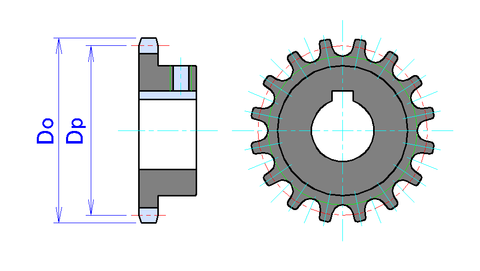
A sprocket's core components include the hub, bore, spokes or web structure in larger designs, and the teeth arranged around the periphery. The hub serves as the central mounting feature, providing structural support and attachment to the shaft; common configurations are Type A (a plain plate without hub extension for minimal applications), Type B (hub extension on one side), Type C (equal hub extensions on both sides for balanced loading), and Type D (a plate sprocket bolted to a detachable hub for adjustability). The bore is the central hole through the hub, sized to fit the drive shaft, and typically features fittings such as keyways for torque transmission or setscrews for securement. In larger sprockets, spokes or radial arms connect the hub to the outer rim, reducing weight and material use while maintaining rigidity against rotational stresses. The teeth are symmetrically arranged along the outer circumference on a pitch circle, with the number of teeth determining the gear ratio and engagement with the chain links. Material selection for sprockets depends on load requirements, environmental conditions, and cost. Carbon steel, often in grades like 1045 or 40Cr, is widely used for its high durability and resistance to wear in heavy-duty applications, providing a strong tooth surface that withstands friction. Stainless steel is preferred for corrosion-resistant environments, such as marine or chemical processing, where it maintains integrity without additional coatings. For low-load, lightweight, or noise-sensitive uses, polymers like nylon, ultra-high-molecular-weight polyethylene (UHMW), acetal (POM), or polyurethane offer advantages including reduced chain wear, chemical resistance, and quieter operation compared to metals. Sprocket sizes vary significantly by application, with pitch diameters ranging from a few millimeters for precision uses like film projectors (e.g., 16mm to 35mm film sprockets around 20-60mm) to several meters for industrial conveyor systems. Bore diameters typically span from 3/4 inch to 6 inches or more in standard roller chain sprockets, with custom options up to larger sizes; common bore types include keyed (with a keyway and key for positive drive), splined (multiple ridges for high-torque transmission without slippage), and tapered (using bushings for easy installation and removal on varying shaft sizes). Sprockets are manufactured through processes tailored to size and material, including machining from bar stock for precision small-to-medium units, casting for economical production of complex shapes, and forging for superior strength in high-stress components. Heat treatment, such as case hardening or quenching and tempering, is applied to steel sprockets to enhance surface hardness and wear resistance, extending service life under abrasive conditions.Tooth Profiles and Standards
The tooth geometry of sprockets is engineered to facilitate smooth engagement and disengagement with the chain, minimizing wear and vibration. For standard roller chain sprockets, the profile consists of a seating curve at the root and a working (or topping) curve on the flanks, both formed by circular arcs tailored to the chain's roller diameter. The seating curve radius is calculated as approximately half the roller diameter plus a small clearance (e.g., R = 0.5025 × Dr + 0.0015 inches, where Dr is the roller diameter), ensuring the roller seats properly without binding. The topping curve radius is derived to reduce impact during entry, typically using formulas that incorporate the chain pitch P, number of teeth N, and roller diameter for precise flank shaping. Tooth thickness at the pitch line is generally about 0.95P for compatibility, measured across the narrowest point to allow clearance, while the pitch measurement aligns with the chain's roller center distance to prevent slippage.[24] Sprocket sizing and compatibility are standardized by the American National Standards Institute (ANSI) under ASME B29.1-2011 for precision power transmission roller chains, attachments, and sprockets, which defines chain designations from #25 (1/4-inch pitch) to #240 (1.5-inch pitch) and specifies the Type II tooth form for most applications. This form ensures interchangeable components across manufacturers, with tolerances on tooth dimensions, hub configurations, and maximum bore sizes to support loads up to tens of thousands of pounds tensile strength. The international equivalent, ISO 606:2015, provides metric equivalents (e.g., 06B for #35 chain) and aligns closely with ANSI for global compatibility, emphasizing pitch accuracy and roller fit. Key engagement factors include matching the chain pitch to the sprocket's geometry, with the pitch diameter D serving as the fundamental metric for velocity ratio and wrap angle:where P is the chain pitch and N is the number of teeth. This equation derives from the chordal action of the chain, ensuring rollers align with tooth spaces; for example, a 25-tooth sprocket with 1/2-inch pitch yields D ≈ 4.00 inches, optimizing power transmission efficiency above 97% at moderate speeds. Variations in sprocket design, such as double-pitch models, adjust tooth spacing to half the standard pitch for longer-link chains, but maintain the same core profile principles.[25] In contrast, silent chain (inverted tooth) sprockets employ an involute tooth profile to mesh with the chain's toothed plates, differing from the arc-based design of roller chain sprockets by providing gear-like conjugation for reduced noise and higher speeds up to 5,000 rpm. Governed by ASME B29.2M-2007, these standards specify pitches from 3/8 inch to 1-1/2 inches and involute angles (typically 14.5° or 20° pressure angle) to minimize polygonal action, addressing limitations in roller chain standards by enabling broader width configurations without separate roller sizing.[26][27]