Hubbry Logo
Liquid-ring pumpLiquid-ring pumpMain
Open search
Liquid-ring pump
Community hub
Liquid-ring pump
logo
8 pages, 0 posts
0 subscribers
Be the first to start a discussion here.
Liquid-ring pump
Liquid-ring pump
from Wikipedia
The input port of this liquid-ring pump can be seen at the right side, while the output port is partially obscured at the left. The liquid seal is depicted in blue.

A liquid-ring pump is a rotating positive-displacement gas pump, with liquid under centrifugal force acting as a seal.

Description of operation

[edit]

Liquid-ring pumps are typically used as vacuum pumps, but can also be used as gas compressors. The function of a liquid-ring pump is similar to a rotary vane pump, with the difference being that the vanes are a rigid part of the rotor and churn a rotating ring of liquid to form the compression-chamber seal. They are an inherently low-friction design, with the rotor being the only moving part. Sliding friction is limited to the shaft seals.[1] Liquid-ring pumps are typically powered by an induction motor.

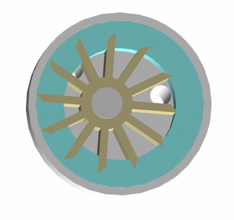
The liquid-ring pump compresses gas by rotating a vaned impeller located eccentrically within a cylindrical casing. Liquid (often water) is fed into the pump, and by centrifugal acceleration forms a moving cylindrical ring against the inside of the casing. This liquid ring creates a series of seals in the spaces between the impeller vanes, which form compression chambers. The eccentricity between the impeller's axis of rotation and the casing geometric axis results in a cyclic variation of the volume enclosed by the vanes and the ring.

A gas (often air) is drawn into the pump through an inlet port in the side of the casing. The gas is trapped in the compression chambers formed by the impeller vanes and the liquid ring. The reduction in volume caused by the impeller rotation compresses the gas, which exits through the discharge port in the side of the casing.

The compressed gas at the discharge of pump contains a small amount of the working fluid, which is usually removed in a vapor–liquid separator.

History

[edit]

The earliest liquid-ring pumps date from 1903, when a patent was granted in Germany to Siemens-Schuckert. US Patent 1,091,529, for liquid-ring vacuum pumps and compressors, was granted to Lewis H. Nash in 1914.[2] They were manufactured by the Nash Engineering Company in Norwalk, Connecticut, US. Around the same time in Austria, Patent 69274 was granted to Siemens-Schuckertwerke for a similar liquid-ring vacuum pump.

Applications

[edit]

These simple, but highly reliable pumps have a variety of industrial applications. They are used to maintain condenser vacuum on large steam-turbine generator sets by removing incondensable gasses, where vacuum levels are typically 30–50 mbar. They are used on paper machines to dewater the pulp slurry and to extract water from press felts. Another application is the vacuum forming of molded paper-pulp products (egg cartons and other packaging). Other applications include soil remediation, where contaminated ground water is drawn from wells by vacuum. In petroleum refining, vacuum distillation also makes use of liquid-ring vacuum pumps to provide the process vacuum. In the plastic extrusion industry they are used for degassing. Liquid-ring compressors are often used in vapor recovery systems.

Design

[edit]

Single- and multi-stage

[edit]
Single-stage vacuum pump

Liquid-ring systems can be single- or multistage. Typically a multistage pump will have up to two cascaded compression stages on a common shaft. In vacuum service, the attainable pressure reduction is limited by the vapor pressure of the ring-liquid. As the generated vacuum approaches the vapor pressure of the ring-liquid, the increasing volume of vapor released from the ring-liquid diminishes the remaining vacuum capacity. The efficiency of the system declines as the limit is approached.

Single-stage vacuum pumps typically produce vacuum to 35 torr (mm Hg) or 47 millibars (4.7 kPa), and two-stage pumps can produce vacuum to 25 torr, assuming air is being pumped and the ring-liquid is water at 15 °C (59 °F) or less. Dry air and 15 °C sealant-water temperature is the standard performance basis, which most manufacturers use for their performance curves.

Recirculation of ring-liquid

[edit]

Some ring-liquid is also entrained with the gaseous discharge stream. This liquid is separated from the gas stream by other equipment external to the pump. In some systems, the discharged ring-liquid is cooled by a heat exchanger or cooling tower, and then returned to the pump casing. In some recirculating systems, contaminants from the gas become trapped in the ring-liquid, depending on system configuration. These contaminants become concentrated as the liquid continues to recirculate, and eventually could cause damage and reduced life of the pump. In this case, filtration systems are required to ensure that contamination is kept to acceptable levels.

In non-recirculating systems, the discharged hot liquid (usually water) is treated as a waste stream. In this case, fresh cool water is used to make up the loss. Environmental considerations are making such "once-through" systems increasingly rare.

Liquid selection

[edit]

Liquid-ring vacuum pumps can use any liquid compatible with the process as the sealant liquid, provided it has the appropriate vapor pressure properties. Although the most common sealant is water, almost any liquid can be used. The second most common sealant liquid is oil. Since oil has a very low vapor pressure, oil-sealed liquid-ring vacuum pumps are typically air-cooled. For dry chlorine gas applications, concentrated sulfuric acid is used as the sealant.

The ability to use any liquid allows the liquid-ring vacuum pump to be ideally suited for solvent (vapor) recovery. For example, if a process such as distillation or a vacuum dryer is generating toluene vapors, then it is possible to use liquid toluene as the sealant, provided the cooling water is cold enough to keep the vapor pressure of the sealant liquid low enough to pull the desired vacuum.[3]

Ionic liquids in liquid-ring vacuum pumps can lower the vacuum pressure from about 70 mbar to below 1 mbar.[4]

References

[edit]
Revisions and contributorsEdit on WikipediaRead on Wikipedia
from Grokipedia
A liquid-ring pump is a rotary positive displacement machine that utilizes a liquid, typically water, to create a rotating ring within an eccentrically mounted inside a cylindrical casing, thereby trapping, compressing, and discharging gases or vapors through successive volume changes in the impeller cells. The working principle relies on the generated by the rotating , which forces the operating liquid against the pump's inner walls to form a continuous liquid ring, creating sealed chambers between the impeller blades that expand to draw in gas at the inlet and contract to compress it toward the discharge port. The liquid serves multiple roles: it acts as a for gas displacement, absorbs from compression to prevent overheating, seals the impeller to the casing, and handles condensable vapors or carryover liquids without damage, enabling reliable operation in single-stage or two-stage configurations. These pumps can achieve levels down to approximately 33 mbar absolute using at 15°C, or deeper vacuums when combined with gas ejectors, and they function as compressors by reversing the inlet and outlet ports. Originating from early water ring designs patented by in 1900, the modern liquid-ring pump was further developed and commercialized by the Engineering Company starting in the early , building on principles dating back to 1890. With over a century of refinement, these pumps feature simple construction—including a single moving part (the rotor assembly)—no internal lubrication, and low noise levels up to 85 dBA, making them suitable for continuous duty in demanding environments. Liquid-ring pumps are widely applied in industries such as chemical processing, power generation, and beverage, pharmaceuticals, pulp and paper, oil and gas, and environmental control, where they excel in handling wet, dirty, or corrosive gases, high vapor loads, and processes like , , , , and sterilization. Their robustness against liquid or solid carryover, ability to operate cool without oil contamination, and non-pulsating discharge contribute to their enduring popularity despite lower efficiency compared to dry alternatives.

Fundamentals

Principle of operation

A liquid-ring features an eccentric , typically an with multiple vanes, mounted inside a cylindrical casing. As the rotates, a sealing liquid—commonly —is drawn into the and propelled outward by , forming a rotating liquid ring that conforms to the casing walls. This ring seals the spaces between the impeller vanes, creating a series of variable-volume chambers that function similarly to pistons in a . The eccentricity ensures that the liquid ring's inner surface interacts dynamically with the vanes, enabling the trapping, compression, and expulsion of gas. The operational cycle begins with the suction phase, where expanding chambers between the vanes and the liquid ring draw gas in through the inlet as the volume increases due to the impeller's offset position. This is followed by the compression phase, in which continued causes the liquid ring to encroach on the chambers, reducing their volume and compressing the trapped gas; the liquid acts both as a seal and a compressing medium. Finally, in the discharge phase, the compressed gas is expelled through the outlet along with a small amount of sealing liquid once the chamber volume reaches its minimum and pressure exceeds atmospheric levels. The process repeats continuously with each , providing non-pulsating flow. The sealing liquid plays a critical role in heat dissipation, absorbing the heat generated during compression to maintain nearly isothermal conditions, which minimizes rise in the gas and enhances for handling or wet gases. Under this isothermal assumption, the compression follows the at constant : P1V1=P2V2P_1 V_1 = P_2 V_2 where P1P_1 and V1V_1 are the initial pressure and volume of the gas in a chamber, and P2P_2 and V2V_2 are the final values. The ultimate level is limited by the of the sealing liquid at , beyond which occurs; for at 20°C, this approximates 2.3 kPa (17 ).

Basic components

A liquid-ring pump consists of several essential components that work together to facilitate the formation of a liquid ring and the compression of gases. The primary structural element is the cylindrical pump body, or casing, which encloses the internal mechanisms and contains the operating liquid, typically water or another compatible fluid, to form the sealing ring under centrifugal force. The casing is designed to withstand the pressures and corrosive environments common in industrial applications, ensuring a sealed chamber for the pumping process. At the heart of the pump is the eccentric rotor, mounted offset within the casing on a rotating shaft, which imparts motion to the system. The rotor features fixed vanes or blades—often multi-bladed like an impeller—that extend radially and interact with the liquid to create variable-volume chambers for gas entrapment and compression. The shaft, connected to an external drive such as a motor, transmits rotational energy to the rotor, enabling continuous operation at speeds typically ranging from 1,000 to 3,600 RPM depending on the design. This offset positioning of the rotor relative to the casing forms a crescent-shaped initial chamber at startup, which fills with liquid to initiate the ring formation. Gas and liquid flow are managed through dedicated ports integrated into the casing: the inlet port admits the process gas to be pumped, while the outlet port discharges the compressed gas mixture. A separate liquid inlet allows for the introduction or recirculation of the to maintain the ring's integrity and dissipate heat generated during compression. To handle liquid carryover in the discharge stream, a scraper or separator is often incorporated, which removes excess liquid from the gas output, preventing downstream and enabling liquid reuse. Supporting the mechanical integrity are bearings that mount the shaft, providing stable rotation and designed for extended , often rated for tens of thousands of hours under continuous duty. Seals, including mechanical seals in high-pressure variants, are positioned along the shaft to prevent leakage of gas or liquid, with provisions for flushing to maintain performance and safety. These components collectively ensure reliable assembly and operation, with the rotor's eccentricity being key to the pump's self-priming capability.

Historical development

Invention and early patents

The concept of the liquid-ring pump, initially known as the "water ring pump," emerged around 1890 through efforts at Siemens-Schuckertwerke in , where engineers sought a reliable method for generating using a rotating liquid seal. This design leveraged to form a liquid ring within a cylindrical casing, marking an early innovation in rotary positive-displacement technology for handling gases and vapors. The formal invention is marked by the first German patent granted to in 1903, which covered liquid-ring vacuum pumps and compressors, establishing the foundational principles for both vacuum creation and gas compression applications. This patent built on the 1890 concept by detailing an eccentric setup that used as the ring liquid, simplifying and operation compared to prior reciprocating designs. Credit for the key innovations is given to unnamed engineers at Siemens-Schuckertwerke, who prioritized as the for its availability and non-reactivity in initial prototypes, enabling straightforward implementation in industrial settings. In parallel, in the United States, Lewis H. Nash filed the first U.S. for a liquid-ring in 1910 (granted in 1914), leading to the commercialization by the Nash Engineering Company starting in the early . Early applications of liquid-ring pumps focused on basic vacuum tasks during the late stages of the , particularly in maintaining vacuum within condensers to enhance efficiency by removing non-condensable gases. This represented a significant transition from crude water piston pumps, which suffered from leakage and wear, to the more efficient rotary liquid-ring mechanism that provided continuous operation and better sealing.

Modern advancements

In the post-World War II era, liquid-ring pump technology advanced significantly to meet growing industrial demands for higher efficiency and reliability. Nash Engineering introduced multi-stage configurations in the mid-20th century, enabling deeper levels down to approximately 25-27 mbar absolute, which expanded their utility in applications requiring enhanced compression ratios. During the 1980s and 2000s, there was a notable shift toward using non-water sealing liquids, such as oils and specialized solutions like additives, to improve performance in corrosive or chemically aggressive environments. These alternatives reduced and enhanced compatibility with harsh process gases, achieving efficiencies of up to 43% while providing energy savings of up to 21.4% in some cases and minimizing corrosion-related . Recent innovations have focused on integrating variable speed drives (VSD) to achieve significant energy savings by adjusting pump operation to match varying process demands. Complementing this, (CFD) modeling has been employed to refine designs, allowing for precise simulation of multiphase gas-liquid flows and performance improvements through optimized geometry. Post-2010 developments include systems that utilize heat exchangers to capture from the warm discharge liquid, it for process heating or pre-warming inlet fluids and thereby reducing overall energy use by over 25% in integrated setups. Standardization efforts by organizations like ISO and have further enhanced industrial reliability, with pumps from manufacturers such as Gardner Nash and Busch adhering to these norms for consistent performance in sectors like chemical processing and power generation.

Design considerations

Single- and multi-stage configurations

Liquid-ring pumps are available in single-stage and multi-stage configurations, each tailored to specific performance requirements in terms of depth, capacity, and compression capability. Single-stage designs feature a single within the pump housing, where the liquid ring forms around the rotor to compress and discharge gas in one continuous process. These pumps are well-suited for rough to medium applications, achieving pressures typically ranging from 33 to 760 mbar absolute, with compression ratios typically up to 2.5:1. Their simplicity results in lower and costs, making them ideal for processes requiring moderate without excessive power demands. Multi-stage liquid-ring pumps, commonly employing 2 to 4 impellers arranged in series, extend operational capabilities by sequentially compressing the gas across multiple chambers. This configuration enables deeper levels, down to approximately 25 mbar absolute, or higher discharge pressures up to 10 bar in compressor applications, with overall compression ratios that can exceed 20:1. Inter-stage separators are integrated between stages to remove entrained liquid and prevent carryover, ensuring stable operation and protecting downstream components. While more complex and power-intensive than single-stage units, multi-stage pumps provide enhanced efficiency for demanding process vacuums, though their capacities are typically lower, ranging from 680 to 4,750 m³/h. In comparing the two, single-stage pumps excel in high-capacity, rough scenarios such as initial gas evacuation, where flow rates can reach up to 20,000 m³/h, but they are limited in achieving high compression or low pressures. Multi-stage systems, by contrast, are preferred for applications requiring precise control and greater head, as the total is the product of the ratios: πtotal=i=1nπi\pi_{\text{total}} = \prod_{i=1}^{n} \pi_i where πi\pi_i is the of the ii-th and nn is the number of stages. Sizing considerations for multi-stage pumps emphasize balancing flow rate against the number of stages; additional stages increase achievable head and depth but proportionally raise power consumption and overall system size.

Ring liquid recirculation

In closed-loop recirculation systems for liquid-ring pumps, the sealing liquid is recovered from the discharge, separated from entrained gas and impurities in a centrifugal separator, cooled via a heat exchanger to dissipate compression heat, friction, and condensation, and then re-injected into the pump inlet. The separator employs gravity and centrifugal force to direct gas to the top outlet for venting while collecting clean liquid at the bottom, often with an overflow mechanism to maintain optimal tank levels. This configuration minimizes liquid consumption and is ideal for clean or water-scarce applications, achieving up to 80% reduction in water usage compared to non-recirculating setups. Open systems, by contrast, provide a continuous flow of fresh sealing directly to the pump with full drainage of the after discharge, avoiding recirculation to prevent impurity buildup. These are typically employed in contaminated gas processes, such as those involving solids or chemicals that could foul recirculated , with liquid consumption rates around 0.5–1.0 gallons per minute per horsepower. In multi-stage liquid-ring pumps, recirculation systems incorporate inter-stage coolers to lower liquid temperature between stages, thereby preventing from excessive under compression. Key challenges in recirculation include from impurities, mitigated by inline such as Y-type strainers ahead of the pump and , and the auxiliary energy needed to pump the recirculated liquid, which adds to overall system power draw. Regular maintenance of filters and exchangers is essential to sustain efficiency.

Liquid selection and materials

The selection of the ring liquid, also known as the service or sealing liquid, is critical for achieving optimal performance in liquid-ring pumps, as it directly influences the achievable vacuum level, sealing efficiency, and compatibility with process gases. Water is the most common choice for standard applications due to its low cost, high heat capacity, and low viscosity, which facilitate effective heat dissipation and lubrication; however, its use is typically limited to operating temperatures between 15°C and 50°C to avoid excessive vapor pressure that could compromise vacuum depth. For deeper vacuum requirements, such as below 25 mbar, low-vapor-pressure liquids like mineral oils or silicone fluids are preferred, as they minimize gas re-evaporation and enable operation at lower pressures while offering superior chemical stability and lubrication. In chemically aggressive environments, solvents or specialized mixtures, such as glycol-water blends, are selected for their compatibility with corrosive gases, though they require careful management due to higher costs and potential degradation. Key selection criteria include the liquid's , which determines the ultimate attainable—lower vapor pressure allows for higher vacuum levels—, which affects sealing and power consumption by influencing ring formation and frictional losses, and toxicity or safety considerations to ensure safe handling and environmental compliance. The liquid must also exhibit good wettability on the impeller and casing surfaces to maintain a continuous seal without excessive foaming, which could disrupt operation; for instance, in processes involving acidic gases like , concentrated (over 91%) serves as an effective sealing liquid due to its chemical inertness and ability to neutralize contaminants, preventing in components. Additionally, plays a role in , as higher-density liquids increase the centrifugal forces within the ring, elevating shaft power requirements and frictional losses, thereby necessitating more robust motors and potentially larger pump sizes. Pump materials of construction are chosen based on the corrosivity of the process gas and ring liquid to ensure durability and minimize maintenance. is suitable for general, non-corrosive applications with as the sealing liquid, offering economical and adequate strength. For corrosive environments, such as those involving acidic vapors or , 316 is widely used due to its excellent resistance to pitting and general , commonly applied in pharmaceutical and processes. In highly aggressive conditions, like offshore deaeration systems, nickel-aluminum-bronze provides superior resistance and longevity, often outperforming in service life exceeding 10-15 years. Other options include or special polymers for extreme chemical resistance, ensuring the , casing, and shaft maintain integrity without leaching contaminants into the process.

Performance characteristics

Advantages

Liquid-ring pumps excel in handling vapors and condensates without sustaining damage, making them particularly suitable for wet processes where other pump types might fail due to liquid carryover. The liquid ring acts as a buffer, absorbing condensable gases and preventing issues like or that plague dry-running pumps in similar conditions. This capability ensures consistent performance in applications involving saturated gases or . These pumps are self-priming, allowing them to start and operate effectively even when air or gases are present in the system, which simplifies installation and reduces the need for auxiliary priming equipment. Their operation is nearly isothermal, compressing gases at temperatures close to the inlet conditions, which minimizes heat buildup and protects heat-sensitive materials from degradation. Additionally, the absence of metal-to-metal contact between moving parts—replaced by the lubricating liquid ring—significantly reduces wear and extends service life. Liquid-ring pumps demonstrate high reliability when processing dirty or contaminated gases, as the effectively washes out particulates and prevents buildup on internal components. They produce low vibration and pulsation during operation, contributing to quieter performance compared to reciprocating or dry screw pumps. A key safety feature is the liquid seal, which isolates the compressed gases and mitigates risks when handling flammable or hazardous vapors, enhancing operational safety in chemical and environments. In terms of efficiency, liquid-ring pumps typically achieve 30-50% overall efficiency in vapor-laden services. This range highlights their practical advantage in demanding, vapor-heavy applications where reliability trumps peak efficiency in clean conditions.

Limitations and efficiency

Liquid ring pumps exhibit higher power consumption compared to dry screw pumps primarily due to the energy required for handling and circulating the sealing liquid, often 20-30% more in applications with low or no condensable vapors. This inefficiency arises from the mechanical work needed to maintain the liquid ring and overcome hydraulic losses, with overall isentropic efficiencies typically ranging from 25% to 50%. Efficiency further declines at partial or low loads, where the pump operates below its optimal condensable vapor handling capacity, leading to excess energy use without proportional vacuum performance gains. The ultimate vacuum achievable is limited by the vapor pressure of the sealing liquid; for single-stage pumps using water at around 15°C, this is approximately 33 mbar absolute. In open-loop systems, continuous liquid supply results in significant consumption, typically 0.5-1.5 gallons per minute per horsepower, with the discharged mixture requiring treatment and disposal due to contamination from process gases. Pump performance is highly sensitive to sealing liquid temperature, with efficiency peaking at 15-20°C; higher temperatures increase vapor pressure, reduce suction capacity, and the proportion of waste work dissipated by temperature rise decreases from 78.8% at 15°C to 22.1% at 45°C. To mitigate these limitations, variable speed drives (VSDs) enable adaptation to partial loads by adjusting pump speed to demand, reducing in variable-duty applications. Improved sealing designs, such as minimized clearances and advanced profiles, reduce internal leakage losses and friction, while optimized recirculation systems—using additives or enhanced heat exchangers—can achieve 20-30% energy savings by stabilizing temperature and minimizing hydraulic inefficiencies. In comparisons, the consumption of liquid ring pumps, often exceeding that of dry alternatives like Roots lobe pumps in terms of kWh per cubic meter of gas handled, underscores their higher operational costs in scenarios, though recirculation helps close the gap.

Applications

Vacuum pumping

Liquid-ring pumps serve primarily as rough and medium pumps, capable of achieving pressures from approximately 10 to 760 , making them suitable for initial vacuum creation in . They are frequently employed as the first in multi-pump systems, where they handle the bulk of the gas load before handing off to boosters or dry pumps for deeper vacuums below 33 mbar. This configuration allows for efficient operation in environments with condensable vapors, as the liquid ring absorbs heat and prevents vapor re-evaporation. Key applications include , , and processes, particularly where wet vapors or liquid carryover is present, as the pump's design tolerates without performance degradation. For instance, in and pharmaceutical sterilization—such as ethylene oxide (EtO) treatment of teas, spices, or medical products—the liquid ring (often water-based) seals and cools the system, handling humidity and preventing corrosion while maintaining sterile conditions. Large-scale units can provide capacities up to 60,000 m³/h, supporting high-volume operations like solvent recovery or in chemical plants. Sizing of liquid-ring pumps for applications is determined by the total gas load, including non-condensables and , along with the target level; single-stage models suffice for pressures above 50 mbar, while multi-stage configurations are required for levels below 50 mbar to enhance compression efficiency and ultimate . Manufacturers calculate this based on gas composition and flow rates to ensure the pump meets process demands without oversizing, which could increase energy use. Integration with boosters extends the system's reach to finer vacuums, optimizing overall performance in hybrid setups.

Gas compression

Liquid-ring pumps operate as compressors by drawing gas into the inlet port near , where it is trapped between the impeller vanes and the rotating liquid ring, then compressed as the ring converges to reduce the volume of the gas pockets before discharge through the outlet port into a sealed system. This configuration allows outlet pressures up to 8-10 bar absolute in single-stage units, with some designs reaching 15 bar absolute, making them suitable for elevating gas pressures in closed systems. The ring plays a critical role in cooling during compression, absorbing generated by the process to maintain near-isentropic conditions with polytropic exponents as low as 1.24, which enables higher compression ratios of up to 5:1 in single-stage operation compared to dry compressors. In applications such as gas recovery and boosting, the pump handles wet, saturated, or dirty gases effectively, with the facilitating and preventing overheating that could limit performance. For processes, liquid-ring elevate pressures of synthesis gases, where the service not only cools but also absorbs impurities and condensable vapors, enhancing gas purity in downstream operations like recovery. Unlike vacuum mode, operation requires higher volumes to manage increased thermal loads from compression, and power consumption scales directly with the differential, analogous to the head generated by a column under (P = ρ g h). However, these pumps are not ideal for dry, high-purity gases, as the process inherently involves liquid carryover into the compressed stream, which can contaminate the output and reduce in such scenarios.

Industry-specific uses

In the chemical and industries, liquid-ring pumps are widely employed for handling corrosive vapors during and purification processes. These pumps excel in environments involving aggressive substances, such as streams in sulfur recovery units of plants, where they facilitate the controlled removal of and other contaminants under vacuum conditions. Their ability to manage corrosive gases and vapors without degradation makes them suitable for hydrocarbon separation based on points, enhancing in operations. Within power generation, liquid-ring pumps play a critical role in condenser exhaust systems for steam turbines, where they evacuate non-condensable air to improve and overall turbine efficiency. By removing excess air from condensers and handling waterbox priming, these pumps ensure optimal levels, supporting reliable operation in and facilities like geothermal plants. Their robustness allows them to process steam-saturated gases, contributing to enhanced energy output. In environmental applications, liquid-ring pumps are integral to soil remediation and , particularly for vapor extraction processes that remove volatile contaminants from subsurface . Oil-sealed variants provide the necessary for low-permeability in soil vapor extraction systems, accelerating the remediation of hazardous sites. Additionally, they support in by maintaining warm conditions and handling wet processes effectively, aiding in the breakdown of . The food and beverage sector utilizes liquid-ring pumps for vacuum packaging and concentration tasks, where they remove air to extend and facilitate evaporation without compromising product quality. These pumps are constructed with FDA-compliant materials, such as , to meet standards and prevent contamination during bottling, drying, and . Their capacity to handle condensable vapors ensures efficient operation in sanitary environments compliant with US Food Safety Modernization Act (FSMA) requirements. In the , liquid-ring pumps are essential for presses and slurry handling, where their durability accommodates fibrous materials and moisture-laden pulps. They efficiently remove water from pulp on drum filters and press felts, supporting the formation of uniform sheets during . This robustness minimizes downtime in high-volume production lines.

References

Add your contribution
Related Hubs
User Avatar
No comments yet.