

Community hub
Recent from talks
Contribute something
Nothing was collected or created yet.
Photoresist
View on WikipediaA photoresist (also known simply as a resist) is a light-sensitive material used in several processes, such as photolithography and photoengraving, to form a patterned coating on a surface. This process is crucial in the electronics industry.[1]
The process begins by coating a substrate with a light-sensitive organic material. A patterned mask is then applied to the surface to block light, so that only unmasked regions of the material will be exposed to light. A solvent, called a developer, is then applied to the surface. In the case of a positive photoresist, the photo-sensitive material is degraded by light and the developer will dissolve away the regions that were exposed to light, leaving behind a coating where the mask was placed. In the case of a negative photoresist, the photosensitive material is strengthened (either polymerized or cross-linked) by light, and the developer will dissolve away only the regions that were not exposed to light, leaving behind a coating in areas where the mask was not placed.

A BARC (bottom anti-reflectant coating) may be applied before the photoresist is applied, to avoid reflections from occurring under the photoresist and to improve the photoresist's performance at smaller semiconductor nodes.[2][3][4]
Conventional photoresists typically consist of 3 components: resin (a binder that provides physical properties such as adhesion, chemical resistance, etc), sensitizer (which has a photoactive compound), and solvent (which keeps the resist liquid).
Simple resist polarity
[edit]Positive: light will weaken the resist, and create a hole
Negative: light will toughen the resist and create an etch resistant mask.
To explain this in graphical form you may have a graph on Log exposure energy versus fraction of resist thickness remaining. The positive resist will be completely removed at the final exposure energy and the negative resist will be completely hardened and insoluble by the end of exposure energy. The slope of this graph is the contrast ratio. Intensity (I) is related to energy by E = I*t.
Positive photoresist
[edit]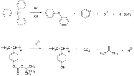

A positive photoresist is a type of photoresist in which a portion is exposed to light and becomes soluble to the photoresist developer. The unexposed portion of the photoresist remains insoluble in the photoresist developer.
Some examples of positive photoresists are:
PMMA (polymethylmethacrylate) single-component
- Resist for deep-UV, e-beam, x-ray
- Resin itself is DUV sensitive (slow)
- Chain scission mechanism
Two-component DQN resists:
- Common resists for mercury lamps
- Diazonaphthoquinone (DNQ) derivatives,[6] or Diazoquinone ester (DQ) 20-50% weight
- photosensitive
- hydrophobic, not water soluble
- Phenolic Novolak Resin (N)
- Frequently used for near-UV exposures
- Water soluble
- UV exposure destroys the inhibitory effect of DQ
- Issues: Adhesion, Etch Resistance
Negative photoresist
[edit]
A negative photoresist is a type of photoresist in which the portion of the photoresist that is exposed to light becomes insoluble in the photoresist developer. The unexposed portion of the photoresist is dissolved by the photoresist developer.
- Based on cyclized polyisoprene (rubber)
- variety of sensitizers (only a few % by weight)
- free radical initiated photo cross-linking of polymers
- Issues:
- potential oxygen inhibition
- swelling during development
- long narrow lines can become wavy
- swelling is an issue for high-resolution patterning
- Example: SU-8 (epoxy-based polymer), good adhesion), Kodak Photoresist (KPR)
Modulation transfer function
MTF (modulation transfer function is the ratio of image intensity modulation and object intensity modulation and it is a parameter that indicates the capability of an optical system.
Differences between positive and negative resist
[edit]The following table[7] is based on generalizations which are generally accepted in the microelectromechanical systems (MEMS) fabrication industry.
| Characteristic | Positive | Negative |
|---|---|---|
| Adhesion to silicon | Fair | Excellent |
| Relative cost | More expensive | Less expensive |
| Developer base | Aqueous | Organic |
| Solubility in the developer | Exposed region is soluble | Exposed region is insoluble |
| Minimum feature | 0.5 μm | 7 nm |
| Step coverage | Better | Lower |
| Wet chemical resistance | Fair | Excellent |
Classification
[edit]

Based on the chemical structure of photoresists, they can be classified into three types: photopolymeric, photodecomposing, and photocrosslinking photoresist.
- Photopolymeric photoresist is a type of photoresist, usually allyl monomer, which could generate free radical when exposed to light, then initiates the photopolymerization of monomer to produce a polymer. Photopolymeric photoresists are usually used for negative photoresist, e.g. methyl methacrylate and poly(phthalaldehyde)/PAG blends
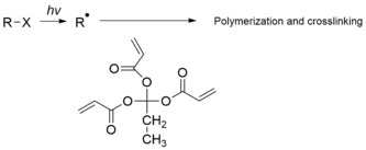
- Photocrosslinking photoresist is a type of photoresist, which could crosslink chain by chain when exposed to light, to generate an insoluble network. Photocrosslinking photoresist are usually used for negative photoresist.

- Photodecomposing photoresist is a type of photoresist that generates hydrophilic products under light. Photodecomposing photoresists are usually used for positive photoresist. A typical example is azide quinone, e.g. diazonaphthaquinone (DQ).
- For self-assembled monolayer (SAM) photoresist, first a SAM is formed on the substrate by self-assembly. Then, this surface covered by SAM is irradiated through a mask, similar to other photoresist, which generates a photo-patterned sample in the irradiated areas. And finally developer is used to remove the designed part (could be used as both positive or negative photoresist).[8]
Light sources
[edit]Absorption at UV and shorter wavelengths
[edit]In lithography, decreasing the wavelength of light source is the most efficient way to achieve higher resolution.[9] Photoresists are most commonly used at wavelengths in the ultraviolet spectrum or shorter (<400 nm). For example, diazonaphthoquinone (DNQ) absorbs strongly from approximately 300 nm to 450 nm. The absorption bands can be assigned to n-π* (S0–S1) and π-π* (S1–S2) transitions in the DNQ molecule.[citation needed] In the deep ultraviolet (DUV) spectrum, the π-π* electronic transition in benzene[10] or carbon double-bond chromophores appears at around 200 nm.[citation needed] Due to the appearance of more possible absorption transitions involving larger energy differences, the absorption tends to increase with shorter wavelength, or larger photon energy. Photons with energies exceeding the ionization potential of the photoresist (can be as low as 5 eV in condensed solutions)[11] can also release electrons which are capable of additional exposure of the photoresist. From about 5 eV to about 20 eV, photoionization of outer "valence band" electrons is the main absorption mechanism.[12] Above 20 eV, inner electron ionization and Auger transitions become more important. Photon absorption begins to decrease as the X-ray region is approached, as fewer Auger transitions between deep atomic levels are allowed for the higher photon energy. The absorbed energy can drive further reactions and ultimately dissipates as heat. This is associated with the outgassing and contamination from the photoresist.
Electron-beam exposure
[edit]Photoresists can also be exposed by electron beams, producing the same results as exposure by light. The main difference is that while photons are absorbed, depositing all their energy at once, electrons deposit their energy gradually, and scatter within the photoresist during this process. As with high-energy wavelengths, many transitions are excited by electron beams, and heating and outgassing are still a concern. The dissociation energy for a C-C bond is 3.6 eV. Secondary electrons generated by primary ionizing radiation have energies sufficient to dissociate this bond, causing scission. In addition, the low-energy electrons have a longer photoresist interaction time due to their lower speed; essentially the electron has to be at rest with respect to the molecule in order to react most strongly via dissociative electron attachment, where the electron comes to rest at the molecule, depositing all its kinetic energy.[13] The resulting scission breaks the original polymer into segments of lower molecular weight, which are more readily dissolved in a solvent, or else releases other chemical species (acids) which catalyze further scission reactions (see the discussion on chemically amplified resists below). It is not common to select photoresists for electron-beam exposure. Electron beam lithography usually relies on resists dedicated specifically to electron-beam exposure.
Parameters
[edit]Physical, chemical, and optical properties of photoresists influence their selection for different processes.[14] The primary properties of the photoresist are resolution capability, process dose and focus latitudes required for curing, and resistance to reactive ion etching.[15]: 966 [16] Other key properties are sensitivity, compatibility with tetramethylammonium hydroxide (TMAH), adhesion, environmental stability, and shelf life.[15]: 966 [16]
- Resolution
- Resolution is the ability to differ the neighboring features on the substrate. Critical dimension (CD) is a main measure of resolution. The smaller the CD is, the higher resolution would be.
- Contrast
- Contrast is the difference from exposed portion to unexposed portion. The higher the contrast is, the more obvious the difference between exposed and unexposed portions would be.
- Sensitivity
- Sensitivity is the minimum energy that is required to generate a well-defined feature in the photoresist on the substrate, measured in mJ/cm2. The sensitivity of a photoresist is important when using deep ultraviolet (DUV) or extreme-ultraviolet (EUV).
- Viscosity
- Viscosity is a measure of the internal friction of a fluid, affecting how easily it will flow. When it is needed to produce a thicker layer, a photoresist with higher viscosity will be preferred.
- Adherence
- Adherence is the adhesive strength between photoresist and substrate. If the resist comes off the substrate, some features will be missing or damaged.
- Etching resistance
- Anti-etching is the ability of a photoresist to resist the high temperature, different pH environment or the ion bombardment in the process of post-modification.
- Surface tension
- Surface tension is the tension that induced by a liquid tended to minimize its surface area, which is caused by the attraction of the particles in the surface layer. In order to better wet the surface of substrate, photoresists are required to possess relatively low surface tension.
Chemical amplification
[edit]Photoresists used in production for DUV and shorter wavelengths require the use of chemical amplification to increase the sensitivity to the exposure energy. This is done in order to combat the larger absorption at shorter wavelengths. Chemical amplification is also often used in electron-beam exposures to increase the sensitivity to the exposure dose. In the process, acids released by the exposure radiation diffuse during the post-exposure bake step. These acids render surrounding polymer soluble in developer. A single acid molecule can catalyze many such 'deprotection' reactions; hence, fewer photons or electrons are needed.[17] Acid diffusion is important not only to increase photoresist sensitivity and throughput, but also to limit line edge roughness due to shot noise statistics.[18] However, the acid diffusion length is itself a potential resolution limiter.[19] In addition, too much diffusion reduces chemical contrast, leading again to more roughness.[18]
The following reactions are an example of commercial chemically amplified photoresists in use today:
- photoacid generator + hν (193 nm) → acid cation + sulfonate anion [20]
- sulfonate anion + hν (193 nm) → e− + sulfonate[21]
- e− + photoacid generator → e− + acid cation + sulfonate anion [20]
The e− represents a solvated electron, or a freed electron that may react with other constituents of the solution. It typically travels a distance on the order of many nanometers before being contained;[22][23] such a large travel distance is consistent with the release of electrons through thick oxide in UV EPROM in response to ultraviolet light. This parasitic exposure would degrade the resolution of the photoresist; for 193 nm the optical resolution is the limiting factor anyway, but for electron beam lithography or EUVL it is the electron range that determines the resolution rather than the optics.
Types
[edit]One very common positive photoresist used with the I, G and H-lines from a mercury-vapor lamp is based on a mixture of diazonaphthoquinone (DNQ) and novolac resin (a phenol formaldehyde resin). DNQ inhibits the dissolution of the novolac resin, but upon exposure to light, the dissolution rate increases even beyond that of pure novolac. The mechanism by which unexposed DNQ inhibits novolac dissolution is not well understood, but is believed to be related to hydrogen bonding (or more exactly diazocoupling in the unexposed region). DNQ-novolac resists are developed by dissolution in a basic solution (usually 0.26N tetramethylammonium hydroxide (TMAH) in water).
Epoxy-based resists
[edit]One very common negative photoresist is based on epoxy-based oligomer. The common product name is SU-8 photoresist, and it was originally invented by IBM, but is now sold by Microchem and Gersteltec. One unique property of SU-8 is that it is very difficult to strip. As such, it is often used in applications where a permanent resist pattern (one that is not strippable, and can even be used in harsh temperature and pressure environments) is needed for a device.[24] Mechanism of epoxy-based polymer is shown in 1.2.3 SU-8. SU-8 is prone to swelling at smaller feature sizes, which has led to the development of small-molecule alternatives that are capable of obtaining higher resolutions than SU-8.[25]
Off-stoichiometry thiol-enes(OSTE) polymer
[edit]In 2016, OSTE Polymers were shown to possess a unique photolithography mechanism, based on diffusion-induced monomer depletion, which enables high photostructuring accuracy. The OSTE polymer material was originally invented at the KTH Royal Institute of Technology, but is now sold by Mercene Labs. Whereas the material has properties similar to those of SU8, OSTE has the specific advantage that it contains reactive surface molecules, which make this material attractive for microfluidic or biomedical applications.[14]
Hydrogen silsesquioxane (HSQ)
[edit]HSQ is a common negative resist for e-beam, but also useful for photolithography. Originally invented by Dow Corning (1970),[26] and now produced (2017) by Applied Quantum Materials Inc. (AQM). Unlike other negative resists, HSQ is inorganic and metal-free. Therefore, exposed HSQ provides a low dielectric constant (low-k) Si-rich oxide. A comparative study against other photoresists was reported in 2015 (Dow Corning HSQ).[27]
Applications
[edit]

Microcontact printing
[edit]Microcontact printing was described by Whitesides Group in 1993. Generally, in this techniques, an elastomeric stamp is used to generate two-dimensional patterns, through printing the “ink” molecules onto the surface of a solid substrate.[28]
Step 1 for microcontact printing. A scheme for the creation of a polydimethylsiloxane (PDMS) master stamp. Step 2 for microcontact printing A scheme of the inking and contact process of microprinting lithography.
Printed circuit boards
[edit]The manufacture of printed circuit boards is one of the most important uses of photoresist. Photolithography allows the complex wiring of an electronic system to be rapidly, economically, and accurately reproduced as if run off a printing press. The general process is applying photoresist, exposing image to ultraviolet rays, and then etching to remove the copper-clad substrate.[29]

Patterning and etching of substrates
[edit]This includes specialty photonics materials, MicroElectro-Mechanical Systems (MEMS), glass printed circuit boards, and other micropatterning tasks. Photoresist tends not to be etched by solutions with a pH greater than 3.[30]

Microelectronics
[edit]This application, mainly applied to silicon wafers and silicon integrated circuits is the most developed of the technologies and the most specialized in the field.[31]

See also
[edit]References
[edit]- ^ Eric, Anslyn; Dougherty, Dennis. Modern physical organic chemistry. University Science Books.
- ^ "Top Anti-reflective Coatings vs Bottom Anti-reflective Coatings".
- ^ MicroChemicals. "Basics of Microstructuring: Anti-Reflective Coatings" (PDF). Microchemicals GmbH. Retrieved 2020-01-31.
- ^ "AR™ 10L Bottom Anti-Reflectant Coating (BARC) | DuPont". dupont.com.
- ^ Ito, H.; Willson, C. G.; Frechet, J. H. J. (1982-09-01). "New UV Resists with Negative or Positive Tone". 1982 Symposium on VLSI Technology. Digest of Technical Papers: 86–87.
- ^ Reiser, A. (2002). "The molecular mechanism of novolak–diazonaphthoquinone resists". Review. European Polymer Journal. 38 (4): 619–629. doi:10.1016/S0014-3057(01)00230-0. Retrieved 2025-06-07.
- ^ Madou, Marc (2002-03-13). Fundamentals of Microfabrication. CRC Press. ISBN 978-0-8493-0826-0.
- ^ Huang, Jingyu; Dahlgren, David A.; Hemminger, John C. (1994-03-01). "Photopatterning of Self-Assembled Alkanethiolate Monolayers on Gold: A Simple Monolayer Photoresist Utilizing Aqueous Chemistry". Langmuir. 10 (3): 626–628. doi:10.1021/la00015a005. ISSN 0743-7463.
- ^ Bratton, Daniel; Yang, Da; Dai, Junyan; Ober, Christopher K. (2006-02-01). "Recent progress in high resolution lithography". Polymers for Advanced Technologies. 17 (2): 94–103. doi:10.1002/pat.662. ISSN 1099-1581. S2CID 55877239.
- ^ Ishii, Hiroyuki; Usui, Shinji; Douki, Katsuji; Kajita, Toru; Chawanya, Hitoshi; Shimokawa, Tsutomu (2000-01-01). Houlihan, Francis M (ed.). "Design and lithographic performances of 193-specific photoacid generators". Advances in Resist Technology and Processing XVII. 3999: 1120–1127. Bibcode:2000SPIE.3999.1120I. doi:10.1117/12.388276. S2CID 98281255.
- ^ Belbruno, Joseph (1990). "Multiphoton-induced chemistry of phenol in hexane at 266 nm". Chemical Physics Letters. 166 (2): 167–172. Bibcode:1990CPL...166..167B. doi:10.1016/0009-2614(90)87271-r.
- ^ Weingartner, Joseph C; Draine, B. T; Barr, David K (2006). "Photoelectric Emission from Dust Grains Exposed to Extreme Ultraviolet and X-Ray Radiation". The Astrophysical Journal. 645 (2): 1188–1197. arXiv:astro-ph/0601296. Bibcode:2006ApJ...645.1188W. doi:10.1086/504420. S2CID 13859981.
- ^ Braun, M; Gruber, F; Ruf, M. -W; Kumar, S. V. K; Illenberger, E; Hotop, H (2006). "IR photon enhanced dissociative electron attachment to SF6: Dependence on photon, vibrational, and electron energy". Chemical Physics. 329 (1–3): 148. Bibcode:2006CP....329..148B. doi:10.1016/j.chemphys.2006.07.005.
- ^ a b Greener, Jesse; Li, Wei; Ren, Judy; Voicu, Dan; Pakharenko, Viktoriya; Tang, Tian; Kumacheva, Eugenia (2010-02-02). "Rapid, cost-efficient fabrication of microfluidic reactors in thermoplastic polymers by combining photolithography and hot embossing". Lab Chip. 10 (4): 522–524. doi:10.1039/b918834g. ISSN 1473-0189. PMID 20126695. S2CID 24567881.
- ^ a b Physical properties of polymer handbook. James E. Mark (2 ed.). New York: Springer. 2006. ISBN 978-0-387-31235-4. OCLC 619279219.
{{cite book}}: CS1 maint: others (link) - ^ a b Lin, Qinghuang (2007), Mark, James E. (ed.), "Properties of Photoresist Polymers", Physical Properties of Polymers Handbook, New York, NY: Springer New York, pp. 965–979, doi:10.1007/978-0-387-69002-5_57, ISBN 978-0-387-31235-4, retrieved 2023-01-06
- ^ U.S. patent 4,491,628 "Positive and Negative Working Resist Compositions with Acid-Generating Photoinitiator and Polymer with Acid-Labile Groups Pendant From Polymer Backbone" J.M.J. Fréchet, H. Ito and C.G. Willson 1985.[1]
- ^ a b Van Steenwinckel, David; Lammers, Jeroen H.; Koehler, Thomas; Brainard, Robert L.; Trefonas, Peter (2006). "Resist effects at small pitches". Journal of Vacuum Science and Technology B. 24 (1): 316–320. Bibcode:2006JVSTB..24..316V. doi:10.1116/1.2151912.
- ^ Chochos, Ch.L.; Ismailova, E. (2009). "Hyperbranched Polymers for Photolithographic Applications – Towards Understanding the Relationship between Chemical Structure of Polymer Resin and Lithographic Performances". Advanced Materials. 21 (10–11): 1121. Bibcode:2009AdM....21.1121C. doi:10.1002/adma.200801715. S2CID 95710610.
- ^ a b S. Tagawa; et al. (2000). Houlihan, Francis M. (ed.). "Radiation and photochemistry of onium salt acid generators in chemically amplified resists". Proc. SPIE. Advances in Resist Technology and Processing XVII. 3999: 204. Bibcode:2000SPIE.3999..204T. doi:10.1117/12.388304. S2CID 95525894.
- ^ Wang, Xue-Bin; Ferris, Kim; Wang, Lai-Sheng (2000). "Photodetachment of Gaseous Multiply Charged Anions, Copper Phthalocyanine Tetrasulfonate Tetraanion: Tuning Molecular Electronic Energy Levels by Charging and Negative Electron Binding". The Journal of Physical Chemistry A. 104 (1): 25–33. Bibcode:2000JPCA..104...25W. doi:10.1021/jp9930090.
- ^ Lu, Hong; Long, Frederick H.; Eisenthal, K. B. (1990). "Femtosecond studies of electrons in liquids". Journal of the Optical Society of America B. 7 (8): 1511. Bibcode:1990JOSAB...7.1511L. doi:10.1364/JOSAB.7.001511.
- ^ Lukin, L; Balakin, Alexander A. (2001). "Thermalization of low energy electrons in liquid methylcyclohexane studied by the photoassisted ion pair separation technique". Chemical Physics. 265 (1): 87–104. Bibcode:2001CP....265...87L. doi:10.1016/S0301-0104(01)00260-9.
- ^ DeForest, William S (1975). Photoresist: materials and processes. McGraw-Hill Companies.
- ^ Lawson, Richard; Tolbert, Laren; Younkin, Todd; Henderson, Cliff (2009). Henderson, Clifford L (ed.). "Negative-tone molecular resists based on cationic polymerization". Proc. SPIE 7273, Advances in Resist Materials and Processing Technology. Advances in Resist Materials and Processing Technology XXVI. XXVI: 72733E. Bibcode:2009SPIE.7273E..3EL. doi:10.1117/12.814455. S2CID 122244702.
- ^ Frye, Cecil L.; Collins, Ward T. (1970-09-01). "Oligomeric silsesquioxanes, (HSiO3/2)n". Journal of the American Chemical Society. 92 (19): 5586–5588. Bibcode:1970JAChS..92.5586F. doi:10.1021/ja00722a009. ISSN 0002-7863.
- ^ Mojarad, Nassir; Gobrecht, Jens; Ekinci, Yasin (2015-03-18). "Beyond EUV lithography: a comparative study of efficient photoresists' performance". Scientific Reports. 5 (1): 9235. Bibcode:2015NatSR...5.9235M. doi:10.1038/srep09235. ISSN 2045-2322. PMC 4363827. PMID 25783209.
- ^ "Self-assembled Monolayer Films: Microcontact Printing" (PDF).
- ^ Montrose, Mark I (1999). The Electronic Packaging Handbook. CRC Press.
- ^ Novak, R.E (2000). Cleaning Technology in Semiconductor Device Manufacturing. Electrochemical Society Inc. ISBN 978-1566772594.
- ^ Silicon photonics. Springer Science & Business Media. 2004.
Photoresist
View on GrokipediaIntroduction
Definition and Principles
Photoresist is a light-sensitive material, typically a polymer-based formulation, that undergoes a chemical transformation when exposed to radiation such as ultraviolet light, enabling the creation of microscopic patterns on substrates during microfabrication processes.[7] These materials are essential in semiconductor manufacturing, where they facilitate the precise patterning of integrated circuits and other microelectronic devices by allowing selective removal or retention of material layers.[8] In essence, photoresist serves as a temporary mask that transfers geometric patterns from a photomask to the underlying substrate, forming the basis for subsequent etching or deposition steps in device fabrication.[9] The core principle of photoresist operation lies in the radiation-induced change in its solubility within a developer solvent, which allows for the selective dissolution of exposed or unexposed regions to reveal the desired pattern.[8] This solubility modulation is achieved through photolithography techniques, including contact printing (direct mask-substrate contact), proximity printing (small gap between mask and substrate), or projection printing (using optics to image the mask onto the resist-coated wafer).[7] The process begins with substrate preparation, such as cleaning to remove contaminants and applying an adhesion promoter to ensure uniform coating.[9] Photoresist is then applied via spin coating, where the liquid formulation is dispensed onto the rotating substrate to form a thin, uniform film, followed by a soft bake to evaporate solvents and improve adhesion.[8] Exposure to radiation through the photomask alters the resist's properties, often followed by a post-exposure bake to amplify the chemical changes. Development then removes the soluble portions, a hard bake stabilizes the remaining pattern, and finally, pattern transfer occurs via etching or deposition before resist stripping.[7] At the chemical level, photoresists typically comprise a resin (the structural polymer), a solvent for application, and photosensitive components such as photoinitiators or photoactive compounds (PACs) that absorb radiation and initiate reactions.[8] Upon photon absorption, these groups trigger molecular changes, including polymerization (chain growth), depolymerization (chain breaking), or cross-linking (intermolecular bonding), which alter the resin's solubility characteristics.[9] In chemically amplified resists, a common variant, photoacid generators produce catalytic acids during exposure that diffuse during baking to enhance the reaction efficiency, enabling high-resolution patterning at lower doses.[7] This foundational chemistry ensures the fidelity of pattern transfer in microfabrication, where even minor variations can impact device performance.[8]Historical Development
The foundations of photoresist technology trace back to the 19th century, when early experiments with light-sensitive materials laid the groundwork for photosensitive compounds. Practical applications emerged in the 1940s, when researchers at Kalle Chemical Works in Germany developed the first DNQ-novolac positive photoresist for offset printing plates, marking the transition from rudimentary light-sensitive coatings to structured imaging materials. This innovation, initially used in blueprinting and reprography, provided high resolution and stability, setting the stage for broader industrial adoption.[10][11] In the 1950s and 1960s, photoresists entered the burgeoning semiconductor industry, driven by the need for precise patterning in integrated circuit (IC) fabrication. Kodak introduced KTFR (Kodak Thin Film Resist) in 1957, a negative-tone resist based on cyclized polyisoprene, which became the first commercially viable material for microlithography and enabled early transistor production.[12][13] By the mid-1960s, positive-tone resists gained prominence; Kodak's KPR in 1965 offered improved resolution without swelling during development, while Shipley Company developed the AZ series, including AZ-1350 in 1965, optimized for semiconductor processing with novolac resins and DNQ sensitizers.[14][15][16] These materials supported the shift from manual etching to photolithographic techniques, facilitating the scaling of IC features from tens of microns to sub-10-micron nodes. The 1970s and 1980s saw a pivot toward positive resists for finer features, culminating in the invention of chemically amplified photoresists (CARs) to meet the demands of deep ultraviolet (DUV) lithography. Novolac-DNQ systems dominated early IC production but struggled with shorter wavelengths due to high absorbance; this led to the development of more transparent polymers. In 1982, IBM researchers Hiroshi Ito, C. Grant Willson, and Jean M. J. Fréchet proposed the chemical amplification mechanism, using photoacid generators (PAGs) to catalytically deprotect polymers like poly(t-butyloxycarbonyloxystyrene) (t-BOC), dramatically increasing sensitivity for 248 nm KrF excimer lasers. Patented as US 4,491,628, this breakthrough enabled sub-micron patterning and was first implemented in 1 Mb DRAM production by 1986, reducing exposure doses by orders of magnitude.[17][18][19] From the 1990s to the 2000s, photoresist evolution aligned with advancing lithography nodes, incorporating DUV at 193 nm (ArF) and laying groundwork for extreme ultraviolet (EUV). CARs based on methacrylates and PAGs became standard, supporting immersion lithography and enabling features below 100 nm; key innovations included hybrid resists with silicon for etch resistance. EUV development accelerated in the late 1990s through consortia like EUV LLC, focusing on low-outgassing materials for 13.5 nm wavelengths, though commercial adoption lagged until the 2010s. By the mid-2000s, resists like those from Dow and JSR facilitated 45 nm nodes, sustaining Moore's Law amid challenges like line-edge roughness.[20][21][22] In the 2010s to 2025, photoresists advanced toward EUV compatibility and sustainability, with metal-oxide resists (MORs) emerging to address absorption and resolution limits at sub-10 nm scales. Inpria Corporation, spun out from Oregon State University in 2007, pioneered inorganic MORs using hafnium or zirconium oxides, offering high EUV absorption and etch resistance for high-NA EUV systems. Lam Research introduced Aether dry photoresist in 2020, a solvent-free MOR that boosted productivity by eliminating wet development, and by 2025, it was adopted for advanced DRAM production. Collaborations, such as the 2025 cross-licensing between Lam, JSR, and Inpria, accelerated MOR integration for 2 nm nodes. Environmental pressures, including EU REACH regulations and PFAS phase-outs post-2015, drove shifts to low-toxicity alternatives, replacing perfluorooctanoic acid (PFOA) surfactants with polymeric options to minimize bioaccumulation. These innovations have been pivotal in enabling Moore's Law progression to sub-2 nm features by 2025, supporting 3D NAND, AI chips, and high-performance computing.[23][24][25][26][27]Photoresist Polarity and Basic Mechanisms
Positive Photoresists
Positive photoresists are materials in which the regions exposed to light become more soluble in a developer solution, allowing for the selective removal of irradiated areas during the patterning process. This solubility change is primarily driven by the photochemical cleavage of photosensitive groups within the resist formulation, typically consisting of a photoactive compound (PAC) such as diazonaphthoquinone (DNQ) dissolved in a novolac resin matrix. Upon exposure to ultraviolet (UV) light, the DNQ undergoes a photolytic reaction that transforms it into a soluble product, enabling high-fidelity pattern transfer in lithographic applications.[28] The core mechanism involves the absorption of photons by the DNQ, which triggers a Wolff rearrangement, leading to the formation of a ketene intermediate that reacts with water to produce indene carboxylic acid and nitrogen gas. This carboxylic acid is highly polar and ionizable, dramatically increasing the solubility of the exposed resist in aqueous alkaline developers like tetramethylammonium hydroxide (TMAH). The simplified chemical reaction can be represented as: In unexposed areas, the intact DNQ acts as a dissolution inhibitor for the novolac resin, maintaining low solubility and preserving the resist structure.[28][29] A key process step in positive photoresist lithography is the post-exposure bake (PEB), which enhances the uniformity of the solubility contrast. The performance of these resists is often characterized by their contrast curve, where the gamma value (γ) quantifies the steepness of the solubility transition; values greater than 1 indicate a sharp change from insoluble to soluble states, enabling precise control over feature dimensions.[30] Positive photoresists offer advantages such as superior resolution for fine patterns and improved process control due to high dissolution contrast.[31][32] However, they have limitations including sensitivity to airborne molecular contamination that can degrade pattern fidelity during post-exposure delay.[33] An archetypal example is the use of DNQ-novolac positive resists in i-line (365 nm) lithography, where they provide reliable patterning for micron-scale features in integrated circuit fabrication.[28] Unlike negative photoresists, positive variants produce patterns matching the mask transparency, which can simplify certain alignment processes.[31]Negative Photoresists
Negative photoresists function by rendering exposed regions insoluble in the developer through light-induced chemical changes, primarily free-radical polymerization or cross-linking within the polymer matrix.[34] Upon exposure to ultraviolet light, photoinitiators generate free radicals that propagate chain reactions, linking polymer molecules and increasing molecular weight to prevent dissolution in organic solvents.[35] This mechanism contrasts with positive photoresists by inverting the pattern, where unexposed areas are removed, often trading off some resolution for structural robustness.[36] A representative chemical reaction in bis-azide sensitized systems involves photodecomposition of the sensitizer: The reactive nitrenes (:N) then insert into C-H bonds of the host polymer, such as cyclized rubber or novolac resin, forming a stable cross-linked network that insolubilizes the exposed area.[37] This cross-linking enhances the resist's resistance to subsequent etching or plating processes. Key advantages of negative photoresists include the capability to form thicker films, often exceeding 100 μm, owing to the mechanical stability imparted by extensive cross-linking; improved adhesion to substrates like silicon or metals; and their suitability for fabricating high-aspect-ratio microstructures in microelectromechanical systems (MEMS).[36] These properties make them ideal for applications requiring durable, three-dimensional features, such as microfluidic channels or sensors. Despite these benefits, negative photoresists have notable limitations, including swelling of cross-linked regions during development in organic solvents, which distorts features and reduces resolution through phenomena like undercut (lateral dissolution beyond the exposed edge) or scumming (residue in unexposed areas). They also typically exhibit lower contrast, limiting their effectiveness for sub-micron features where precise sidewall control is critical.[36] Process considerations for negative photoresists center on mitigating oxygen inhibition in free-radical mechanisms, as atmospheric oxygen reacts with initiating radicals to suppress polymerization and cause surface tackiness or incomplete curing; exposures are thus performed under inert atmospheres like nitrogen to ensure uniform results.[38] The sensitivity curve illustrates this dynamic: below a threshold dose (e.g., ~50-200 mJ/cm² depending on formulation), the resist remains fully soluble, but exceeding this point triggers rapid insolubilization as cross-link density rises, often reaching near-complete resistance after a factor of 2-5 times the threshold.[36] Historical examples include early rubber-based negative photoresists, such as Kodak's KTFR (1957), which combined cyclized poly(cis-isoprene) with bis-azide sensitizers for the first mass-produced microlithography applications.[39] In contemporary use, negative photoresists enable thick-film processing up to 100 μm, as seen in epoxy formulations for MEMS structures like accelerometers or gears, where high fidelity and etch resistance are paramount.Classification and Performance Parameters
Classification Schemes
Photoresists are categorized through various schemes that reflect their chemical composition, response to exposure, intended use, and adaptation to technological advancements. These classifications provide a structured framework for selecting materials in photolithography processes, enabling engineers to match resists to specific fabrication requirements such as resolution, contrast, and environmental compatibility.[40] One primary classification distinguishes photoresists by polarity, dividing them into positive and negative types. Positive photoresists become more soluble in exposed areas, allowing the irradiated regions to be removed during development, while negative photoresists become less soluble or insoluble in exposed areas, retaining those regions after development. This fundamental dichotomy influences pattern inversion and is foundational for most lithographic applications.[41] Photoresists are also classified by their chemical composition, primarily as organic or inorganic. Organic photoresists, typically polymer-based, dominate conventional applications due to their ease of processing and compatibility with standard solvents, offering good adhesion and flexibility. Inorganic photoresists, such as those based on metal oxides like hafnium or zirconium, provide enhanced etch resistance and are increasingly used in high-resolution scenarios, though they often require specialized deposition methods. Within organic types, a further distinction exists between conventional and chemically amplified photoresists; conventional resists rely on direct photochemical reactions for solubility changes, whereas chemically amplified resists employ photoacid generators to catalyze chain reactions, improving sensitivity for shorter wavelengths.[40][17] Classification by exposure wavelength or energy source addresses the evolution of lithography tools, tailoring resists to specific spectral sensitivities. Traditional near-ultraviolet resists include g-line (436 nm) and i-line (365 nm) types, suited for older stepper systems with resolutions around 0.5–1 μm. Deep ultraviolet (DUV) resists operate at 248 nm (KrF excimer) or 193 nm (ArF excimer), enabling sub-100 nm features critical for advanced nodes. Extreme ultraviolet (EUV) resists target 13.5 nm wavelengths for patterns below 7 nm, often incorporating metal-organic components for higher absorption. Electron-beam (e-beam) resists, used in mask writing or direct-write lithography, respond to high-energy electrons rather than photons, prioritizing high resolution over throughput.[42] Another scheme categorizes photoresists by tone, particularly monotone versus dual-tone. Monotone resists exhibit a single solubility behavior post-exposure, either positive or negative. Dual-tone resists, however, can switch tone based on developer choice or processing conditions, allowing positive or negative patterns from the same material, which aids in inspection and alignment verification by changing color post-exposure.[43] By application, photoresists are divided into imaging (thin-film) and structural (thick-film) types. Imaging photoresists, typically 0.5–2 μm thick, focus on high-resolution pattern transfer in semiconductor fabrication. Structural photoresists, often exceeding 50 μm in thickness, support electroplating or molding in microelectromechanical systems (MEMS), providing mechanical stability for high-aspect-ratio structures. Emerging classification schemes emphasize sustainability and performance for nanoscale fabrication. Eco-friendly photoresists prioritize low volatile organic compound (VOC) formulations to minimize environmental impact, using water-based or bio-derived solvents while maintaining lithographic efficacy. High-resolution schemes target 5 nm nodes, favoring EUV-compatible materials with low line-edge roughness. Post-2020 developments highlight hybrid organic-inorganic classifications, blending polymer matrices with inorganic nanoparticles for improved EUV absorption, etch selectivity, and reduced outgassing. Recent innovations include dry photoresists, deposited via vapor-phase methods to eliminate solvents, improving environmental compatibility and enabling resolutions like 28 nm pitch in high-NA EUV lithography as of 2025.[44][45][46]Key Parameters and Evaluation Metrics
The performance of photoresists is characterized by several key parameters that determine their suitability for lithographic processes, including resolution, sensitivity, contrast, adhesion, etch resistance, thermal stability, and line edge roughness (LER). These metrics are evaluated through standardized testing to ensure reliability in semiconductor manufacturing and other applications. Resolution and critical dimension (CD) refer to the minimum feature size achievable, limited by the Rayleigh criterion expressed as , where is a process-dependent factor typically ranging from 0.25 to 1, is the exposure wavelength, and is the numerical aperture of the optical system.[47] This limit is measured using scanning electron microscopy (SEM) to assess patterned features after development.[47] Sensitivity quantifies the exposure dose required to induce a significant change in the photoresist's solubility, typically defined as the dose in mJ/cm² for a 50% solubility change or, for positive resists, the dose-to-clear (D₀), which is the minimum dose to fully dissolve the exposed area during development.[36] Lower doses indicate higher sensitivity, enabling faster processing but potentially compromising other properties like contrast. Contrast (γ) measures the steepness of the transition in the solubility versus log-dose curve, calculated as , where is the dose at which the resist begins to dissolve and is the dose for full dissolution (remaining thickness from ~100% to 0%).[48] Higher γ values (>2–3) signify sharper pattern definition and reduced dose latitude. Adhesion evaluates the photoresist's bonding to the substrate, often tested via peel or tape tests to quantify detachment force, while etch resistance assesses durability during plasma etching, measured by etch rates in gases like CF₄/O₂, where rates below 100 nm/min are desirable for masking layers.[49] Thermal stability is gauged by the glass transition temperature (T_g), typically exceeding 150°C to withstand post-exposure bakes without deformation, and low outgassing rates under vacuum to prevent contamination in processes like EUV lithography.[50][51] Line edge roughness (LER) describes edge deviations, with standard deviation σ targeted below 3 nm for EUV applications to minimize CD variability; it is measured using critical dimension SEM (CD-SEM).[52] Testing adheres to SEMI guidelines, such as those for thin-film uniformity (e.g., site distribution patterns for thickness variation <5% across wafers) and defectivity (e.g., particle counts and pattern anomalies via inspection tools).[53] These standards ensure consistent evaluation, focusing on metrics like dose uniformity and defect density to support high-volume manufacturing.Exposure Techniques
Optical Exposure Methods
Optical exposure methods in photolithography rely on controlled illumination to transfer patterns into photoresists, primarily using ultraviolet and shorter wavelengths to achieve high resolution. High-pressure mercury arc lamps serve as broadband ultraviolet sources, emitting prominent spectral lines such as g-line at 436 nm, h-line at 405 nm, and i-line at 365 nm, which have historically enabled feature sizes down to approximately 220 nm in early semiconductor processes.[54] For advanced deep ultraviolet (DUV) applications, excimer lasers provide monochromatic output, with KrF lasers operating at 248 nm to support features around 80 nm, and ArF lasers at 193 nm enabling resolutions as small as 38 nm through projection optics.[54] Extreme ultraviolet (EUV) systems utilize laser-produced plasma sources, typically generated by pulsing high-power lasers on tin droplets to produce light at 13.5 nm, while earlier developments incorporated synchrotron radiation for similar wavelengths; these sources facilitate sub-10 nm patterning in vacuum environments to mitigate atmospheric absorption.[54] Light absorption within the photoresist film governs the exposure depth and uniformity, following the Beer-Lambert law:where represents absorbance, is the molar absorptivity of the photosensitive component, its concentration, and the film thickness.[55] This exponential attenuation necessitates designs that promote transparency in thicker films, often achieved through photosensitizer bleaching during exposure, which reduces absorption coefficients from initial values of 1-2 μm⁻¹ to allow deeper light penetration and more uniform reaction throughout the resist volume.[36] Shorter exposure wavelengths fundamentally enhance resolution by reducing the minimum resolvable feature size, as dictated by the Rayleigh criterion:
where is the critical dimension, the wavelength, the numerical aperture, and a process-dependent factor approaching a physical limit of 0.25.[56] Progressing to wavelengths below 200 nm, such as in DUV and EUV, enables sub-50 nm features but introduces challenges including heightened material absorption and environmental interactions, exemplified by oxygen quenching that can degrade photon efficiency and necessitate inert atmospheres or vacuum operation.[36] To push beyond single-exposure limits, process enhancements like immersion lithography fill the gap between the projection lens and wafer with purified water, exploiting its refractive index of 1.44 at 193 nm to elevate NA values up to 1.35 and effectively shorten the perceived wavelength for improved resolution.[57] For sub-10 nm regimes, multiple patterning techniques—such as litho-etch-litho-etch (LELE) or self-aligned double patterning—divide complex patterns into sequential exposures, synergizing with DUV or EUV to achieve half-pitches below 20 nm while managing overlay precision.[58] Recent advances in EUV adoption, particularly by 2025, have accelerated with ASML's high-volume manufacturing tools like the NXE:3600 series supporting 3 nm and below nodes, driven by demand in AI and memory chips.[59] In photon-limited EUV regimes, where low flux leads to stochastic noise manifesting as line-edge roughness or defects, mitigation strategies include dose increases and photoresist formulations that enhance secondary electron yields, reducing variability in acid generation and pattern fidelity.[60]
Non-Optical Exposure Methods
Electron-beam lithography (EBL) utilizes a finely focused beam of electrons, typically accelerated to energies between 1 and 100 keV, to directly pattern photoresists without a physical mask. The primary mechanism involves the penetration of primary electrons into the resist, causing ionization and generating secondary electrons that induce chemical changes, such as the formation of radicals or acids, which alter the resist's solubility for subsequent development.[3][61] This electron-mediated energy deposition provides higher sensitivity than traditional UV exposure, often requiring doses on the order of 100-1000 μC/cm² for common resists, though the process remains inherently serial, scanning patterns point by point.[62] Energy absorption in EBL parallels optical methods but occurs via electron scattering rather than photon absorption, enabling precise control over localized reactions.[63] A key challenge in EBL is the proximity effect, arising from forward scattering within the resist (limited to ~10-50 nm) and backscattering from the substrate (extending tens of micrometers), which causes overexposure in dense pattern areas and underexposure in isolated features. This is mitigated through dose modulation, where the electron dose is computationally adjusted—higher in isolated regions and lower in dense ones—based on models like double Gaussian distributions to achieve uniform exposure.[64][65] EBL offers sub-1 nm resolution, maskless flexibility for custom designs, and is widely used for photomask fabrication in microelectronics prototyping and research.[66] However, limitations include low throughput (often hours per wafer due to serial scanning), substrate charging on insulators that deflects the beam, and the need for high-vacuum environments to prevent electron scattering by air molecules.[67][68] Ion-beam lithography, particularly helium ion beam (HIB) systems, provides an alternative for ultra-high-resolution patterning, achieving features below 5 nm with reduced proximity effects compared to EBL. In HIB, ions interact over a shorter range (~10-20 nm) than electrons, generating fewer secondary electrons and enabling sharp profiles in resists without extensive correction; resolutions as fine as 4 nm have been demonstrated on high-sensitivity resists like HSQ.[69][70] These systems operate in vacuum and are maskless, supporting direct-write applications, though they share EBL's throughput constraints for large areas. X-ray lithography employs collimated soft X-rays (0.4-4 nm wavelength) from synchrotron sources to expose photoresists, excelling in patterning thick layers up to hundreds of micrometers for applications like the LIGA process in micromechanics. The high penetration of X-rays ensures uniform exposure through dense resists like PMMA or SU-8, minimizing diffraction and scattering effects that limit optical methods, while achieving resolutions below 100 nm.[71][72] Synchrotron-based systems provide intense flux for efficient processing, but require specialized masks and vacuum setups, with limited adoption due to source availability.[73] Advancements in non-optical methods include multi-beam EBL systems, such as those developed by IMS Nanofabrication, which parallelize thousands of beams (e.g., 262,000 in the MBMW-101) to boost throughput by up to 100 times over single-beam tools, enabling production-scale mask writing for 7 nm nodes and beyond.[74] By 2025, these technologies support growing demands in advanced semiconductor R&D and prototyping, with market projections indicating sustained expansion.[75]Chemically Amplified and Advanced Photoresists
Chemical Amplification Mechanisms
Chemically amplified resists (CARs) were invented in the mid-1980s at IBM Research by Hiroshi Ito, C. Grant Willson, and Jean M. J. Fréchet to address the need for higher sensitivity in deep ultraviolet lithography, enabling the production of advanced integrated circuits such as 1 Mb DRAMs. The core principle of chemical amplification relies on a single photon generating an acid catalyst via a photoacid generator (PAG), which then diffuses during post-exposure bake (PEB) to trigger a cascade of reactions, amplifying the effect far beyond the initial exposure site and enhancing overall resist sensitivity. This diffusion typically occurs over an acid diffusion length of approximately 10-20 nm, allowing the catalyst to influence unexposed regions nearby while maintaining pattern fidelity. The mechanism begins with the photolysis of the PAG upon exposure to light (hν), producing a proton (H⁺) and a counter anion:PAG + hν → H⁺ + An⁻.
This acid then catalyzes deprotection reactions in the polymer during PEB. For example, in positive-tone CARs, the acid promotes the removal of a tert-butoxycarbonyl (t-BOC) protecting group:
Polymer-O-C(O)-O-C(CH₃)₃ + H⁺ → Polymer-OH + (CH₃)₂C=CH₂ + CO₂,
rendering the polymer soluble in aqueous base developer.[76] The rate of deprotection can be modeled as d[M]/dt = -k_amp [H⁺][M], where [M] is the concentration of protected sites, k_amp is the amplification rate constant, and [H⁺] is the acid concentration, highlighting the catalytic nature of the process.[76] CARs are classified into binary and ternary systems. Binary CARs consist of a polymer matrix and PAG, where the acid directly catalyzes the reaction without additional additives. Ternary CARs incorporate basic quenchers, such as amines or photo decomposable quenchers (PDQ), alongside the polymer and PAG to neutralize excess acid and control diffusion, improving contrast and reducing unwanted reactions. PDQ neutralizes acid in unexposed areas as a base-like quencher but decomposes in exposed areas to lose its quenching effect, enhancing contrast; it utilizes an onium cation similar to PAGs but paired with a photo-labile anion (e.g., carboxylate or carbonate) for decomposition efficiency and unexposed stability.[77] In contrast to non-CARs, which rely on direct photochemical bond breaking with lower quantum efficiency, CARs achieve exponential amplification, where the factor is approximately the ratio of the acid diffusion volume to the photon absorption volume, often yielding 100- to 1000-fold sensitivity gains per photon.[17] The primary advantages of CARs include dramatically improved sensitivity, such as below 10 mJ/cm² for extreme ultraviolet (EUV) lithography at 13.5 nm, enabling high-throughput patterning at advanced nodes.[78] This amplification also facilitated the adoption of 193 nm immersion lithography by providing the necessary speed and resolution for sub-100 nm features without excessive exposure doses. However, challenges arise from acid diffusion, which can cause line slimming and blur patterns, limiting resolution to scales comparable to the diffusion length. Additionally, airborne basic contaminants can poison the acid catalyst, reducing sensitivity, while delays between exposure and PEB lead to instability such as T-topping due to acid evaporation or neutralization. These issues are mitigated through environmental controls and optimized formulations, but remain critical for sub-10 nm nodes.