Hubbry Logo
Pin insulatorPin insulatorMain
Open search
Pin insulator
Community hub
Pin insulator
logo
8 pages, 0 posts
0 subscribers
Be the first to start a discussion here.
Pin insulator
Pin insulator
from Wikipedia
An insulator of a telephone transmission line
A pin insulator ceramic plate used for 20 KV lines

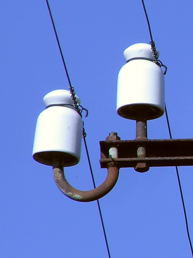
A pin insulator is a device that isolates a wire from a physical support such as a pin (a wooden or metal dowel of about 3 cm diameter with screw threads) on a telegraph or utility pole. It is a formed, single layer shape that is made out of a non-conducting material, usually porcelain or glass. It is thought to be the earliest developed overhead insulator and is still popularly used in power networks up to 33 KV. Single or multiple pin insulators can be used on one physical support, however, the number of insulators used depends upon the application's voltage.[1]

Pin insulators are one of three types of overhead insulators, the others being strain insulators and suspension insulators. Unlike the others, pin insulators are directly connected to the physical support compared to being suspended from the wire. Pin insulators are shaped to allow the secure attachment of the conducting wire and avoid it coming adrift. The wire is usually attached to the insulator by being wrapped around it or in other circumstances, fixed into grooves on the insulator itself.[2]

When an insulator is wet, its outer surface becomes conductive making the insulator less effective. An insulator has an umbrella-like design so that it can protect the lower part of the insulator from rain. To keep the inner side of the insulator dry, ridges around the insulator, "rain sheds", are made. These increase the creepage distance from the energized wire to the mounting pin. [3]

Collecting

[edit]

Pin insulators have become collectible items. All glass pin insulators are assigned a Consolidated Design (CD) number, a system first implemented by hobbyist N.R. Woodward in 1954, and widely introduced starting in 1965 by collector Helmer Turner. CD numbers first appeared in print in Woodward’s “Glass insulators in America, 1967 report”. Each CD number corresponds to a specific glass style, shape, or manufacturer. CD numbers are only hobby-specific for collectors, and are not used or recognised by insulator manufacturers.[4]

Insulators, at the time of manufacturing, were simply viewed as an engineering product and were not meant to be an entertainment product for spectators. This meant that the quality of the insulators was not a primary concern of the manufacturers that made them.[5] The finished product was usually discoloured from impurities and foreign objects diffused within the molten glass and metal molds. These impurities give the insulator a unique character and high value as collectors would rather obtain an imperfect product rather than a perfect, common product. Impurities in the glass can create amber swirls, milk swirls, graphite inclusions, and two or three-tone insulators. Foreign objects contained within the glass are known to be nails, pennies, and screws.[6]

Although glass insulators are the most popular for the majority of collectors, many people collect porcelain insulators as well. These also come in a variety of shapes, sizes, and colors. They are classified in the U and M systems, primarily developed by Jack Tod and Elton Gish. [7]

Manufacturers

[edit]
A sparkling CD 145 or "beehive" insulator from the telegraph era made by the Brookfield Glass Company circa 1882.
The same snowy CREB 145 sitting on its side

One of the major U.S. manufacturers that produced glass insulators during the 19th century and early 20th century in the USA was Brookfield Glass Company. It can be assumed that Brookfield may have had poor quality control as their insulators seem to be found with the most imperfections, however, this could be disputed.

Another major U.S. manufacturer that produced glass insulators was the Hemingray Glass Company. They were known for producing the most variety of colors. Some examples of colors that the company produced are yellow, golden yellow, butterscotch, glowing orange, amber, whiskey amber, "root beer" amber, orange-amber, red-amber, oxblood, green, lime green, sage green, depression green, emerald green, olive green, yellow-olive green, aqua, cornflower blue, electric blue, cobalt blue, sapphire blue, glowing peacock blue, and many others. Different colors were produced to allow two or more different utility companies to quickly identify which wires were theirs by the color of insulator if multiple wires were strung over the same utility pole. For example, one company may have a string of amber insulators, while another, on the same poles, might have their insulators in cobalt blue.

There are many manufacturers in the United States, Canada, and other countries that can be found embossed on all styles of insulators. A non-comprehensive list of these manufacturers is below:

United States

[edit]
  • AT&T
  • American Insulator Company
  • Armstrong
  • Brookfield Glass Company
  • Beaver Falls Glass Company
  • Baltimore glass manufacturing company
  • Barclay
  • Birmingham
  • Boston bottle works
  • Buzby
  • California
  • California Electric Works
  • Chambers
  • Chester
  • Chicago Insulating Company
  • Duquesne
  • Electrical Construction and Maintenance Company
  • Emminger’s
  • Gayner
  • Greeley
  • Gregory
  • Good
  • Hawley
  • Homer Brooks
  • Hamilton
  • Hemingray Glass Company
  • King City Glass Works (K.C.G.W.)
  • Kerr
  • Knowles
  • Kimble
  • Luther G. Tillotson & Company
  • Lefferts
  • Locke
  • Lynchburg
  • McLaughlin
  • Maydwell
  • McKee & Co.
  • McMicking
  • Mulford & Biddle
  • New England Glass Manufacturing Company (N.E.G.M.Co.)
  • National Insulator Company
  • Oakman Manufacturing Company
  • Ohio Valley Glass Company (O.V.G.Co.)
  • Owens Illinois
  • Paisley
  • Pyrex
  • Sterling
  • Seiler’s
  • Standard Glass Insulator Company
  • Thomas-Houston Electric Company
  • Thames Glass Works
  • Twiggs
  • Victor Insulators
  • Western Electric Manufacturing Company
  • Western Glass Manufacturing Company
  • Western Flint Glass Company
  • Whitall Tatum Company

Canada

[edit]
  • Diamond
  • Dominion
  • Hamilton Glass Works
  • G.N.W.TEL. Co.

International

[edit]


References

[edit]
[edit]
Revisions and contributorsEdit on WikipediaRead on Wikipedia
from Grokipedia
A pin insulator is a type of electrical insulator designed to support and electrically isolate overhead power line conductors from their supporting structures, such as utility poles or towers, preventing unwanted current flow while withstanding mechanical and environmental stresses. Typically constructed from porcelain, glass, or polymeric composite materials, it features a central threaded hole that allows it to be securely mounted on a galvanized steel or iron pin fixed to a cross-arm, with the conductor attached via a groove or tie wire at the top. These insulators originated in the mid-19th century for telegraph lines and evolved for power transmission; they are primarily used in medium-voltage distribution systems up to 33 kV, with multi-piece designs extending to higher voltages up to about 66 kV, offering reliability and cost-effectiveness for low- to medium-tension overhead lines. Despite limitations at very high voltages, pin insulators remain widely used globally in such systems.

Fundamentals

Definition and Function

A pin insulator is a non-conductive device designed to support and electrically isolate overhead conductors from grounded structures, such as utility poles or cross-arms, in electrical transmission and distribution systems. It serves as one of the three primary types of overhead insulators, alongside suspension and strain insulators. The primary function of a pin insulator is to provide robust mechanical support for conductors while preventing electrical current leakage to the ground or supporting structures, thereby ensuring safe and reliable power delivery. These insulators are typically employed in systems operating at voltages up to 33 kV, where they must withstand both tensile forces from the conductors and the stresses of environmental exposure without compromising insulation integrity. Key components of a pin insulator include a central pin hole at the base for secure mounting onto a galvanized bolt or pin fixed to the cross-arm, an umbrella-shaped that enhances the creepage distance for better insulation, and a tie-wire groove at the top for attaching the conductor via tie wires. This design allows the insulator to rigidly hold the conductor in position while distributing mechanical loads evenly. In its basic electrical role, the pin insulator maintains high to resist voltage stress, preventing or puncture under normal operating conditions and mitigating the effects of environmental factors such as and , which could otherwise reduce insulation effectiveness. The umbrella skirt, in particular, sheds rainwater to minimize surface conductivity, ensuring consistent performance in adverse weather.

Operating Principles

Pin insulators function through their dielectric properties, which enable them to isolate high-voltage conductors from grounded supports by resisting electrical conduction. These insulators exhibit high volume resistivity, typically exceeding 10^{12} ohm-cm and reaching up to 10^{14} ohm-cm for materials like at , ensuring minimal leakage current under normal operating conditions. Additionally, the , or per unit thickness, is approximately 60 kV/cm for , allowing the insulator to endure substantial without internal conduction or puncture. This combination of high resistivity and prevents the flow of current through the insulator body, maintaining electrical integrity across the applied voltage gradient. The performance of pin insulators also relies on optimized creepage and clearance distances to mitigate surface and arcing. Creepage distance refers to the shortest insulating surface path between conductive elements, such as the conductor attachment and the mounting pin, while clearance is the direct air path between them. The characteristic or design of pin insulators significantly extends the creepage path beyond a straight-line , creating a convoluted surface that increases resistance to disruptive discharges, particularly in contaminated environments. Environmental resistance is integral to the operating principles, with the rain sheds formed by the umbrella structure playing a key role in preventing water bridging and pollution-induced . These sheds direct rainwater away from critical areas, reducing the formation of conductive water films that could shorten the creepage path and lower the voltage. In polluted conditions, the design promotes natural shedding of contaminants through wind and rain, minimizing accumulation that might otherwise lead to partial discharges or complete surface tracking. Voltage stress distribution ensures reliable operation by avoiding concentration points that could cause failure. In single-unit pin insulators, suitable for voltages up to 33 kV, the solid uniformly distributes the along the insulator's length, with stress levels well below the material's breakdown threshold. For higher voltages up to 66 kV, multi-unit configurations—comprising two to four cemented pieces—divide the total voltage across the assembly, promoting even loading and reducing the risk of localized puncturing at any interface. This staged distribution maintains the overall withstand capability while accommodating the increased in elevated voltage applications.

History

Early Invention and Telegraph Use

The development of pin insulators began in the mid-1840s, coinciding with the and rapid expansion of the electric telegraph in the United States. Samuel Morse's successful demonstration of the telegraph in 1844 necessitated reliable means to insulate wires from wooden poles and crossarms, preventing electrical leakage and signal loss. Early insulators took the form of simple pin-types, which were among the first designs to support overhead wire installations on telegraph lines. These variants were mounted by wedging or slipping onto wooden pins, marking the initial practical application of insulators in communication infrastructure. Initial pin insulators were crafted from hand-blown , a labor-intensive process that resulted in varied shapes and occasional imperfections such as bubbles, pontil scars, or uneven thickness due to artisanal production techniques. was favored for its electrical insulating properties, transparency to detect internal defects, and relative abundance compared to emerging alternatives like . American glassworks, including those in , produced these early pieces in small batches for telegraph suppliers, with designs evolving from basic blocks to more standardized pin-mounted forms by the late . The artisanal nature often led to unique, non-uniform products, reflecting the nascent stage of industrial glassmaking. A significant advancement came in 1865 with the patent granted to Louis A. Cauvet, a New York carpenter, for a threaded pin-type insulator (U.S. Patent No. 48,906). This innovation introduced internal screw threads in the glass skirt, allowing secure attachment to matching threaded wooden or metal pins without additional fasteners, greatly improving stability against wind, weather, and vibration on telegraph poles. Cauvet's design addressed the limitations of threadless models, which could slip or break under tension, and it laid the foundation for more durable insulator production. By the , pin insulators saw widespread adoption across U.S. telegraph networks, enabling the construction of extensive lines that connected major cities and supported the growth of national communication. Companies like the Telegraph Company deployed millions of these glass insulators, which facilitated the telegraph's role in commerce, news dissemination, and military coordination during events like the Civil War. This era's infrastructure boom underscored the insulators' critical function in scaling telegraph systems from experimental setups to a continental web.

Evolution in Power Transmission

As (AC) systems emerged in the late 1880s for efficient long-distance , pin insulators—initially rooted in telegraph applications—underwent adaptation for electrical power lines, transitioning from single-piece glass or designs to multi-piece constructions capable of handling elevated voltages. This shift addressed the limitations of early insulators under higher electrical stresses, with multi-part configurations enabling support for lines up to approximately 33 kV by 1900, as demonstrated in early AC installations like those powering urban grids. A pivotal milestone occurred in the 1890s with the refinement of wet-process manufacturing, pioneered by inventor Fred M. Locke in collaboration with the Imperial Porcelain Works, which produced denser, more uniform insulators resistant to cracking and suitable for power demands. The Ohio Brass Company further advanced this technology around by initiating large-scale wet-process production of pin-type insulators, enhancing reliability for distribution networks. By the , standardization efforts solidified designs for distribution lines, with industry leaders like Ohio Brass promoting uniform specifications to ensure compatibility and safety across growing AC systems up to 20-30 kV. Throughout the , pin insulators evolved with the introduction of composite materials in the late , offering superior hydrophobicity and resistance compared to traditional , which reduced risks in contaminated environments. However, following the widespread adoption of suspension insulators starting in the early 20th century for high-voltage transmission exceeding 33 kV—due to their scalability and mechanical advantages—pin insulators declined in such applications, persisting primarily in low- and medium-voltage rural distribution lines where their simplicity and cost-effectiveness remain advantageous.

Design and Materials

Construction Features

Pin insulators feature a core structure consisting of a cylindrical pin at the base, typically with a diameter of approximately 3 cm, which accommodates a threaded metal or wooden pin for secure mounting onto cross-arms or poles. This is engineered for a tight fit to ensure mechanical stability under tension and compression loads. Above the pin , the insulator body transitions into a flared design, often incorporating 1 to 4 petticoats or sheds that increase the external surface area, thereby enhancing the insulator's ability to manage electrical stress along its surface. At the top, the insulator includes a grooved head or tie-groove configuration for attaching the conductor, allowing the wire to be wrapped and secured with ties to maintain tension without slippage or movement during operation. This design facilitates reliable electrical connectivity while distributing mechanical forces evenly. For higher voltage applications exceeding 11 kV, multi-unit stacking is employed, where multiple insulator pieces are cemented together to extend the overall insulation length and improve performance. Standard dimensions for an 11 kV pin insulator typically include a of 10 to 20 cm, with common examples measuring around 13 to 14 cm to balance compactness and insulation requirements. The construction incorporates a puncture-proof design by maintaining sufficient thickness between the pin and the outer surface, preventing internal arcing or under conditions. This architecture contributes to the insulator's resilience in distribution systems, where creepage distance plays a key role in resistance.

Material Properties and Selection

Pin insulators traditionally rely on porcelain as a primary material due to its robust electrical and mechanical properties. exhibits high , typically ranging from 20 to 40 kV/mm, enabling it to withstand significant voltage gradients without breakdown. This material also demonstrates excellent thermal stability, maintaining structural integrity across a wide range from sub-zero conditions to high heats without degradation. However, porcelain's inherent makes it susceptible to mechanical under impact or stress, necessitating careful handling during installation and . To achieve the required and uniformity, porcelain for pin insulators is often produced via wet-process firing, which involves mixing raw materials into a slip and to minimize and enhance insulation performance. Glass serves as an alternative traditional material for pin insulators, valued for its optical transparency, which facilitates visual inspection for cracks or defects without disassembly. Composed primarily of soda-lime silicate—approximately 70% silica (SiO₂), 15% (Na₂O), and 10% (CaO)—this formulation provides clarity and sufficient while remaining cost-effective compared to . Glass insulators are highly recyclable, as the material can be melted and reformed without loss of quality, supporting sustainable practices in utility applications. Despite these advantages, glass shares porcelain's and is prone to breakage from or mechanical shock, limiting its use in high-vibration environments. Since the , modern pin insulators have increasingly incorporated polymer composites, consisting of a housing over a -reinforced core, offering enhanced flexibility to absorb shocks and vibrations. These materials provide superior UV resistance, preventing degradation from prolonged solar exposure, and inherent hydrophobicity, which repels and reduces surface tracking in wet conditions. The core contributes high tensile strength, while the ensures low weight and elasticity, making these insulators less prone to brittle failure than ceramics. Material selection for pin insulators depends on environmental and operational demands to optimize performance and longevity. In heavily polluted areas, is preferred for its ability to accommodate extended creepage distances—often 31 mm/kV or more—minimizing risks from contaminant accumulation. Conversely, composites are ideal for seismic zones, where their lighter weight (typically 0.6–1.2 kg per unit) compared to 's 1.8–2.2 kg reduces inertial forces during earthquakes, enhancing resilience without compromising insulation. These choices balance factors like reliability, mechanical durability, and site-specific hazards to ensure safe power distribution.

Types and Applications

Classification by Voltage and Design

Pin insulators are primarily classified by their voltage ratings, which determine their construction and application suitability in overhead power distribution systems. Single-piece units are used for voltages up to 25 kV to support lighter mechanical loads and simpler installations on distribution poles. These designs ensure adequate insulation strength while minimizing weight and cost for low- to medium-voltage networks. For higher voltages up to 66 kV, multi-piece constructions, usually consisting of two, three, or four segments cemented together, are employed to handle increased electrical stresses and puncture risks without excessive overall size. While primarily used up to 33 kV, multi-piece designs extend capability to 66 kV, though they become less economical beyond 33 kV compared to suspension or post insulators. In terms of design variants, pin insulators feature a solid core construction, predominantly made from , , or polymeric composites, which provide high mechanical strength and reliability for rigid mounting on crossarms via a metal pin. Hollow-core designs are rare for pin insulators due to challenges in achieving uniform stress distribution and sealing against environmental ingress, making them more common in post or bushing applications rather than traditional pin types. Specialized pin insulator types address environmental challenges. Fog-type pin insulators incorporate extended sheds or deeper ribs to increase the creepage distance, reducing the risk of in humid, foggy, or polluted areas by allowing better self-cleaning and contaminant resistance. These classifications adhere to international and regional standards for dimensions, materials, and performance. The IEC 60383 series specifies requirements for and insulator units, including pin types, covering test methods for electrical, mechanical, and environmental endurance up to distribution voltages. In the United States, ANSI C29.5 outlines ratings for distribution-class pin insulators, such as Class 55-3 for 11 kV applications, ensuring compatibility with standardized pins and fittings.

Usage in Electrical Systems

Pin insulators are primarily applied in overhead distribution lines operating at voltages from 11 kV to 33 kV, where they support phase conductors on utility poles, including wooden or structures commonly found in rural and suburban power networks. These insulators are mounted vertically on cross-arms attached to the poles, providing electrical insulation and mechanical support for the conductors. In configurations for higher voltages within this range, such as 33 kV, multi-piece pin insulators (two or more cemented segments) are used per phase. Despite their widespread use in distribution systems, pin insulators have notable limitations that restrict their application in more demanding scenarios. They are unsuitable for high-voltage transmission lines exceeding 66 kV, as the required size and weight become excessively large and costly, making alternatives like suspension insulators more practical. Additionally, pin insulators are not employed at tension points, such as line ends or sharp direction changes, where strain insulators are used instead to withstand the mechanical pull of the conductors. In contemporary electrical systems, pin insulators have evolved to include hybrid designs that integrate composite materials, enhancing performance in challenging environments. These hybrid variants, combining or cores with housings, are particularly effective in coastal or heavily polluted areas, where they significantly reduce the incidence of flashovers caused by accumulation. Such innovations allow for reliable operation with minimal maintenance in regions prone to salt spray or industrial pollutants.

Installation and Maintenance

Mounting and Assembly Methods

The installation of pin insulators begins with thorough preparation to ensure structural and electrical reliability. Pins, typically made of hot-dipped galvanized with a shank diameter of 5/8 inch (1.6 cm) for compatibility with standard crossarms, are selected based on the voltage rating and load requirements of the line. For wooden crossarms, a hole is drilled to match the pin shank , allowing secure insertion and fastening with bolts or lag screws. A thread-locking compound, such as an anti-seize , is applied to the pin threads to prevent corrosion-induced seizing during assembly. During assembly, the is screwed onto the threaded pin by hand until snug, followed by torquing to the manufacturer's recommended specifications using a calibrated to achieve proper mechanical strength without risking damage to the or body. The conductor is then secured to the insulator groove using tie wire, typically aluminum or , with 2-3 tight wraps on each side of the insulator to distribute tension evenly and minimize vibration-induced wear. For multi-unit pin insulator assemblies, used in higher voltage applications to achieve greater creepage distance, individual porcelain sections are joined using a Portland cement mixture applied at the socket interfaces to form a monolithic structure. The cement joints must cure for at least 24 hours under controlled conditions to attain full bonding strength, after which the units are stacked vertically during final positioning to ensure even distribution of mechanical stress across the assembly. Safety protocols are paramount during mounting, particularly for energized lines. Hot sticks—insulated poles designed for remote handling—are required for live-line installations to maintain separation from high-voltage conductors. Workers must adhere to OSHA standards, ensuring minimum approach distances as specified in 29 CFR 1926.960 for the operating voltage, with full including insulated gloves and footwear to prevent or hazards.

Inspection and Repair Techniques

Routine visual inspections of pin insulators are essential to identify surface defects such as cracks, chips, and broken skirts, which can compromise electrical integrity. These checks should be conducted at least annually, though more frequent assessments, such as quarterly in high-risk environments, help detect early degradation before failures occur. Electrical testing using a megger, typically at 10 kV, measures insulation resistance; values exceeding 10,000 MΩ indicate intact insulation, while lower readings signal potential cracks, contamination, or puncture. Common failure modes in pin insulators include internal puncture, where micro-cracks or pores in the grow under electrical stress, leading to dielectric breakdown. External often results from surface accumulation, which reduces withstand voltage during wet conditions and can melt the glaze, exacerbating future vulnerabilities. Repair of punctured or flashover-damaged pin insulators is not feasible through patching; affected units must be fully replaced to restore system reliability. To mitigate pollution-induced issues, cleaning methods focus on restoring surface cleanliness and hydrophobicity. High-pressure water spraying with demineralized water effectively removes contaminants like and salts from insulator surfaces. Applying room-temperature vulcanizing ( coatings provides a hydrophobic layer that repels water and promotes self-cleaning by preventing contaminant adhesion, thereby reducing risk. For hard-to-reach overhead lines, drone-based inspections equipped with high-resolution cameras and corona detection systems enable safe detection of cracks, , and rusted fittings without de-energizing the line. The typical lifespan of porcelain pin insulators ranges from 30 to over 50 years, depending on environmental exposure and manufacturing quality, though aging effects like cement growth and glaze erosion can reduce mechanical strength over time. pin insulators often exhibit extended in harsh conditions due to their resistance to cracking and UV degradation, potentially surpassing in polluted or coastal areas. criteria, aligned with NEMA testing standards, involve assessing mechanical failure load against routine test loads; insulators are retired if strength falls below design requirements or if defective units exceed tolerable rates in a string.

Manufacturing

Production Processes

Pin insulators are fabricated through material-specific processes that transform raw components into durable electrical components capable of withstanding high voltages and mechanical loads. The primary materials—, , and composites—each require tailored techniques to ensure insulation and resistance, as outlined in industry standards. pin insulators begin with the preparation of raw materials, typically comprising kaolin, , , and sometimes ball clay in varying proportions to achieve desired properties. This mixture is formed into a homogeneous known as slip. This slip is poured into molds via to form the insulator's shape, allowing excess liquid to drain and leaving a uniform wall thickness. The green (unfired) pieces are then dried at controlled temperatures to remove moisture, preventing cracks during subsequent heating. A glaze is applied by dipping or spraying to create a smooth, weatherproof surface that reduces contamination accumulation. The glazed insulators undergo bisque firing at lower temperatures followed by high-temperature firing at 1200–1400°C for , achieving low and high . Glass pin insulators start with batching raw materials such as quartz sand, soda ash, , , and dolomite, which are screened for purity and homogeneity. These are melted in gas-fired furnaces with electric boosting at temperatures up to 1280°C, incorporating cullet (recycled glass) for energy efficiency and consistency. The molten glass, at approximately 1000–1100°C, is gob-delivered into preheated molds for press-and-blow forming to shape the shell, ensuring uniform thickness and freedom from bubbles. Internal threading for the pin is formed by spinning the hot shell immediately after molding. The pieces then undergo annealing at around 500°C to relieve internal stresses, followed by toughening via rapid surface cooling with and immersion in cold water to induce compressive surface layers for enhanced durability. Polymer pin insulators feature a load-bearing core produced by , where continuous E-glass fibers (at least 60% by volume) are impregnated with and pulled through a heated die to form a high-strength fiberglass-reinforced (FRP) rod aligned parallel to the axis. The weather sheds and sheath, made from or (EPR), are molded using injection techniques and bonded to the core via high-temperature to ensure a seamless, moisture-proof interface. Metal end fittings, such as galvanized pins, are crimped symmetrically onto the core ends without damaging the fibers, followed by sealing the to prevent ingress of contaminants. includes tensile strength tests verifying a minimum of 70 kN to confirm mechanical reliability. Across all types, incorporates rigorous testing per relevant IEC standards, such as IEC 60383-1 for and insulators (including power frequency withstand tests in air and puncture tests in insulating oil for units) and IEC 62217 for polymeric insulators, along with mechanical load proofs to ensure compliance and overall performance.

Major Producers and Innovations

In the United States, the emerged as a pioneer in glass production during the 1880s, specializing in durable, colored glass designs that enhanced visibility and weather resistance, with notable examples including the CD 145 model used in telegraph and power lines. The company expanded its output significantly by the early , producing millions of units that standardized insulator aesthetics and functionality in North American electrical infrastructure. Another key U.S. leader, the Ohio Brass Company, advanced pin insulator technology in the 1900s through innovations in high-voltage designs, including the development of threaded "wet process" insulators that improved mechanical strength and electrical performance for distribution lines. Their contributions, such as skirted models for better resistance, set benchmarks for reliability in early systems and influenced global manufacturing standards. Internationally, Japan's NGK Insulators, Ltd., founded in 1919, became a dominant force by the , pioneering long rod insulators and later expanding into composites that offered lighter weight and superior hydrophobicity for pin-type applications in high-voltage networks. In , Lapp Insulators has excelled in high-strength designs since the mid-20th century, producing C130 aluminum oxide-based pin insulators that provide exceptional mechanical load-bearing capacity—up to 20% higher than standard variants—while maintaining integrity in harsh environments. In , the Dominion Glass Company, established in , manufactured pin insulators in styles akin to U.S. counterparts, including designs No. 9, No. 10, No. 16, No. 42 (CD 154), and No. 614, which featured threaded bases and petticoat skirts for effective use in regional telegraph and power distribution. These early 1900s productions emphasized cost-effective glass formulations adapted to North American climates. Key innovations in pin insulator manufacturing include the adoption of automated molding processes in the 1950s, which revolutionized production efficiency for both glass and porcelain types by enabling precise injection and wet-process forming at scale, reducing defects and labor costs. By the , manufacturers shifted to eco-friendly lead-free glazes in response to environmental regulations such as the EU RoHS Directive (effective July 2006 for electrical and electronic equipment), using non-toxic alternatives to minimize heavy metal leaching without compromising insulation properties. Since the 2020s, advancements have included AI-driven for real-time defect detection in molding processes and increased use of recycled materials in composite production, enhancing sustainability and efficiency as of 2025.

Collecting and Cultural Significance

Origins of the Hobby

The collecting of pin insulators as a emerged in the United States during the , fueled by a growing for the era of and the technological artifacts of early communication networks. As electrical utilities modernized infrastructure following , discarded glass and pin insulators—once commonplace on telegraph, , and power lines—began attracting attention from individuals interested in historical preservation and antique glassware. Early enthusiasts, often overlapping with bottle collectors, viewed these items as tangible links to America's rural past, where electrification projects in the 1930s and 1940s had transformed remote areas with strung wires supported by colorful insulators. This shift from viewing insulators as mere utility waste to cherished collectibles gained momentum through informal scavenging along abandoned lines and early publications. Post-WWII, hobbyists like those documented in personal accounts began picking up insulators from rural poles and dumpsites, recognizing their potential as artifacts rather than scrap. The hobby formalized in the late with key introductions, such as Claire T. McClellan's 1967 article in Western Collector magazine, which highlighted insulators to a broader audience of seekers. By 1969, dedicated newsletters like Dora Harned's Insulators: Crown Jewels of the Wire and Joe Maurath Jr.'s Insulator Hot Line fostered community exchange, emphasizing the insulators' aesthetic and historical value. Motivations centered on the visual allure of varied colors and shapes—particularly the striking variants produced by , which evoked the vibrant telegraph era of the —and their role in pivotal innovations like Samuel Morse's early lines. The first organized conventions in the 1970s marked the hobby's establishment as a distinct pursuit, culminating in the founding of the National Insulator Association (NIA) in 1973 at the national show in . The inaugural National Insulator Show, held June 20-21, 1970, in , drew collectors to trade and display pieces, transitioning scavenging efforts into structured events. With Fred Griffin elected as the first NIA president, the organization provided a platform for cataloging and appreciation, solidifying the hobby's focus on pin insulators as symbols of electrical history. As of 2025, the hobby remains active with the NIA hosting its 56th annual national convention and show in , from June 27-29. By the 1980s, the hobby spread globally, with European and Japanese collectors forming clubs centered on porcelain rarities from international manufacturers. Pioneers like Marilyn Albers, who began foreign insulator pursuits after 1973 trips to Europe, inspired overseas interest in unique designs from regions reliant on porcelain, such as the UK's white-glazed pieces and Japan's NGK-produced variants. This expansion reflected a shared appreciation for the artifacts' engineering heritage, though North American glass examples like Hemingray's remained central to the U.S.-led movement.

Identification, Valuation, and Preservation

Identification of pin insulators relies on standardized numbering systems that catalog their shapes and designs, enabling collectors to distinguish between variants regardless of manufacturer or embossing. For glass pin insulators, the Consolidated Design (CD) numbering system, developed by N. R. Woodward, assigns numbers based on the insulator's profile, such as the dome height and skirt dimensions; for instance, CD 102 designates a pony-style insulator, commonly used in low-voltage telegraph lines. pin insulators employ the U-number system for (single-piece) designs and M-numbers for multipart constructions, where U-numbers like U-42 identify specific skirt profiles and arrangements in pony styles suited for low voltages. These systems facilitate precise cataloging, with visual references often including measurements of height, diameter, and thread size to confirm matches. Valuation of collectible pin insulators is determined by multiple interdependent factors, including rarity, physical condition, and aesthetic variations, which collectively influence market prices at auctions and shows. Rarity stems from limited production runs or , such as early Brookfield pony insulators (e.g., CD 102), which can command $500 or more due to their scarcity and association with initial telegraph networks. Condition plays a critical role, with pristine examples free of chips, cracks, or heavy wear fetching premiums; even minor damage like base bruises can reduce value by 50% or more. Color variants further elevate desirability, as uncommon shades like amber swirls or deep in otherwise standard shapes often double or triple the base price compared to ubiquitous aqua glass. Preservation techniques for vintage pin insulators emphasize environmental control and gentle handling to prevent degradation from moisture, contaminants, or mechanical stress. Storage should occur in environments with relative humidity below 70% to avoid mold growth or in , using acid-free boxes or shelves lined with soft padding to minimize contact damage. involves wiping with a soft cloth dampened in mild soapy , followed by a rinse and air-drying; for stubborn grime, a baking soda paste applied with a soft can be used, but abrasives must be avoided to preserve surface integrity. For display, insulators are traditionally mounted on wooden pins or replicas of historical crossarms to evoke their original utility, positioned away from direct to prevent fading in colored . Collectors rely on authoritative resources for accurate identification, current valuations, and best practices in preservation. The National Insulator Association (NIA) publishes annual price guides, such as the Price Guide for North American Glass Insulators, which detail values by number, condition grades, and color, drawing from auction data and member surveys. Online databases like Insulators.info provide comprehensive photo galleries, searchable by , U, or numbers, along with historical context and user-submitted identifications to support ongoing cataloging efforts.

References

Add your contribution
Related Hubs
User Avatar
No comments yet.