Hubbry Logo
Space frameSpace frameMain
Open search
Space frame
Community hub
Space frame
logo
8 pages, 0 posts
0 subscribers
Be the first to start a discussion here.
Space frame
Space frame
from Wikipedia
The roof of this industrial building is supported by a space frame structure.
If a force is applied to the blue node and the red bar were not present, the resultant effect on the structure would depend entirely on the blue node's bending rigidity, i.e.to its resistance (or lack thereof) to bending; however, with the red bar in place, then assuming negligible bending rigidity of the blue node as compared with the red bar's contributing rigidity, this 3-dimensional load-bearing truss structure could be solved using a rigidity matrix (neglecting angular factors).

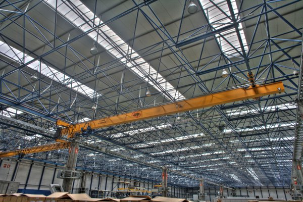
A space frame or space structure (3D truss) is a rigid, lightweight, truss-like structure constructed from interlocking struts in a geometric pattern. Space frames can be used in architecture and structural engineering to span large areas with few interior supports. Like the truss, a space frame is strong because of the inherent rigidity of the triangle; flexing loads (bending moments) are transmitted as tension and compression loads along the length of each strut.

Chief applications include buildings and vehicles.

History

[edit]

From 1898 to 1908, Alexander Graham Bell developed space frames based on tetrahedral geometry, primarily for nautical and aeronautical engineering. He invented the tetrahedral truss.[1][2]

Max Mengeringhausen developed the space grid system called MERO (acronym of MEngeringhausen ROhrbauweise) in 1943 in Germany, the first use of space trusses in architecture.[3] The commonly used method, still in use[as of?], has individual tubular members connected at node joints (ball shaped) and variations such as the space deck system, octet truss system, and cubic system.

Stéphane de Chateau in France invented the Tridirectional SDC system (1957), Unibat system (1959), and Pyramitec (1960).[4][5] A method of tree supports was developed to replace the individual columns.[6]

Buckminster Fuller patented the octet truss (U.S. patent 2,986,241) in 1961[7] while focusing on architectural structures.

Gilman's Tetrahedral Truss of 1980 was developed by John J. Gilman, a material scientist known for his work on the molecular matrices of crystalline solids. Gilman was an admirer of Buckminster Fuller's architectural trusses, and developed a stronger matrix, in part by rotating an alignment of tetrahedral nodes in relation to each other.

Design methods

[edit]

Space frames are typically designed using a rigidity matrix. The special characteristic of the stiffness matrix in an architectural space frame is the independence of the angular factors. If the joints are sufficiently rigid, then the angular deflections can be neglected, simplifying the calculations.

Overview

[edit]
Simplified space frame roof with the half-octahedron highlighted in blue

The simplest form of space frame is a horizontal slab of interlocking square pyramids and tetrahedra built from aluminium or tubular steel struts. A stronger form is composed of interlocking tetrahedra in which all the struts have unit length, referred to as an isotropic vector matrix or, in a single unit width, an octet truss. More complex variations change the lengths of the struts to curve the overall structure or may incorporate other geometrical shapes.

Types

[edit]

Space frames can be classified in various ways.[8]

Curvature classification

  • Space plane covers: These spatial structures are composed of planar substructures. Their behavior is similar to that of a plate in which the deflections in the plane are channeled through the horizontal bars and the shear forces are supported by the diagonals.[9]
This train station in India is supported by a barrel vault structure
  • Barrel vaults: This type of vault has a cross section of a simple arch. Usually this type of space frame does not need to use tetrahedral modules or pyramids as a part of its backing.
  • Spherical domes and other compound curves usually require the use of tetrahedral modules or pyramids and additional support from a skin.

Classification by the arrangement of its elements

  • Single-layer grid: All elements are located on the surface to be approximated.
  • Double-layer grid: Elements are organized in two layers parallel to each other at a certain distance apart. Each of the layers forms a lattice of triangles, squares, or hexagons in which the projection of the nodes in a layer may overlap or be displaced relative to each other. Diagonal bars connect the nodes of both layers in different directions in space. In this type of meshe, the elements are associated into three groups: upper cordon, cordon, and cordon lower diagonal.
  • Triple-layer grid: Elements are placed in three parallel layers, linked by the diagonals. They are almost always flat.

Other examples classifiable as space frames include:

  • Pleated metallic structures: Emerged to try to solve the problems that formwork and pouring concrete had their counterparts. Typically run with welded joint, but may raise prefabricated joints, a fact which makes them space meshes.
  • Hanging covers: Designs on the cable taut, spine, and the catenary arch (inverted funicular) show their ability to channel forces theoretically better than any alternative, and they have an infinite range of possibilities for composition and adaptability to any type of plant cover. However, imprecisions in shape risk having the loaded strand bend to unexpected stresses; mitigation of this problem requires pre-compression and pre-stressing elements. In most cases, they tend to be the cheapest solution that best fits the acoustics and ventilation of the covered enclosure. They are vulnerable to vibration.
  • Pneumatic structures: Closure membranes subjected to a pressurized state may be considered within this group.

Applications

[edit]

Buildings

Vehicles:

    • Aircraft
    • Automobiles
    • Motorcycles
    • Bicycles
    • Spacecraft

Architectural design elements

Construction

[edit]

Space frames are a common feature in modern building construction; they are often found in large roof spans in modernist commercial and industrial buildings.

Examples of buildings based on space frames include:

Large portable stages and lighting gantries are also frequently built from space frames and octet trusses.

Vehicles

[edit]

Aircraft

[edit]
Yeoman YA-1 vsCAC CA-6 Wackett frames
Bell 47G

The CAC CA-6 Wackett and Yeoman YA-1 Cropmaster 250R aircraft were built using roughly the same welded steel-tube fuselage frame.

Many early "whirlybird"-style exposed-boom helicopters had tubular space-frame booms, such as the Bell 47 series.

Cars

[edit]
Jaguar C-Type automobile racer tubular space frame (1951-1953)
Mercedes-Benz 300 SL sport car's tubular frame (1954-1957)
Chilean kit car showing off its space frame structure (2013)

Space frames are sometimes used in the chassis designs of automobiles and motorcycles. In both a space-frame and a tube-frame chassis, the suspension, engine, and body panels are attached to a skeletal frame of tubes, and the body panels have little or no structural function. By contrast, in a unibody or monocoque design, the body serves as part of the structure.

Tube-frame chassis pre-date space frame chassis and are a development of the earlier ladder chassis. The advantage of using tubes rather than the previous open-channel sections is that they resist torsional forces better. Some tube chassis were little more than a ladder chassis made with two large-diameter tubes, or even a single tube as a backbone chassis. Although many tubular chassis developed additional tubes and were even described as "space frames", their design was rarely correctly stressed as a space frame, and they behaved mechanically as a tube-ladder chassis, with additional brackets to support the attached components. The distinction of the true space frame is that all the forces in each strut are either tensile or compressive, never bending.[10] Although these additional tubes did carry some extra load, they were rarely diagonalised into a rigid space frame.[10]

An earlier contender for the first true space-frame chassis is the one-off Chamberlain 8 race "special" built by brothers Bob and Bill Chamberlain in Melbourne, Australia, in 1929.[11] Others attribute vehicles were produced in the 1930s by designers such as Buckminster Fuller and William Bushnell Stout (the Dymaxion and the Stout Scarab) who understood the theory of the true space frame from either architecture or aircraft design.[12]

A post-WW2 attempt to build a racing car space frame was the Cisitalia D46 of 1946.[12] This used two small-diameter tubes along each side, but they were spaced apart by vertical smaller tubes, and so were not diagonalised in any plane. A year later, Porsche designed their Type 360 for Cisitalia. As this included diagonal tubes, it can be considered a true space frame and arguably the first mid-rear engined design.[12]

In 1949, Robert Eberan von Eberhorst designed the Jowett Jupiter exhibited at that year's London Motor Show; the Jowett went on to take a class win at the 1950 Le Mans 24hr. Later, TVR, the small British car manufacturers, developed the concept and produced an alloy-bodied two-seater on a multi-tubular chassis, which appeared in 1949.

The space frame Jaguar C-Type racing car was introduced in 1951 and produced through 1953. In 1954 Mercedes-Benz introduced the space frame 300 SL "Gullwing" sports car, the fastest production car of its day.

A large number of kit cars use space frame construction, because manufacturing them in small quantity requires only simple and inexpensive jigs, and it is relatively easy for an amateur designer to achieve good stiffness with a space frame.

A drawback of the space-frame chassis is that it encloses much of the working volume of the car and can make access for both the driver and to the engine difficult. The Mercedes-Benz 300 SL "Gullwing" received its iconic upward-opening doors when its tubular space frame made using regular doors impossible.

Some space frames have been designed with removable sections, joined by bolted pin joints. Such a structure had already been used around the engine of the Lotus Mark III.[13] Although somewhat inconvenient, an advantage of the space frame is that the same lack of bending forces in the tubes that allow it to be modeled as a pin-jointed structure also means that creating such a removable section need not reduce the strength of the assembled frame.

Motorcycles and bicycles

[edit]
Moulton Bicycle at the Museum of Modern Art
2006 Ducati Monster S2R 1000

Tubular frames - often using the engine as a stressed member of the chassis - are commonplace in motorcycles, having been introduced in the 1970s in such bikes as the Honda CBX, which debuted in 1978. Italian motorbike manufacturer Ducati extensively uses them.

Space frames have also been used in bicycles, which readily favor stressed triangular sectioning.

See also

[edit]

References

[edit]
Revisions and contributorsEdit on WikipediaRead on Wikipedia
from Grokipedia
A space frame is a rigid, , three-dimensional truss-like constructed from interlocking linear struts, typically arranged in a geometric of interconnected triangles, enabling efficient load distribution and spanning large areas without intermediate supports. These structures transfer forces axially through their members, providing high strength-to-weight ratios and versatility in architectural design. Composed primarily of , aluminum, or composite tubes connected at nodes via specialized joints such as ball or hemispherical connectors, space frames are prefabricated for rapid on-site assembly. The development of space frames traces back to the late 19th and early 20th centuries, when experimented with tetrahedral geometries from 1898 to 1908, initially applying them to nautical and aeronautical engineering challenges like kites and hydroplanes. In the mid-20th century, American engineer and architect advanced the concept in the 1950s through his work on domes and octet-truss systems, emphasizing efficiency and for large-scale enclosures. Subsequent growth over the past half-century has been driven by innovations in high-strength materials, welding techniques, and and analysis, allowing for more complex and expansive applications worldwide. Space frames are categorized by layer arrangement—single-layer grids for simpler spans, double- or multi-layer configurations for greater rigidity—and by overall form, including barrel vaults, spherical polyhedra, and planar roofs. Notable systems include the forged steel ball-and-tube System III for unlimited spans and versatile shapes, and the hemispherical node type suited for spans up to 90 feet with variable geometries. Their design relies on isotropic vector matrices to ensure uniform stress distribution, though they demand precise fabrication to maintain structural integrity. Among the primary benefits of space frames are their exceptional lightweight —often 50-70% lighter than traditional solid roofs—facilitating easy transportation, seismic resilience through even load sharing, and the creation of expansive, column-free interiors ideal for . Construction is speedy due to modular , and they offer aesthetic flexibility with translucent or curved forms. Common applications span sports arenas, airport terminals, exhibition pavilions, and industrial hangars, with iconic examples such as the Eden Project's biomes in , , the Sochi International Airport in , and the McCormick Place East expansion in , USA, demonstrating their capacity for innovative, large-scale enclosures.

Overview

Definition and Principles

A space frame is a rigid, , truss-like structure composed of interconnected struts or bars arranged in a geometric to form a three-dimensional framework capable of spanning large areas. It consists of linear elements, such as or aluminum tubes, connected at nodes to create a system where forces are transferred in a three-dimensional manner, often manifesting as flat or curved surfaces. The fundamental principles of space frames revolve around triangulation for rigidity, efficient load distribution through axial forces in members, and the seamless integration of structural form and function in architectural and engineering applications. Triangulation, achieved via repeating triangular units, ensures inherent stability by preventing deformation under load, as each triangle maintains its shape under axial tension or compression. Loads are distributed omnidirectionally across the framework, with all members contributing equally to resist forces, unlike the sequential transfer in planar systems; this axial loading—primarily tension or compression—minimizes bending moments and enhances overall efficiency. Space frames achieve exceptionally high strength-to-weight ratios through their three-dimensional connectivity, which provides greater and compared to two-dimensional trusses that rely on planar arrangements for support. In 2D trusses, forces propagate primarily in one plane, limiting span capabilities and material efficiency, whereas the 3D grid of space frames allows for lighter members to cover vast areas with minimal deflection. Basic geometric patterns, such as tetrahedral or octahedral units, serve as the building blocks, enabling modular assembly and scalable designs that optimize material use. Variants like domes, popularized by , exemplify space frame applications in large-span enclosures.

Components and Geometry

Space frames are constructed from primary components that enable their three-dimensional rigidity and load distribution: struts, nodes, and cladding interfaces. Struts serve as the linear members, typically tubular elements such as circular hollow sections made of steel or aluminum, designed to resist axial forces in tension or compression. These struts form the framework's edges, interconnecting at nodes to create a triangulated lattice that approximates a continuous surface. Cladding interfaces, often integrated at the top chords or directly at nodes, allow attachment of panels, sheets, or glazing systems, such as insulated panels or sheets, to provide weatherproofing and aesthetic finishes without compromising the structural integrity. Nodes act as the critical joints or hubs where multiple struts converge, facilitating efficient force transfer through the structure. Common types include bolted nodes, which use high-strength bolts or friction-grip connections to join struts via end fittings, allowing for adjustability and disassembly; welded nodes, where struts are fused to plates or intersections for permanent rigidity; and spherical hubs, such as solid or hollow ball joints that accommodate up to 18 struts in multi-directional orientations, ensuring that forces meet at the node's center to minimize eccentricity and enable purely axial load paths. In bolted and spherical systems, connection mechanics rely on precise alignment of strut axes with the node's , promoting uniform stress distribution and preventing moments at joints. Welded nodes, by contrast, provide seamless integration but require careful fabrication to avoid residual stresses. The geometry of space frames is defined by configurations that optimize spatial coverage and stability, including space grids, domes, and vaults. Space grids typically feature rectangular patterns, such as square-on-square layouts, or triangular arrangements, like offset triangle-on-triangle modules, which provide planar or slightly curved surfaces for flat roofs spanning large areas. Domes adopt spherical geometries for hemispherical enclosures or hyperbolic forms for saddle-shaped roofs, leveraging curved chord arrangements to distribute loads radially. Vaults employ cylindrical profiles, often as barrel shapes, to create elongated arched coverings. In all configurations, chord directions—comprising top, bottom, and diagonal members—are aligned with principal stress paths, directing forces along the lattice's axes to enhance and reduce material use by following natural load trajectories. Assembly of space frames emphasizes modular combined with on-site bolting for rapid erection and . Components like pyramidal units or preassembled grid sections are fabricated off-site in standardized sizes, enabling transportation of lightweight modules that can span up to 90 meters when lifted into place. On-site, bolting secures the interconnections, often using threaded or friction connections at nodes, which allows for precise adjustments and minimizes time while maintaining structural precision. This logic supports efficient assembly in diverse architectural spans, building on principles for overall stability.

History

Early Developments

The origins of space frame technology trace back to 19th-century engineering experiments with systems, particularly in iron frameworks for large-scale structures. German engineer Johann Wilhelm Schwedler advanced early concepts through his 1851 publication on the theory of bridge systems, which introduced analytical methods for designing rigid planar frameworks capable of spanning significant distances while distributing loads efficiently. Schwedler's work built on prior lattice designs and emphasized the geometric arrangement of members to achieve , influencing subsequent dome and roof constructions in . Later contributions by Schwedler in the 1860s, such as his designs, extended these principles to three-dimensional lattice structures. In the and , European innovations further refined these ideas toward modular, prefabricated systems. In , Max Mengeringhausen pioneered tubular construction techniques, with his early Merkblätter system around 1925 providing standardized guidelines for interconnecting pipes in spatial arrays, setting the stage for scalable 3D trusses. Concurrent developments occurred in , where engineers explored similar lightweight frameworks, contributing to the evolution of space grids amid growing demands for efficient industrial buildings. These efforts emphasized nodal connections and geometric patterns to enhance rigidity without excessive material use. Additionally, in the late 19th and early 20th centuries, experimented with tetrahedral geometries from 1898 to 1908, applying them to structures like kites and hydroplanes, which influenced later space frame designs. World War II significantly influenced space frame advancement through adaptations from aircraft engineering, where lightweight 3D trusses became essential for high-strength, low-weight designs. British engineer Barnes Wallis's , implemented in the bomber from 1936 onward, utilized a basket-weave of interlocking struts forming a robust space frame that resisted battle damage while minimizing weight—principles later extended to temporary military hangars requiring rapid assembly and large clear spans. Postwar emergence marked a pivotal shift, with American architect and engineer securing a key for the on December 12, 1951 (U.S. No. 2,682,235, issued June 29, 1954), which applied space frame geometry to create expansive, self-supporting enclosures using triangulated struts for optimal strength-to-weight ratios. This innovation, rooted in earlier theories, demonstrated the practical potential of space frames for architectural applications, bridging wartime technologies to civilian use.

Key Milestones and Modern Evolution

The post-World War II era marked a pivotal advancement in space frame technology, with the 1950s and 1960s witnessing the first large-scale implementations that demonstrated their potential for expansive, lightweight enclosures. A landmark example was the United States Pavilion at Expo 67 in Montreal, Canada, designed by R. Buckminster Fuller as a 76-meter-diameter geodesic dome space frame, which showcased the structural efficiency of triangulated grids for covering vast areas without internal supports. This structure, completed in 1967, utilized over 1,800 acrylic panels supported by a network of aluminum struts, highlighting space frames' ability to integrate aesthetics with engineering prowess. Concurrently, Fuller's development of the octet-truss system in the 1950s revolutionized space frame geometry; patented in 1961, it employed repeating tetrahedral and octahedral units to achieve isotropic strength, enabling applications in hangars and enclosures with spans exceeding 100 meters. By the , these innovations gained traction in architectural projects worldwide, solidifying space frames' role in temporary and permanent large-span roofs. The and brought efforts to ensure reliability and . The International Association for Shell and Spatial Structures (IASS) established key guidelines through its Working Group on Spatial Steel Structures in 1984, providing recommendations for analysis, , and fabrication of space frames to address and integrity under dynamic loads. These were expanded in the 1986 IASS Symposium on Shells, Membranes, and Space Frames, which outlined protocols for seismic resistance and modular assembly, influencing global codes like Eurocode 3. Software integration accelerated this period; early finite element analysis tools, such as STRUDL developed in the , enabled precise modeling of complex node connections, reducing iterations compared to manual methods. By the , integrated CAD-FEA platforms like SAP2000 became standard, facilitating optimization of member sizes and topologies for cost efficiency. Entering the , space frame evolution emphasized adaptability and , with innovations in curved members allowing for non-Euclidean geometries in undulating roofs and facades. A 2025 study introduced flat-foldable nodes inspired by principles for frames, enabling of complex forms with fewer unique components, as demonstrated in designs. Sustainable materials gained prominence, with often comprising high recycled content to lower embodied carbon while maintaining high tensile strengths. In , space frames integrated into high-rise buildings surged, with practices incorporating them as diagrid exoskeletons in towers exceeding 300 meters, such as the National Stadium, enhancing lateral stability without added mass. Digital tools further transformed design; parametric modeling via software like in Rhino3D, adopted widely since 2015, allows real-time generation of custom space frame variants, optimizing for wind loads and material use in freeform , filling gaps in traditional computational approaches.

Types

Single-Layer Space Frames

Single-layer space frames consist of structural members arranged in a single plane or two closely spaced parallel planes, forming a grid pattern that approximates a flat or shallow surface. These configurations typically feature orthogonal or diagonal grids derived from square or triangular bases, with diagonal bracing elements incorporated for stability, such as in N-truss or X-truss patterns where members intersect to create triangular units resistant to shear. The nodes connect these members rigidly or semi-rigidly, allowing the frame to primarily resist axial forces while providing two-way spanning capability for efficient load distribution. The primary advantages of single-layer space frames include simpler fabrication processes due to fewer components and layers, resulting in lower material consumption compared to deeper systems. They are particularly suitable for spans up to approximately 40 meters, such as in coverings with minimal structural depth, where the span-to-depth ratio can reach about 30 under typical loadings. This enables lightweight with high , facilitating modular assembly and reduced on-site labor. However, single-layer space frames exhibit reduced structural redundancy relative to multi-layer variants, making them more vulnerable to progressive failure if key members are compromised. They are particularly prone to under torsional or unsymmetrical loads, as the single plane limits torsional resistance and can lead to local or overall instability in larger configurations. Representative examples include Resch grid patterns, which derive from square or triangular tessellations to form deployable or rigid single-layer networks, often used in planar applications for their geometric efficiency in approximating curved or flat surfaces without additional depth. Other configurations, like the Nodus system's N-truss grids, have been applied in exhibition halls with spans around 28 meters, demonstrating practical implementation in shallow roof structures.

Multi-Layer Space Frames

Multi-layer space frames consist of two or more parallel layers of interconnected structural members, forming a three-dimensional grid that provides enhanced depth and rigidity compared to . In a typical double-layer configuration, top and bottom chord layers are linked by vertical or inclined web members, creating basic tetrahedral or square pyramidal units that distribute loads axially and enable the realization of curved geometries such as spherical or hyperbolic surfaces. These units are assembled into larger modules, with joints often designed as hinged connections to minimize in individual members while relying on the overall framework for stability. Key subtypes of multi-layer space frames include geodesic domes, barrel vaults, and Schwedler systems, each adapted to specific s and load conditions. Geodesic domes derive from the icosahedral subdivision of a , where the surface is triangulated into facets; the frequency of subdivision—such as 2V (dividing each edge into two segments) or 3V (three segments)—determines the dome's approximation to a true , the length variation of struts, and the overall structural efficiency. Barrel vaults feature a cylindrical , with multi-layer grids braced by patterns like Warren trusses or lamella arrangements along the barrel's length, suitable for elongated enclosures. Schwedler systems, a form of braced dome, combine meridional ribs radiating from the apex with concentric horizontal rings, further subdivided into triangular panels for added stiffness in . The geometric arrangement in multi-layer space frames emphasizes chord members in the outer layers for primary tension and compression, supplemented by diagonal web members that resist shear and torsion at angles typically between 30° and 60°. This chord-diagonal interplay allows for precise control of module sizes and offsets, such as square-on-square grids in double layers, optimizing the framework for complex forms. Advantages stem from this depth, including superior load-bearing capacity for spans over 100 meters and improved distribution of bending moments, which reduces localized stresses and enhances overall rigidity for large-scale, aesthetically versatile designs like curved roofs or enclosures. Unlike single-layer grids, which serve as simpler precursors for flat spans, multi-layer systems have been briefly referenced in iconic applications such as Expo pavilions for their form-finding capabilities.

Design and Analysis

Structural Analysis Methods

Structural analysis of space frames involves evaluating the stability, deformation, and internal forces under applied loads, leveraging methods tailored to their three-dimensional truss-like geometry. These structures, assumed to follow geometries such as single-layer or multi-layer configurations from prior discussions, require approaches that account for high degrees of indeterminacy and spatial member interactions. Preliminary assessments often begin with simplified hand calculations to estimate overall behavior and member sizing, providing quick insights before advanced computations. For instance, basic force distribution can be approximated using equilibrium equations at joints, treating the frame as a pin-jointed system. The matrix stiffness method serves as a foundational technique for precise truss analysis in space frames, formulating the global stiffness matrix from individual member contributions to solve for displacements and forces. This direct stiffness approach assembles element stiffness matrices in local coordinates, transforms them to global coordinates using direction cosines, and solves the system Ku=F\mathbf{K} \mathbf{u} = \mathbf{F}, where K\mathbf{K} is the global stiffness matrix, u\mathbf{u} are nodal displacements, and F\mathbf{F} are applied forces. For a typical space truss member, the axial force FF relates to deformation δ\delta via F=AELδF = \frac{AE}{L} \delta, with AA as cross-sectional area, EE as modulus of elasticity, and LL as member length; stability is assessed by ensuring the determinant of K\mathbf{K} remains positive for non-singular solutions under incremental loading. This method efficiently handles the multiple degrees of freedom (up to six per node in 3D) inherent to space frames. Finite element analysis (FEA) extends these principles for comprehensive of space frames, discretizing the structure into beam or elements to capture complex behaviors like geometric nonlinearity and large displacements. In FEA, space frames are modeled with 3D frame elements that include axial, torsional, and , enabling of rigidity and support conditions. The method solves the equilibrium equations iteratively, often using Newton-Raphson for nonlinear cases, to predict stress distributions and modes. For example, NASA-developed parallel FEA procedures have optimized space frame designs by reducing computational time for large-scale trusses. Key considerations in space frame analysis include under compressive loads and responses to dynamic excitations. analysis adapts formula for 3D contexts, where the critical force for a member is Pcr=π2EIL2P_{cr} = \frac{\pi^2 E I}{L^2} (with II as ), but incorporates geometric matrices to evaluate frame-wide modes via eigenvalue solutions of (K+λKg)u=0(\mathbf{K} + \lambda \mathbf{K}_g) \mathbf{u} = 0, with λ\lambda as the buckling factor and Kg\mathbf{K}_g the geometric . , such as wind or seismic forces, requires to compute natural frequencies and mode shapes, ensuring avoidance. Software tools like SAP2000 and facilitate these computations, integrating FEA with automated meshing and visualization for practical engineering workflows.

Materials and Fabrication Techniques

Space frames are predominantly constructed using , particularly high-strength alloys such as S355, which offers a minimum yield strength of 355 MPa, enabling efficient load-bearing capacity while maintaining structural integrity. This material's high tensile strength and make it suitable for withstanding complex forces in large-scale applications, though it requires protective measures against due to its susceptibility in humid or coastal environments. Aluminum alloys serve as an alternative for scenarios demanding reduced weight, providing a favorable strength-to-weight ratio and inherent corrosion resistance through the formation of a passive layer on the surface. Emerging composite materials, such as carbon fiber reinforced polymers, are increasingly adopted in the 2020s to enhance by offering superior and lower environmental impact via reduced material usage and recyclability. Fabrication of space frames emphasizes prefabrication in controlled factory settings to ensure precision and quality, where structural modules are produced off-site before transportation to the construction site. Key connection methods include welding, such as TIG welding for assembling joints from steel plates, and bolting with high-grade fasteners like Grade 8 bolts to secure struts at nodes, allowing for both permanent and demountable assemblies. Surface treatments, including hot-dip galvanizing for steel components and polyester powder coating for joints, are applied to enhance corrosion resistance and longevity, with galvanizing providing a sacrificial zinc layer that protects against atmospheric degradation. Advanced techniques like CNC machining, including waterjet cutting, are employed to fabricate precision struts and nodes with tolerances as tight as ±0.01 inches, ensuring geometric accuracy essential for load distribution. Modular assembly sequences facilitate on-site erection by minimizing labor through pre-assembled kits of standardized elements, such as orthogonal gussets and variable-length struts, which interlock via bolted connections. measures, including finite element analysis validation and tolerance checks during fabrication, verify integrity and overall structural prior to deployment. Recent trends focus on , incorporating from sources like repurposed to reduce and embodied carbon, while 3D-printed nodes enable customized, lightweight connectors using recyclable polymers or metals. These innovations address environmental concerns by optimizing material efficiency and supporting principles in space frame construction.

Applications

Architectural Structures

Space frames are extensively employed in architectural structures to achieve expansive, column-free interiors in buildings such as arenas, exhibition halls, and airport terminals, enabling spans greater than 150 meters without intermediate supports. These structures provide lightweight yet robust roofing solutions that maximize usable space and facilitate flexible layouts for public gatherings and events. For instance, the in , completed in , utilizes a lattice-like space system for its iconic glass atrium, spanning over 200 meters and supporting multiple levels of exhibition and performance spaces. A prominent example is the in the , opened in 2001, where hexagonal space frames form the skeletal structure of its biomes—massive enclosures mimicking diverse ecosystems. These frames, constructed from tubes connected by bolted joints, offer advantages in natural lighting through their transparent cladding and enhanced seismic resistance via the distributed load paths in the geometric grid, which allows flexibility under dynamic forces. Similarly, exhibition halls like Chicago's employ space frames to create vast, adaptable floors for trade shows, while airport terminals such as London's Stansted Airport feature inverted pyramid-supported space frames spanning 76 meters for efficient passenger flow. In design integrations, space frames are often clad with ethylene tetrafluoroethylene () panels, as seen in the Eden Project's biomes, where triple-layered cushions provide lightweight, translucent enclosures that transmit up to 95% of visible light while maintaining thermal efficiency. Fireproofing standards for these structures typically involve coatings on steel members to achieve fire-resistance ratings of 1 to 2 hours per ASTM E119 or equivalent international codes, ensuring occupant safety in large public venues. For spans exceeding 50 meters, space frames deliver cost benefits through material efficiency, reducing manufacturing costs by about 32% compared to traditional frame structures. Multi-layer space frames are particularly suited for dome configurations in architectural enclosures, providing uniform stress distribution over curved surfaces.

Vehicle and Transportation Systems

In automotive applications, space frames provide a lightweight yet rigid structure, particularly in high-performance sports cars. The , introduced in 1987, utilized a tubular steel space frame to achieve exceptional torsional rigidity while maintaining a low weight, enhancing handling and structural integrity under dynamic loads. This design contributed to the vehicle's reputation for superior crash energy absorption through its tubular configuration, which distributes impact forces effectively compared to earlier ladder frames. Aviation has adopted space frame principles in fuselage construction to optimize weight and strength. The incorporates composite materials, such as Hexcel's HexMC, in its frames, including window frames and structural elements, resulting in approximately 50% weight savings over traditional aluminum equivalents. These space frame-like assemblies improve by reducing overall aircraft mass and enhance durability through superior damage tolerance. In motorcycles, Ducati's trellis frame design, a variant of tubular space framing, integrates steel tubes around the engine for high rigidity and precise handling, as seen in models like the Monster series. Space frames also appear in rail transportation for underframe structures in high-speed trains. The UK's (APT), a pioneering tilting project from the and 1980s, employed space frame construction in its power cars to support the lightweight body while accommodating high-speed dynamics. For pedestrian bridges, space frames offer effective vibration damping due to their geometric efficiency; a large-scale pultruded glass fiber reinforced polymer (GFRP) space frame pedestrian bridge demonstrated low vibration amplitudes under , with fatigue performance suitable for pedestrian traffic. Overall, space frames in and transportation systems reduce structural weight by up to 50% in composite applications like aircraft fuselages compared to metallic alternatives, leading to improved and capacity. They are particularly adapted for dynamic loads, such as vibrations and impacts, through their truss-like distribution of forces. Single-layer space frames are often used in flat designs for vehicles, drawing from early influences like the fabric-covered space frames in aircraft.

Industrial and Specialized Uses

Space frames find extensive application in industrial settings where large spans, lightweight construction, and resistance to dynamic loads are essential. In crane gantries, these structures are modeled as space frames to optimize load distribution and stability during heavy lifting operations, enabling efficient handling of materials in environments. Warehouse roofs often incorporate space frame designs to achieve long, unobstructed spans up to 100 meters, supporting heavy storage loads while minimizing material use through prefabricated components. For oil rig platforms in harsh marine conditions, x-braced space frames are fixed to the to provide robust support against , wind, and wave forces, ensuring operational integrity over extended periods. Temporary structures benefit from the modular and rapid-assembly nature of space frames, facilitating quick deployment in transient scenarios. At the 1967 Expo, numerous pavilions utilized steel space frames for their theme exhibitions, such as the Dutch pavilion's aluminum tubing assembly of 57,000 pieces forming expansive, lightweight enclosures that could be erected efficiently for the event's duration. Similarly, the German pavilion employed Frei Otto's innovative space frame tent design to cover exhibition areas, demonstrating the system's versatility for short-term, large-scale coverings. In disaster relief, space frames enable the construction of portable shelters with long spans and minimal foundations, allowing for swift setup of medical or housing facilities in affected areas, though specific implementations often adapt commercial modular kits for such purposes. Specialized uses extend space frames into high-precision and extreme-environment applications. The James Webb Space Telescope's backplane employs a composite space-frame structure to support its 18 hexagonal mirrors, providing one-millimeter stability in cryogenic conditions at the L2 Lagrange point since its 2021 deployment. In renewable energy, post-2020 installations have integrated space frames into solar trackers, where lightweight designs minimize steel usage while maximizing panel orientation efficiency, as seen in one-axis systems that enhance energy yield by 15-25% over fixed mounts. Wind turbine bases also leverage space frame towers to optimize load transfer in offshore gravity foundations, reducing weight and improving deployment logistics in challenging seabed conditions. Innovations in space frame applications include robotic assembly techniques for factory production and biomedical adaptations. Robotic systems enable automated construction of modular space frames in industrial factories, using human-robot collaboration to assemble timber or trusses with high precision, reducing errors and assembly time by integrating design feedback loops. In biomedical fields, space frame-inspired scaffolds, modeled as representative volume elements (RVEs) with cylindrical beams, support by mimicking bone porosity and enabling cell growth in nanoporous biopolymeric structures produced via processes.

References

Add your contribution
Related Hubs
User Avatar
No comments yet.