Hubbry Logo
Trailing edgeTrailing edgeMain
Open search
Trailing edge
Community hub
Trailing edge
logo
8 pages, 0 posts
0 subscribers
Be the first to start a discussion here.
Trailing edge
Trailing edge
from Wikipedia
Cross section of an aerodynamic surface with the trailing edge emphasised
An American Aviation AA-1 Yankee being refuelled. Its wing trailing edge can be seen with aileron (deployed downwards) and flap.

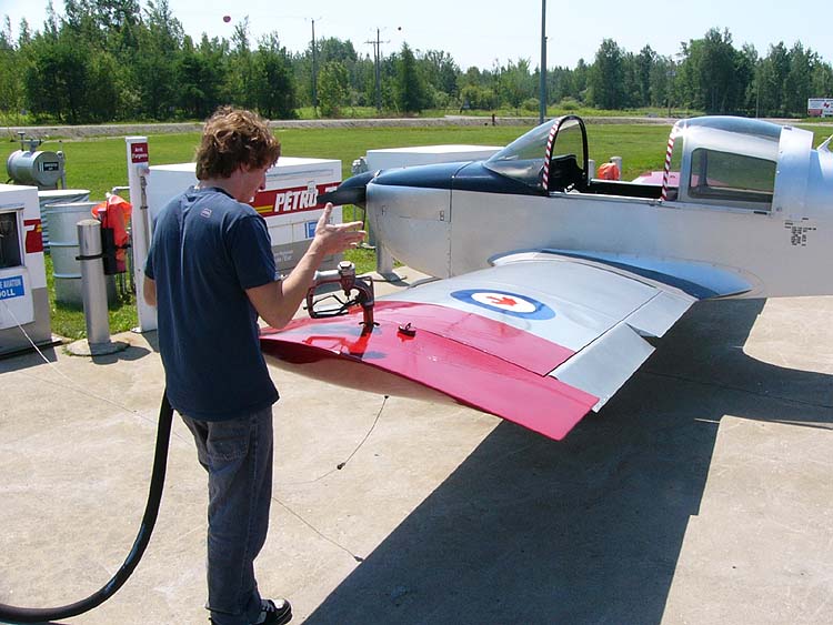
The trailing edge of an aerodynamic surface such as a wing is its rear edge, where the airflow separated by the leading edge meets.[1] Essential flight control surfaces are attached here to control the direction of the departing air flow, and exert a controlling force on the aircraft.[2] Such control surfaces include ailerons on the wings for roll control, elevators on the tailplane controlling pitch, and the rudder on the fin controlling yaw. Elevators and ailerons may be combined as elevons on tailless aircraft.

The shape of the trailing edge is of prime importance in the aerodynamic function of any aerodynamic surface. A sharp trailing edge is always employed in an airfoil.[3] George Batchelor has written about:

“ ... the remarkable controlling influence exerted by the sharp trailing edge of an aerofoil on the circulation.”[4]

Extensions

[edit]

Other sharp-edged surfaces that are attached to the trailing edges of wings or control surfaces include:

  • On control surfaces:
  • Other surfaces:

Other equipment that may be attached to the trailing edges of wings include:

Trailing edge shape

[edit]

The trailing edge is where the upper and lower surfaces of a wing meet. The angle between the upper and lower surfaces at the trailing edge is called the trailing edge angle. If the trailing edge angle is zero it is described as a cusped trailing edge.[5]

In two-dimensional flow around a uniform wing of infinite span, the slope of the lift curve is determined primarily by the trailing edge angle. The slope is greatest if the angle is zero; and decreases as the angle increases.[6][7] For a wing of finite span, the aspect ratio of the wing also significantly influences the slope of the curve. As aspect ratio decreases, the slope also decreases.[8]

References

[edit]
Revisions and contributorsEdit on WikipediaRead on Wikipedia
from Grokipedia
The trailing edge of a lifting surface, such as , , blade, or , is the rearmost edge where the flow initially separated by the rejoins after passing over the surface. This edge plays a critical role in determining lift, drag, and overall efficiency by influencing how the departs the surface, with its affecting factors like and pressure distribution. In , the trailing edge is often modified—such as through , serrations, or cooling features—to balance , , and , particularly in high-speed or turbulent conditions. Trailing edges are integral to control surfaces, including flaps, ailerons, and elevators, which are typically located along this rear boundary to enable maneuvers like takeoff, landing, and banking by altering camber and lift. For instance, trailing-edge flaps significantly increase wing camber and lift during low-speed operations. Common configurations include sharp trailing edges, which minimize noise and avoid when the edge thickness relative to displacement is low (h/δ* ≤ 0.3), and blunt or serrated designs used in applications like wind turbines and landing gear to attenuate broadband noise. In propeller blades, the trailing edge ensures smooth flow rejoining to reduce drag and enhance efficiency. Overall, optimizing the trailing edge is essential for modern , as it directly impacts , acoustic signatures, and structural integrity under operational stresses.

Fundamentals

Definition

The trailing edge of an , , or is the rearmost point or line where the upper and lower surfaces converge, serving as the location where the separates and the flow detaches from the surface to form the downstream wake. This detachment marks the transition from attached viscous flow along the body to the free shear layer in the wake, distinguishing it from the where flow initially impinges and attaches. Geometrically, the trailing edge typically represents the intersection of the airfoil's upper and lower contours, forming the aft boundary of the chord line that extends from the . In practical designs, it often incorporates a finite thickness to accommodate constraints and structural demands, rather than a perfectly sharp cusp, which balances aerodynamic performance with durability. The physical role of the trailing edge in was advanced by Ludwig Prandtl's theory, presented in , which highlighted its role in confining viscous effects to thin layers near the surface and explained the formation of wakes downstream. Prandtl's work distinguished the trailing edge from the by emphasizing how flow attachment and detachment influence drag and lift in high-Reynolds-number flows over bodies like airfoils. Conceptually, the trailing edge can be illustrated as the convergence point of over an , where boundary layers from the upper (typically faster, lower pressure) and lower (slower, higher pressure) surfaces meet, detaching smoothly to trail as a wake that carries deficits and downstream. This geometric feature ensures that, under normal conditions, the boundary layers reach the trailing edge without premature separation, maintaining attached flow until detachment.

Physical Principles

At the trailing edge of an airfoil or hydrofoil, the boundary layers from the upper and lower surfaces converge, leading to flow separation that forms a wake region characterized by low momentum and velocity deficits downstream. This separation arises due to the inability of the viscous boundary layer to fully negotiate the sharp geometric discontinuity or pressure gradient at the edge, resulting in a shear layer instability that promotes wake formation. For blunt trailing edges, the separated shear layers undergo periodic vortex shedding, producing an alternating pattern of vortices known as a von Kármán vortex street, with the shedding frequency determined by the Strouhal number based on edge thickness and flow velocity. The generation of lift in such flows is governed by the Kutta-Joukowski theorem, which relates the lift per unit span LL' to the circulation Γ\Gamma around the body via the equation L=ρVΓ,L' = \rho V_\infty \Gamma, where ρ\rho is the fluid density and VV_\infty is the freestream velocity. This circulation originates from the bound vorticity within the boundary layers that is convected and shed into the wake at the trailing edge, creating a net rotational flow that deflects the streamlines and produces the perpendicular lift force. The theorem holds under the assumption of the Kutta condition, which enforces finite velocity and smooth flow departure at the trailing edge, ensuring the circulation remains steady in attached flows. The trailing edge significantly influences the overall pressure distribution by enabling pressure equalization between the upper (low-pressure) and lower (high-pressure) surfaces, as dictated by the where the difference ΔCp=0\Delta C_p = 0. This equalization mitigates severe adverse pressure gradients near the aft section, preventing upstream flow reversal within the that could otherwise cause premature separation and . In design, controlled pressure recovery at the trailing edge is essential to maintain boundary layer attachment through the aft region, avoiding the formation of reversed flow regions that degrade performance. Trailing edge noise stems primarily from the aerodynamic or hydrodynamic interactions of turbulent boundary layers and shed vortices with the edge, generating unsteady pressure fluctuations that radiate as . These interactions produce acoustic sources, with the noise power scaling as the fifth power of the convective of the turbulent eddies, and tonal components arising from periodic at the edge. In configurations like blades or jet flaps, impinging vortices from upstream further amplify the through scattering and additional shedding induced by the .

Design Considerations

Trailing Edge Shapes

Sharp trailing edges are characterized by a cusped or pointed geometry where the upper and lower surfaces meet at a finite angle, ideally approaching zero thickness to satisfy the in theory. This configuration ensures smooth flow departure from the , minimizing velocity discontinuities and promoting attached flow up to the trailing edge. In theoretical airfoils, such as thin symmetric profiles akin to the NACA 00xx series, sharp edges facilitate idealized lift generation via the Kutta-Joukowski theorem, where circulation is concentrated without significant viscous losses. The primary advantage of sharp trailing edges lies in their ability to reduce wake drag by limiting and at the aft end, which is crucial for high-lift applications in subsonic aerodynamics. This results in lower profile drag coefficients, often by enforcing equal pressure on the upper and lower surfaces at , thereby enhancing overall lift-to-drag ratios. However, practical limitations include manufacturing challenges, as achieving a truly sharp edge is difficult with conventional fabrication methods like or molding, leading to approximations with minimal rounding. Structurally, sharp edges compromise integrity due to reduced material thickness, increasing susceptibility to and impact damage in high-stress environments. Blunt trailing edges feature a small finite thickness, typically 0.25-1% of the chord length, providing a squared-off or rounded termination that deviates from the ideal sharp cusp. This design enhances structural robustness by increasing the cross-sectional area at the rear, allowing better load distribution and integration with control surfaces or reinforcements, which is particularly beneficial for thick airfoils in or supersonic regimes. Aerodynamically, blunt edges can mitigate certain tonal noise sources by disrupting coherent vortex structures in the wake, though they introduce base drag from at the blunt face. Drag penalties are generally modest at low speeds if the thickness is optimized, but improper sizing can significantly elevate profile drag compared to sharp counterparts, especially in subsonic flows. Serrated or cusped trailing edges incorporate periodic notches, such as sawtooth patterns, to modify the spectrum and achieve broadband suppression. These geometries diffuse vortical interactions by generating counter-rotating vortices along the serrations, effectively scattering acoustic energy and reducing trailing-edge by up to 5-7 dB over a wide frequency range, particularly in the 500-2000 Hz band relevant to human perception. In blades, serrated designs have been widely adopted, with sawtooth serrations demonstrating reductions of 2-5 dB at mid-frequencies while maintaining aerodynamic efficiency. The cusped variants, resembling bird-inspired fringes, further aid in by promoting gradual flow mixing, though they may slightly increase drag at high angles of attack due to enhanced spanwise flow. Optimization of trailing edge shapes involves balancing lift enhancement, drag minimization, and manufacturability, often guided by empirical criteria such as maintaining a small trailing edge angle to approximate Kutta-like behavior and limit separation-induced drag. Sharp edges prioritize low drag and high lift but falter in practicality, while blunt forms favor at the cost of moderate drag increases; serrated options excel in noise-critical applications like turbines, though they require precise geometric tuning to avoid lift penalties. These trade-offs are evaluated through and tests, ensuring shapes align with mission-specific goals like efficiency in or quiet operation in renewables.

Boundary Layer Effects

The boundary layer on an originates at the as a thin layer of viscous flow adhering to the surface, gradually thickening toward the trailing edge due to perpendicular to the flow direction. In regimes, this development is classically described by the Blasius solution, which provides a self-similar profile across the . The dimensionless uU=f(η)\frac{u}{U_\infty} = f'(\eta), where η=yUνx\eta = y \sqrt{\frac{U_\infty}{\nu x}}
Add your contribution
Related Hubs
User Avatar
No comments yet.