

Community hub
Recent from talks
Contribute something
Nothing was collected or created yet.
Milliradian
View on WikipediaThis article needs additional citations for verification. (April 2021) |
| Milliradian | |
|---|---|
 The PSO-1 reticle in a Dragunov sniper rifle has markings with 1-mrad spacing, which can be used to compensate for wind drift, impact correction or range estimation. | |
| General information | |
| Unit system | SI derived unit |
| Unit of | Angle |
| Symbol | mrad, mil |
| Named after | The metric prefix milli- (from Latin mille meaning "one thousand") and the radian |
| In units | Dimensionless with an arc length one thousandth of the radius, i.e. 1 mm/m or 1 m/km |
| Conversions | |
| 1 mrad in ... | ... is equal to ... |
| radians | 1/1000 rad |
| turns | 1/2000π turn |
| gradians | 1/5π ≈ 0.063662g |
| degrees | 9/50π ≈ 0.057296° |
| arcminutes | 54/5π ≈ 3.4377′ |
A milliradian (SI-symbol mrad, sometimes also abbreviated mil) is an SI derived unit for angular measurement which is defined as a thousandth of a radian (0.001 radian). Milliradians are used in adjustment of firearm sights by adjusting the angle of the sight compared to the barrel (up, down, left, or right). Milliradians are also used for comparing shot groupings, or to compare the difficulty of hitting different sized shooting targets at different distances. When using a scope with both mrad adjustment and a reticle with mrad markings (called an "mrad/mrad scope"), the shooter can use the reticle as a ruler to count the number of mrads a shot was off-target, which directly translates to the sight adjustment needed to hit the target with a follow-up shot. Optics with mrad markings in the reticle can also be used to make a range estimation of a known size target, or vice versa, to determine a target size if the distance is known, a practice called "milling".
Milliradians are generally used for very small angles, which allows for very accurate mathematical approximations to more easily calculate with direct proportions, back and forth between the angular separation observed in an optic, linear subtension on target, and range. In such applications it is useful to use a unit for target size that is a thousandth of the unit for range, for instance by using the metric units millimeters for target size and meters for range. This coincides with the definition of the milliradian where the arc length is defined as 1/1,000 of the radius. A common adjustment value in firearm sights is 1 cm at 100 meters which equals 10 mm/100 m = 1/10 mrad.
The true definition of a milliradian is based on a unit circle with a radius of one and an arc divided into 1,000 mrad per radian, hence 2,000 π or approximately 6,283.185 milliradians in one turn, and rifle scope adjustments and reticles are calibrated to this definition.[1] There are also other definitions used for land mapping and artillery which are rounded to more easily be divided into smaller parts for use with compasses, which are then often referred to as "mils", "lines", or similar. For instance there are artillery sights and compasses with 6,400 NATO mils, 6,000 Warsaw Pact mils or 6,300 Swedish "streck" per turn instead of 360° or 2π radians, achieving higher resolution than a 360° compass while also being easier to divide into parts than if true milliradians were used.
History
[edit]
The milliradian (approximately 6,283.185 in a circle) was first used in the mid-19th century by Charles-Marc Dapples (1837–1920), a Swiss engineer and professor at the University of Lausanne.[2] Degrees and minutes were the usual units of angular measurement but others were being proposed, with "grads" (400 gradians in a circle) under various names having considerable popularity in much of northern Europe. However, Imperial Russia used a different approach, dividing a circle into equilateral triangles (60° per triangle, 6 triangles in a circle)[citation needed] and hence 600 units to a circle.
Around the time of the start of World War I, France was experimenting with the use of millièmes or angular mils (6400 in a circle) for use with artillery sights instead of decigrades (4000 in a circle). The United Kingdom was also trialing them to replace degrees and minutes. They were adopted by France although decigrades also remained in use throughout World War I. Other nations also used decigrades. The United States, which copied many French artillery practices, adopted angular mils, later known as NATO mils. Before 2007 the Swedish defence forces used "streck" (6300 in a circle, streck meaning lines or marks) (together with degrees for some navigation) which is closer to the milliradian but then changed to NATO mils. After the Bolshevik Revolution and the adoption of the metric system of measurement (e.g. artillery replaced "units of base" with meters) the Red Army expanded the 600 unit circle into a 6000 mil circle. Hence the Russian mil has a somewhat different origin than those derived from French artillery practices.
In the 1950s, NATO adopted metric units of measurement for land and general use. NATO mils, meters, and kilograms became standard, although degrees remained in use for naval and air purposes, reflecting civil practices.
Mathematical principle
[edit]
_unit_circle_exaggerated.png)
Right: A milliradian corresponds to 1/1000 of the angle of a radian. (The image on the right is exaggerated for illustration, as a milliradian is much smaller in reality.)

Use of the milliradian is practical because it is concerned with small angles, and when using radians the small angle approximation shows that the angle approximates to the sine of the angle, that is . This allows a user to dispense with trigonometry and use simple ratios to determine size and distance with high accuracy for rifle and short distance artillery calculations by using the handy property of subtension: One mrad approximately subtends one meter at a distance of one thousand meters.

More in detail, because , instead of finding the angular distance denoted by θ (Greek letter theta) by using the tangent function

- ,

one can instead make a good approximation by using the definition of a radian and the simplified formula:

Since a radian is mathematically defined as the angle formed when the length of a circular arc equals the radius of the circle, a milliradian, is the angle formed when the length of a circular arc equals 1/1000 of the radius of the circle. Just like the radian, the milliradian is dimensionless, but unlike the radian where the same unit must be used for radius and arc length, the milliradian needs to have a ratio between the units where the subtension is a thousandth of the radius when using the simplified formula.
Approximation error
[edit]The approximation error by using the simplified linear formula will increase as the angle increases. For example, a
- 3.3×10⁻⁷% (or 3.3 parts per billion) error for an angle of 0.1 mrad, for instance by assuming 0.1 mrad equals 1 cm at 100 m[3]
- 0.03% error for 30 mrad, i.e. assuming 30 mrad equals 30 m at 1 km[4]
- 2.9% error for 300 mrad, i.e. assuming 300 mrad equals 300 m at 1 km[5]
| Calculation of percentage error for mrad |
|---|
|
|

The approximation using mrad is more precise than using another common system where 1′ (minute of arc) is approximated as 1 inch at 100 yards, where comparably there is a:
- 4.72% error by assuming that an angle of 1′ equals 1 inch at 100 yd[6]
- 4.75% error for 100′, i.e. assuming 100′ equals 100 in at 100 yd[7]
- 7.36% error for 1000′, i.e. assuming 1000′ equals 1000 inches at 100 yd[8]
| Calculation of percentage error for arcminutes |
|---|
|
where |


Sight adjustment
[edit].png)
Milliradian adjustment is commonly used as a unit for clicks in the mechanical adjustment knobs (turrets) of iron and scope sights both in the military and civilian shooting sports. New shooters are often explained the principle of subtensions in order to understand that a milliradian is an angular measurement. Subtension is the physical amount of space covered by an angle and varies with distance. Thus, the subtension corresponding to a mrad (either in an mrad reticle or in mrad adjustments) varies with range. Knowing subtensions at different ranges can be useful for sighting in a firearm if there is no optic with an mrad reticle available, but involves mathematical calculations, and is therefore not used very much in practical applications. Subtensions always change with distance, but an mrad (as observed through an optic) is always an mrad regardless of distance. Therefore, ballistic tables and shot corrections are given in mrads, thereby avoiding the need for mathematical calculations.
If a rifle scope has mrad markings in the reticle (or there is a spotting scope with an mrad reticle available), the reticle can be used to measure how many mrads to correct a shot even without knowing the shooting distance. For instance, assuming a precise shot fired by an experienced shooter missed the target by 0.8 mrad as seen through an optic, and the firearm sight has 0.1 mrad adjustments, the shooter must then dial 8 clicks on the scope to hit the same target under the same conditions.
Common click values
[edit]- General purpose scopes
- Gradations (clicks) of 1/4′, 1/10 mrad and 1/2′ are used in general purpose sights for hunting, target and long range shooting at varied distances. The click values are fine enough to get dialed in for most target shooting and coarse enough to keep the number of clicks down when dialing.
- Speciality scopes
- 0.25/10 mrad, 1/8′ and 0.5/10 mrad are used in speciality scope sights for extreme precision at fixed target ranges such as benchrest shooting. Some specialty iron sights used in ISSF 10 m, 50 m and 300 meter rifle come with adjustments in either 0.5/10 mrad or 0.25/10 mrad. The small adjustment value means these sights can be adjusted in very small increments. These fine adjustments are however not very well suited for dialing between varied distances such as in field shooting because of the high number of clicks that will be required to move the line of sight, making it easier to lose track of the number of clicks than in scopes with larger click adjustments. For instance to move the line of sight 0.4 mrad, a 0.1 mrad scope must be adjusted 4 clicks, while comparably a 0.05 mrad and 0.025 mrad scope must be adjusted 8 and 16 clicks respectively.
- Others
- 1.5/10 mrad and 2/10 mrad can be found in some short range sights, mostly with capped turrets, but are not very widely used.
Subtensions at different distances
[edit]_sight_adjustment.png)
Subtension refers to the length between two points on a target, and is usually given in either centimeters, millimeters or inches. Since an mrad is an angular measurement, the subtension covered by a given angle (angular distance or angular diameter) increases with viewing distance to the target. For instance the same angle of 0.1 mrad will subtend 10 mm at 100 meters, 20 mm at 200 meters, etc., or similarly 0.39 inches at 100 m, 0.78 inches at 200 m, etc.
Subtensions in mrad based optics are particularly useful together with target sizes and shooting distances in metric units. The most common scope adjustment increment in mrad based rifle scopes is 0.1 mrad, which are sometimes called "one centimeter clicks" since 0.1 mrad equals exactly 1 cm at 100 meters, 2 cm at 200 meters, etc. Similarly, an adjustment click on a scope with 0.2 mrad adjustment will move the point of bullet impact 2 cm at 100 m and 4 cm at 200 m, etc.
When using a scope with both mrad adjustment and a reticle with mrad markings (called a mrad/mrad scope), the shooter can spot his own bullet impact and easily correct the sight if needed. If the shot was a miss, the mrad reticle can simply be used as a "ruler" to count the number of milliradians the shot was off target. The number of milliradians to correct is then multiplied by ten if the scope has 0.1 mrad adjustments. If for instance the shot was 0.6 mrad to the right of the target, 6 clicks will be needed to adjust the sight. This way there is no need for math, conversions, knowledge of target size or distance. This is true for a first focal plane scope at all magnifications, but a variable second focal plane must be set to a given magnification (usually its maximum magnification) for any mrad scales to be correct.
When using a scope with mrad adjustments, but without mrad markings in the reticle (i.e. a standard duplex cross-hair on a hunting or benchrest scope), sight correction for a known target subtension and known range can be calculated by the following formula, which utilizes the fact that an adjustment of 1 mrad changes the impact as many millimeters as there are meters:

For instance:
- 20 mm/50 m = 0.4 mrad, or 4 clicks with a 1/10 mrad adjustment scope.
- 50 mm/1000 m = 0.05 mrad, or 1 click with a 0.05 mrad adjustment scope.
In firearm optics, where 0.1 mrad per click is the most common mrad based adjustment value, another common rule of thumb is that an adjustment of 1/10 mrad changes the impact as many centimeters as there are hundreds of meters. In other words, 1 cm at 100 meters, 2.25 cm at 225 meters, 0.5 cm at 50 meters, etc. See the table below
| Range | Subtension | |||
|---|---|---|---|---|
| 1 mrad | 1/10 mrad | |||
| 100 m | 100 mm | 10 cm | 10 mm | 1 cm |
| 200 m | 200 mm | 20 cm | 20 mm | 2 cm |
| 300 m | 300 mm | 30 cm | 30 mm | 3 cm |
| 400 m | 400 mm | 40 cm | 40 mm | 4 cm |
| 500 m | 500 mm | 50 cm | 50 mm | 5 cm |
| 600 m | 600 mm | 60 cm | 60 mm | 6 cm |
| 700 m | 700 mm | 70 cm | 70 mm | 7 cm |
| 800 m | 800 mm | 80 cm | 80 mm | 8 cm |
| 900 m | 900 mm | 90 cm | 90 mm | 9 cm |
| 1000 m | 1000 mm | 100 cm | 100 mm | 10 cm |
Adjustment range and base tilt
[edit]
The horizontal and vertical adjustment range of a firearm sight is often advertised by the manufacturer using mrads. For instance a rifle scope may be advertised as having a vertical adjustment range of 20 mrad, which means that by turning the turret the bullet impact can be moved a total of 20 meters at 1000 meters (or 2 m at 100 m, 4 m at 200 m, 6 m at 300 m etc.). The horizontal and vertical adjustment ranges can be different for a particular sight, for instance a scope may have 20 mrad vertical and 10 mrad horizontal adjustment. Elevation differ between models, but about 10–11 mrad are common in hunting scopes, while scopes made for long range shooting usually have an adjustment range of 20–30 mrad (70–100 moa).[citation needed]
Sights can either be mounted in neutral or tilted mounts. In a neutral mount (also known as "flat base" or non-tilted mount) the sight will point reasonably parallel to the barrel, and be close to a zero at 100 meters (about 1 mrad low depending on rifle and caliber). After zeroing at 100 meters the sight will thereafter always have to be adjusted upwards to compensate for bullet drop at longer ranges, and therefore the adjustment below zero will never be used. This means that when using a neutral mount only about half of the scope's total elevation will be usable for shooting at longer ranges:

In most regular sport and hunting rifles (except for in long range shooting), sights are usually mounted in neutral mounts. This is done because the optical quality of the scope is best in the middle of its adjustment range, and only being able to use half of the adjustment range to compensate for bullet drop is seldom a problem at short and medium range shooting.
However, in long range shooting tilted scope mounts are common since it is very important to have enough vertical adjustment to compensate for the bullet drop at longer distances. For this purpose scope mounts are sold with varying degrees of tilt, but some common values are:
- 3 mrad, which equals 3 m at 1000 m (or 0.3 m at 100 m)
- 6 mrad, which equals 6 m at 1000 m (or 0.6 m at 100 m)
- 9 mrad, which equals 9 m at 1000 m (or 0.9 m at 100 m)
With a tilted mount the maximum usable scope elevation can be found by:

The adjustment range needed to shoot at a certain distance varies with firearm, caliber and load. For example, with a certain .308 load and firearm combination, the bullet may drop 13 mrad at 1000 meters (13 meters). To be able to reach out, one could either:
- Use a scope with 26 mrad of adjustment in a neutral mount, to get a usable adjustment of 26 mrad/2 = 13 mrad
- Use a scope with 14 mrad of adjustment and a 6 mrad tilted mount to achieve a maximum adjustment of 14 mrad/2 + 6 = 13 mrad
Shot groupings
[edit]

The group on the left measures about 13 mm and was fired at about 45 meters, which equals 13 mm/45 m = 0.289 mrad.
The group on the right measures about 7 mm and was fired at about 90 meters, which equals 7 mm/90 m = 0.078 mrad.
A shot grouping is the spread of multiple shots on a target, taken in one shooting session. The group size on target in milliradians can be obtained by measuring the spread of the rounds on target in millimeters with a caliper and dividing by the shooting distance in meters. This way, using milliradians, one can easily compare shot groupings or target difficulties at different shooting distances.

If the firearm is attached in a fixed mount and aimed at a target, the shot grouping measures the firearm's mechanical precision and the uniformity of the ammunition. When the firearm also is held by a shooter, the shot grouping partly measures the precision of the firearm and ammunition, and partly the shooter's consistency and skill. Often the shooters' skill is the most important element towards achieving a tight shot grouping,[citation needed] especially when competitors are using the same match grade firearms and ammunition.
Range estimation with mrad reticles
[edit]
.svg)
Many telescopic sights used on rifles have reticles that are marked in mrad. This can either be accomplished with lines or dots, and the latter is generally called mil-dots. The mrad reticle serves two purposes, range estimation and trajectory correction.
With a mrad reticle-equipped scope the distance to an object can be estimated with a fair degree of accuracy by a trained user by determining how many milliradians an object of known size subtends. Once the distance is known, the drop of the bullet at that range (see external ballistics), converted back into milliradians, can be used to adjust the aiming point. Generally mrad-reticle scopes have both horizontal and vertical crosshairs marked; the horizontal and vertical marks are used for range estimation and the vertical marks for bullet drop compensation. Trained users, however, can also use the horizontal dots to compensate for bullet drift due to wind. Milliradian-reticle-equipped scopes are well suited for long shots under uncertain conditions, such as those encountered by military and law enforcement snipers, varmint hunters and other field shooters. These riflemen must be able to aim at varying targets at unknown (sometimes long) distances, so accurate compensation for bullet drop is required.

Angle can be used for either calculating target size or range if one of them is known. Where the range is known the angle will give the size, where the size is known then the range is given. When out in the field angle can be measured approximately by using calibrated optics or roughly using one's fingers and hands. With an outstretched arm one finger is approximately 30 mrad wide, a fist 150 mrad and a spread hand 300 mrad.
Milliradian reticles often have dots or marks with a spacing of 1 mrad in between, but graduations can also be finer and coarser (i.e. 0.8 or 1.2 mrad).
Units for target size and range
[edit]While a radian is defined as an angle on the unit circle where the arc and radius have equal length, a milliradian is defined as the angle where the arc length is one thousandth of the radius. Therefore, when using milliradians for range estimation, the unit used for target distance needs to be thousand times as large as the unit used for target size. Metric units are particularly useful in conjunction with a mrad reticle because the mental arithmetic is much simpler with decimal units, thereby requiring less mental calculation in the field. Using the range estimation formula with the units meters for range and millimeters for target size it is just a matter of moving decimals and do the division, without the need of multiplication with additional constants, thus producing fewer rounding errors.

| Derivation of the range formula |
|---|
These relations can easily be derived by looking at the units:
and vice versa
|
The same holds true for calculating target distance in kilometers using target size in meters.

Also, in general the same unit can be used for subtension and range if multiplied with a factor of thousand, i.e.

If using the imperial units yards for distance and inches for target size, one has to multiply by a factor of 1000⁄36 ≈ 27.78, since there are 36 inches in one yard.

If using the metric unit meters for distance and the imperial unit inches for target size, one has to multiply by a factor of 25.4, since one inch is defined as 25.4 millimeters.

Practical examples
[edit]
Land Rovers are about 3 to 4 m long, "smaller tank" or APC/MICV at about 6 m (e.g. T-34 or BMP) and about 10 m for a "big tank." From the front a Land Rover is about 1.5 m wide, most tanks around 3–3.5 m. So a SWB Land Rover from the side is one finger wide at about 100 m. A modern tank would have to be at a bit over 300 m.
If, for instance a target known to be 1.5 m in height (1500 mm) is measured to 2.8 mrad in the reticle, the range can be estimated to:

So if the above-mentioned 6 m long BMP (6000 mm) is viewed at 6 mrad its distance is 1000 m, and if the angle of view is twice as large (12 mrad) the distance is half as much, 500 m.
When used with some riflescopes of variable objective magnification and fixed reticle magnification (where the reticle is in the second focal plane), the formula can be modified to:

Where mag is scope magnification. However, a user should verify this with their individual scope since some are not calibrated at 10× . As above target distance and target size can be given in any two units of length with a ratio of 1000:1.
Mixing mrad and minutes of arc
[edit]It is possible to purchase rifle scopes with a mrad reticle and minute-of-arc turrets, but it is general consensus that such mixing should be avoided. It is preferred to either have both a mrad reticle and mrad adjustment (mrad/mrad), or a minute-of-arc reticle and minute-of-arc adjustment to utilize the strength of each system. Then the shooter can know exactly how many clicks to correct based on what he sees in the reticle.
If using a mixed system scope that has a mrad reticle and arcminute adjustment, one way to make use of the reticle for shot corrections is to exploit that 14′ approximately equals 4 mrad, and thereby multiplying an observed corrections in mrad by a fraction of 14/4 when adjusting the turrets.
Conversion table for firearms
[edit]
In the table below conversions from mrad to metric values are exact (e.g. 0.1 mrad equals exactly 1 cm at 100 meters), while conversions of minutes of arc to both metric and imperial values are approximate.
| Increment, or click |
(mins of arc) |
(milli- radians) |
At 100 m | At 100 yd | ||
|---|---|---|---|---|---|---|
| (mm) | (cm) | (in) | (in) | |||
| 1⁄12′ | 0.083′ | 0.024 mrad | 2.42 mm | 0.242 cm | 0.0958 in | 0.087 in |
| 0.25⁄10 mrad | 0.086′ | 0.025 mrad | 2.5 mm | 0.25 cm | 0.0985 in | 0.09 in |
| 1⁄8′ | 0.125′ | 0.036 mrad | 3.64 mm | 0.36 cm | 0.144 in | 0.131 in |
| 1⁄6′ | 0.167′ | 0.0485 mrad | 4.85 mm | 0.485 cm | 0.192 in | 0.175 in |
| 0.5⁄10 mrad | 0.172′ | 0.05 mrad | 5 mm | 0.5 cm | 0.197 in | 0.18 in |
| 1⁄4′ | 0.25′ | 0.073 mrad | 7.27 mm | 0.73 cm | 0.29 in | 0.26 in |
| 1⁄10 mrad | 0.344′ | 0.1 mrad | 10 mm | 1 cm | 0.39 in | 0.36 in |
| 1⁄2′ | 0.5′ | 0.145 mrad | 14.54 mm | 1.45 cm | 0.57 in | 0.52 in |
| 1.5⁄10 mrad | 0.516′ | 0.15 mrad | 15 mm | 1.5 cm | 0.59 in | 0.54 in |
| 2⁄10 mrad | 0.688′ | 0.2 mrad | 20 mm | 2 cm | 0.79 in | 0.72 in |
| 1′ | 1.0′ | 0.291 mrad | 29.1 mm | 2.91 cm | 1.15 in | 1.047 in |
| 1 mrad | 3.438′ | 1 mrad | 100 mm | 10 cm | 3.9 in | 3.6 in |
- 0.1 mrad equals exactly 1 cm at 100 m
- 1 mrad ≈ 3.44′, so 1/10 mrad ≈ 1/3′
- 1′ ≈ 0.291 mrad (or 2.91 cm at 100 m, approximately 3 cm at 100 m)
Definitions for maps and artillery
[edit]

Because of the definition of pi, in a circle with a diameter of one there are 2000 π milliradians (≈ 6283.185 mrad) per full turn. In other words, one real milliradian covers just under 1/6283 of the circumference of a circle, which is the definition used by telescopic rifle sight manufacturers in reticles for stadiametric rangefinding.[citation needed]
For maps and artillery, three rounded definitions are used which are close to the real definition, but more easily can be divided into parts. The different map and artillery definitions are sometimes referred to as "angular mils", and are:
- 1/6400 of a circle in NATO countries.
- 1/6000 of a circle in the former Soviet Union and Finland (Finland phasing out the standard in favour of the NATO standard[citation needed]).
- 1/6300 of a circle in Sweden. The Swedish term for this is streck, literally "line".[a]
Reticles in some artillery sights are calibrated to the relevant artillery definition for that military, i.e. the Carl Zeiss OEM-2 artillery sight made in East Germany from 1969 to 1976 is calibrated for the eastern bloc 6000 mil circle.[citation needed]
Various symbols have been used to represent angular mils for compass use:
- mil, MIL and similar abbreviations are often used by militaries in the English speaking part of the world.[citation needed]
- ‰, called "artillery per milles" (German: Artilleriepromille), a symbol used by the Swiss Army.[citation needed]
- ¯, called "artillery line" (German: artilleristische Strich), a symbol used by the German Army[citation needed] (not to be confused with Compass Point (German: Nautischer Strich, 32 "nautical lines" per circle) which sometimes use the same symbol. However, the DIN standard (DIN 1301 part 3) is to use ¯ for artillery lines, and " for nautical lines.)
- ₥, called "thousandths" (French: millièmes), a symbol used on some older French compasses.[9]
- v (Finnish: piiru, Swedish: delstreck), a symbol used by the Finnish Defence Forces for the standard Warsaw Pact mil.[10] Sometimes just marked as v if superscript is not available.[11]
Conversion table for compasses
[edit]| Milliradian | NATO mil | Warsaw Pact Mil | Swedish streck | Turn | Degrees | Minute of arc | |
|---|---|---|---|---|---|---|---|
| 1 milliradian = | 1 | 1.018592 | 0.954930 | 1.002677 | 1⁄2000π | 9/50π ≈ 0.057296 | 54/5π ≈ 3.437747 |
| 1 NATO mil = | 0.981719 | 1 | 0.9375 | 0.984375 | 1⁄6400 | 0.05625 | 3.375 |
| 1 Warsaw Pact mil = | 1.047167 | 1.066667 | 1 | 1.05 | 1⁄6000 | 0.06 | 3.6 |
| 1 Swedish streck = | 0.997302 | 1.015873 | 0.952381 | 1 | 1⁄6300 | 0.057143 | 3.428572 |
| 1 Nautical line = | 196.349541 | 200 | 187.5 | 196.875 | 1⁄32 | 11.25 | 675 |
| 1 degree = | 50π/9 ≈ 17.452778 | 17.777778 | 16.666667 | 17.5 | 1⁄360 | 1 | 60 |
| 1 minute of arc = | 5π/54 ≈ 0.290880 | 0.296297 | 0.277778 | 0.291667 | 1⁄21600 | 0.016667 | 1 |
-
 A 360 degree and 6400 NATO mil compass rose.
 -
 Swiss Army compass with 6400 ‰ ("artillery per milles")
 -
 US Army compass with scales both in 360 degrees and NATO 6400 mil
 -
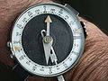 Soviet Army wrist compass with two (opposite) scales, 360 degrees clockwise and 6000 Soviet mil counterclockwise.


Use in artillery sights
[edit]Artillery uses angular measurement in gun laying, the azimuth between the gun and its target many kilometers away and the elevation angle of the barrel. This means that artillery uses mils to graduate indirect fire azimuth sights (called dial sights or panoramic telescopes), their associated instruments (directors or aiming circles), their elevation sights (clinometers or quadrants), together with their manual plotting devices, firing tables and fire control computers.
Artillery spotters typically use their calibrated binoculars to move fired projectiles' impact onto a target. Here they know the approximate range to the target and so can read off the angle (+ quick calculation) to give the left/right corrections in meters. A mil is a meter at a range of one thousand meters (for example, to move the impact of an artillery round 100 meters by a gun firing from 3 km away, it is necessary to shift the direction by 100/3 = 33.3 mils.)
Other scientific and technological uses
[edit]The milliradian (and other SI multiples) is also used in other fields of science and technology for describing small angles, i.e. measuring alignment,[12][13] collimation,[14] and beam divergence in optics,[15] and accelerometers and gyroscopes in inertial navigation systems.[16][17]
See also
[edit]- Scandinavian mile, a unit of length common in Norway and Sweden, but not Denmark, today standardised as 10 kilometers.
- Thousandth of an inch, an inch-based unit often called a thou or a mil.
- Circular mil, a unit of area, equal to the area of a circle with a diameter of one thousandth of an inch.
- Square mil, a unit of area, equal to the area of a square with sides of length of one thousandth of an inch.
Footnotes
[edit]- ^ Sweden (and Finland) have not been part of NATO nor the Warsaw Pact. However that Sweden has changed its map grid systems and angular measurement to those used by NATO, so the "streck" measurement unit is obsolete.[citation needed]
References
[edit]- ^ "How to use milliradian-adjustable scopes". Outdoor Hub. 14 July 2011.
- ^ Renaud, Hugues (31 May 2002). Dictionnaire historique de la Suisse. Fonds, AV Laussane.
Dapples: ... Charles-Marc (1837-1920), ingénieur, professeur à l'université de Lausanne, municipal à Lausanne, est l'inventeur de l'unité appelée "millième" pour mesurer les angles dans le tir d'artillerie. Une branche de la famille s'est fixée à Gênes à la fin du XVIIIe s.
- ^ "Calculation of approximation error for 0.1 mrad". Wolfram Alpha.
- ^ "Calculation of approximation error for 30 mrad". Wolfram Alpha.
- ^ "Calculation of approximation error for 300 mrad". Wolfram Alpha.
- ^ "Calculation of approximation error for 1′". Wolfram Alpha.
- ^ "Calculation of approximation error for 100′". Wolfram Alpha.
- ^ "Calculation of approximation error for 1000′". Wolfram Alpha.
- ^ "Divisions GB". Online Compass Museum. Compassipedia.
- ^ Taistelijan Opas 2013 (PDF) (in Finnish). Army Command (Finland). ISBN 978-951-25-2485-3. Archived (PDF) from the original on 5 May 2016. Retrieved 18 May 2019.
- ^ "Suunnistus: Piiru" (in Finnish). Archived from the original on 18 May 2019. Retrieved 18 May 2019.
- ^ "Optical Beam Alignment Meter". Opto-Mechanical Products Catalog. Light Test & Measurement Instruments. Vilnius, LT: Standa.
- ^ "The mirror alignment and control system for CT5" (PDF). The H.E.S.S. experiment. Geneva, CH: CERN.
- ^ "Focusing and Collimating". Newport. Technical Note.
Photonics solutions for extending the frontiers of science
- ^ "beam divergence". Encyclopedia of Laser Physics and Technology.
- ^ Groves, Paul D. (2013). Principles of GNSS, Inertial, and Multisensor Integrated Navigation Systems (Second ed.). ISBN 9781608070053.
- ^ Nebylov, Alexander V.; Watson, Joseph (2016). Aerospace Navigation Systems. John Wiley & Sons. ISBN 9781119163060.
External links
[edit]- "angles". convertworld.com.
- Simeone, Robert J. "Mils / MOA & the range estimation equations". scribd.com.
- "Compassipedia". The Online Compass Museum.
Milliradian
View on GrokipediaDefinition and Fundamentals
Mathematical Definition
The milliradian, denoted by the symbol mrad, is an SI derived unit of angular measurement defined as one-thousandth of a radian, or exactly radian.[6] This unit is dimensionless, consistent with the radian itself, which is the SI coherent unit for plane angle defined as the angle subtended at the center of a circle by an arc equal in length to the radius.[7] Approximately, one milliradian corresponds to . The radian measures angles such that a full circle corresponds to radians, leading to exactly milliradians in a complete revolution, or approximately 6283.185 milliradians.[7] Thus, there are 1000 milliradians per radian.[8] In geometry, the arc length subtended by an angle (in radians) on a circle of radius is given by the formula When is expressed in milliradians as , the formula becomes , providing a linear approximation that is particularly accurate for small angles where the milliradian's subtlety is advantageous.[7] The symbol "mil" is sometimes used informally but can be ambiguous, so mrad is preferred in precise mathematical contexts.[6]Relation to Degrees and Minutes of Arc
The milliradian (mrad) is defined as one-thousandth of a radian, and its relation to degrees follows directly from the radian-to-degree conversion, where exactly radians equal 180 degrees. Thus, 1 mrad = , while 1 degree mrad.[9][10] Minutes of arc (MOA), equivalent to one-sixtieth of a degree, provide another common angular unit for fine measurements. Accordingly, 1 mrad MOA, and 1 MOA mrad.[11][12] The following table summarizes conversions for select milliradian values to degrees and MOA, rounded to four decimal places for practical use:| Milliradians (mrad) | Degrees (°) | Minutes of Arc (MOA) |
|---|---|---|
| 1 | 0.0573 | 3.4377 |
| 10 | 0.57296 | 34.3775 |
| 100 | 5.7296 | 343.775 |
Mathematical Principles
Exact Angular Subtension
The angular subtension in milliradians refers to the angle subtended by a linear size at a distance , where quantifies the visual extent of as seen from the observer's position. This concept originates from the fundamental geometric relation for the arc length on a circle of radius , given exactly by , where is the central angle in radians. In the context of subtension, serves as the radius , and approximates the arc length for small angles, yielding with in radians.[15] Since a milliradian is defined as one-thousandth of a radian (), substituting into the arc length relation produces the precise subtension formula , where and are in the same units (e.g., meters). This equation directly translates the angular measurement into the corresponding linear dimension at distance , forming the basis for precise targeting and measurement in optics and ballistics.[16] For instance, at a distance of 1000 meters, a subtension of 1 milliradian corresponds to a linear size of meter, illustrating the metric convenience where 1 mrad subtends 1 meter at 1000 meters. This exact relation holds rigorously when radian (typically radian or about 5.7 degrees), as the arc length approximation aligns closely with the actual chord or tangent subtension in practical applications.[16]Small-Angle Approximation and Error Analysis
The small-angle approximation is essential for practical calculations involving milliradians, as it simplifies the relationship between angular measure and linear subtension. For small angles θ in radians, sin(θ) ≈ θ, with the relative error approximately θ²/6. This approximation is accurate for θ < 0.1 rad (100 mrad), where the relative error remains below 0.17%, enabling reliable use in fields like optics and surveying without significant loss of precision.[17] In angular subtension, the approximation yields the linear size w_approx = d · θ, where d is the distance, building on the basic subtension formula from exact principles. The exact linear subtension is w_exact = 2 d tan(θ/2), and the percentage error is 100 · (w_approx - w_exact)/w_exact. From the Taylor series expansion of the tangent function, this error approximates to - (θ²/12) · 100% (underestimation), or magnitude (θ²/12) · 100%.[18][19] The following table illustrates the percentage error in subtension for representative small angles:| Angle (mrad) | θ (rad) | Percentage Error (%) |
|---|---|---|
| 10 | 0.01 | <0.01 |
| 100 | 0.1 | ≈0.08 |
Applications in Shooting and Optics
Sight Adjustment and Click Values
In firearm optics, milliradians (mrad) provide a standardized metric for mechanical sight adjustments, allowing shooters to precisely calibrate elevation and windage dials on rifle scopes to compensate for bullet drop, wind drift, and other ballistic factors. These adjustments are typically made via tactile clicks on the scope's turrets, where each click corresponds to a small angular increment in milliradians, enabling fine-tuned corrections without relying on visual reticle measurements.[20][21] The most common click value in precision rifle scopes is 0.1 mrad per click, often referred to as "one centimeter clicks" because 0.1 mrad subtends approximately 1 cm at 100 meters. This increment is standard in many tactical and long-range optics from manufacturers like Vortex and Leupold, facilitating accurate dialing for distances up to 1,000 meters or beyond. For match-grade or benchrest applications requiring even finer precision, click values as small as 0.05 mrad are available, allowing adjustments of about 5 mm at 100 meters.[22][20][21] The adjustment process involves rotating the elevation or windage turrets to shift the point of impact by a linear distance determined by the angular value and target range. For a given click value (in mrad) and distance (in meters), the point of impact moves by meters, assuming small-angle approximation holds. Multiple clicks accumulate additively; for instance, 10 clicks at 0.1 mrad each equal a 1 mrad total adjustment, shifting the point of impact by 1 meter at 1,000 meters. This metric system aligns well with ballistic calculators and range finders used in precision shooting.[23] Most modern rifle scopes offer a total adjustment range of 20-40 mrad or more for elevation and windage combined, providing sufficient travel for zeroing at typical battle rifle distances (e.g., 100-300 meters) and dialing to extreme long ranges (e.g., 1,000+ meters). To optimize usable elevation, scopes often incorporate a base tilt of 5-10 mrad in the mounting system, which pre-angles the optic upward and preserves downward adjustment for close-range zeroing while maximizing upward travel for distant targets. High-end models, such as the Vortex Razor HD Gen III, can exceed 36 mrad in total elevation adjustment, supporting extended-range applications.[24][25]Reticle Subtensions and Range Estimation
In optical sights used for shooting, reticles marked in milliradians enable precise angular measurements of targets, facilitating range estimation without additional equipment. Common types include the mil-dot reticle, which features dots spaced at 1 milliradian (mrad) intervals between centers, allowing shooters to gauge target subtensions visually.[26] Other variants, such as the Tactical Milling Reticle (TMR) and Horus reticles (e.g., H27), incorporate hash marks at intervals of 1 mrad or finer subdivisions like 0.2 or 0.5 mrad for enhanced accuracy in ranging and holdover calculations.[27] The fundamental formula for range estimation using these reticles derives from the milliradian's definition, where 1 mrad subtends approximately 1 meter at 1000 meters. It is expressed as: This equation assumes metric units for both target dimension and distance, providing a direct proportional relationship between the observed angular size and actual range.[28][26] For practical application, consider a human target of 1.7 meters in height subtending 5 mrads through the reticle; the estimated range is meters. Similarly, a vehicle with a 2.5-meter width spanning 2.5 mrads yields meters. These examples illustrate how shooters align the reticle's marks with known target features to read the mrad value quickly.[29][28] When targets are measured in non-metric units, such as inches or yards, conversions to meters are necessary before applying the formula to maintain accuracy; for instance, a 72-inch target height (approximately 1.83 meters) subtending 3 mrads estimates to about 610 meters. This metric foundation aligns with international standards in military and precision shooting contexts.[26][27]Shot Group Analysis
In shot group analysis, milliradians provide a distance-independent metric for quantifying the angular dispersion of projectile impacts, enabling consistent evaluation of firearm and ammunition precision. The primary measure is the extreme spread, defined as the maximum center-to-center distance between any two shots in a group, converted to angular units. This approach captures the overall size of the shot pattern as an angle subtended at the firearm, independent of target distance, which is particularly useful for comparing performance across varying ranges.[30] To calculate the extreme spread in milliradians, the linear group diameter (in millimeters) is divided by the shooting distance (in meters), yielding , where is the angular size in mrad. For example, a 3-shot group with a 75 mm center-to-center extreme spread at 100 meters equates to 0.75 mrad, illustrating a sub-mrad precision level suitable for long-range applications. This formula derives from the definition of a milliradian as the angle subtending 1 mm at 1 meter, scaled linearly.[31][32] For more statistically robust assessments, mean radius—the average radial distance of all shots from the group centroid—and circular error probable (CEP)—the radius of a circle centered on the centroid enclosing 50% of the shots—are commonly expressed in mrad. These metrics better account for the distribution of impacts compared to extreme spread alone, allowing shooters to evaluate and compare ammunition consistency or rifle accuracy with reduced sensitivity to outliers; for instance, a mean radius of 0.5 mrad indicates tighter central tendency than an extreme spread of 1 mrad. Such angular statistics facilitate standardized testing protocols in precision rifle disciplines.[33] Milliradians confer advantages over minutes of angle (MOA) in shot group analysis due to their decimal-based structure, which aligns seamlessly with metric measurements prevalent in modern firearms and ballistics software. This simplicity enables quicker mental arithmetic and data logging—e.g., a 0.75 mrad group is more intuitive than its approximate 2.58 MOA equivalent—enhancing efficiency for metric-oriented shooters without the need for fractional adjustments common in MOA systems.[34]Applications in Artillery and Cartography
Artillery Fire Control
In artillery fire control, milliradians, commonly referred to as mils in military contexts, are essential for precise angular measurements in directing and adjusting indirect fire. The fire direction center (FDC) computes and issues firing data, including quadrant elevation (QE)—the vertical angle from the base of the trajectory to the bore axis—and deflection, the horizontal angle from the line of sight to the tube axis, both expressed in mils to the nearest whole unit. These measurements enable accurate ballistic solutions for howitzers and guns, with QE typically ranging from minimum values like 101 mils for safe clearance to over 800 mils for high-angle fire, while deflections are adjusted for factors such as drift and crosswinds using graphical firing tables (GFTs). Sights on artillery pieces, such as the M1A3 gunner's quadrant, measure elevations to 0.1 mil precision for setting the barrel, ensuring alignment with FDC commands.[35][36] Fire adjustments rely on spotting rounds to refine aim, with corrections issued in fire commands using mils for angular shifts. For instance, an observer might report a deviation, leading to commands like "LEFT 2 MILS" for deflection or "ADD 3 MILS" to increase QE, converting linear deviations (e.g., 40 meters left at 15,000 meters range) via the mil relation formula to angular values of approximately 2.67 mils. These iterative corrections, starting with an initial spotting round and progressing to "fire for effect," minimize probable errors in impact, such as 4 meters in range per mil at 6,000 meters with charge 5 green bag. The FDC verifies all commands for safety, ensuring adjustments stay within tabular firing limits and minimum QE thresholds to avoid dangers like crest clearance issues.[35][36] Modern digital FDCs, such as the Advanced Field Artillery Tactical Data System (AFATDS), automate these processes using mils for computations integrated with GPS for precise positioning and targeting. AFATDS processes fire requests, generates mil-based aiming points, and supports joint operations by linking observer data with GPS-derived coordinates, allowing rapid adjustments across ranges exceeding 30 kilometers and angular spans up to 100+ mils for full mission coverage. This enhances accuracy and speed compared to manual methods, incorporating real-time meteorological and terrain data.[37][38] Standardization in NATO artillery employs 6,400 mils per full circle for simplicity in quadrant divisions (1,600 mils per quadrant), differing from the true milliradian approximation of 6,283 mils derived from 1/1,000 radian, which introduces a minor scaling factor of about 1.018 in conversions but ensures interoperability in fire control. This 6,400-mil system, rooted in practical gunnery needs, is codified in U.S. and allied field manuals for consistent deflection and elevation commands.[36][35]Map Grids and Compass Bearings
In military topographic maps and navigation, the milliradian (mil) provides a practical angular unit for estimating distances and plotting positions, leveraging the approximation that 1 mil subtends approximately 1 meter of arc length at a range of 1 kilometer. This relation, derived from the small-angle approximation where the tangent of the angle equals the opposite side over the adjacent side (tan θ ≈ θ for small θ in radians), allows personnel to quickly convert angular measurements to linear distances without complex calculations. For instance, if an observed feature subtends 2 mils and its actual width is known to be 10 meters, the range can be estimated as (10 meters × 1000) / 2 mils = 5 kilometers. This principle is integral to the U.S. Army's range determination procedures in field manuals.[39] Military map grids, such as those in the Military Grid Reference System (MGRS), incorporate mil-based increments for precision, often dividing grid squares into 10-mil intervals to facilitate accurate positioning and azimuth plotting. These grids align with the 1 mil ≈ 1 meter per kilometer scale, enabling surveyors and artillery spotters to measure deviations or offsets directly in mils relative to grid lines spaced at 1-kilometer intervals. On a standard 1:50,000 scale map, where 1 millimeter on the map represents 50 meters on the ground, this translates to 1 mil corresponding to 50 meters at a 50-kilometer range, as the linear subtension scales proportionally with distance (subtended distance = range × θ, with θ in radians). This aids in estimating target distances by comparing known map features to observed angular sizes.[39] Compasses used in military navigation feature bezels graduated in mils, typically dividing the full 360-degree circle into 6400 mils for finer resolution than degrees, which suits bearing deviations and azimuth adjustments in artillery and surveying. Azimuths are plotted using mil-scaled protractors overlaid on maps, where directions are measured clockwise from grid north: 0/6400 mils to north, 1600 mils to east, 3200 mils to south, and 4800 mils to west. This system allows for precise deviation calculations, such as adjusting a magnetic bearing to grid azimuth by the grid-magnetic angle in mils. For example, to plot an azimuth of 3200 mils (due south) from a known grid coordinate, the protractor aligns the mil scale with the grid line, marking the intersection for the target point.[40] To integrate milliradian measurements with traditional systems, conversions are essential. The true milliradian (1/1000 radian) equates to approximately 0.0573 degrees, while the NATO military mil (1/6400 of a circle) is about 0.05625 degrees; however, in practice, milliradians are often approximated closely to military mils for compatibility. Compass points, dividing the circle into 32 equal parts of 11.25 degrees each, can be converted similarly, with 1 milliradian spanning roughly 0.0051 compass points (11.25° / 0.0573° per mrad). The table below provides key conversions for common values:| Milliradians (mrad) | Degrees (°) | NATO Mils (approx.) | Compass Points (approx.) |
|---|---|---|---|
| 10 | 0.573 | 10.2 | 0.051 |
| 100 | 5.73 | 102 | 0.51 |
| 1000 | 57.3 | 1019 | 5.1 |
| 6283 (full circle) | 360 | 6400 | 32 |