Hubbry Logo
search
logo
2054743

Circularly disposed antenna array

logo
Community Hub0 Subscribers
Read side by side
from Wikipedia
Direction-finding system Galeta Island, Panama

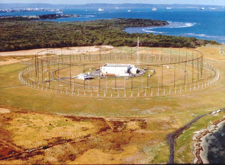
A circularly disposed antenna array (CDAA), sometimes referred to as a circularly disposed dipole array (CDDA) or a wullenweber,[1] is a large circular antenna array used for radio direction finding. They are used by military and government agencies to triangulate radio signals for radio navigation, intelligence gathering, search and rescue, and enforcement of broadcasting laws. Because their huge circular reflecting screens look like circular fences, some antennas have been colloquially referred to as "elephant cages". The term "wullenweber" was the World War II German cover term used to identify their secret CDAA research and development program; its name is unrelated to any person involved in the program.

Many such CDAA systems are used by many nations, such as the former Soviet Union and modern-day Russia, Germany, the United Kingdom, and the United States.

History

[edit]

Origin in World War II Germany

[edit]

CDAA technology was developed by the German navy communication research command, Nachrichtenmittelversuchskommando (NVK) and Telefunken, working on the Wullenweber during the early years of World War II. The inventor was NVK group leader Dr. Hans Rindfleisch, who worked after the war as a Technical Director for the northern Germany official broadcast (Norddeutscher Rundfunk (NDR)). Technical team leaders were Dr. Joachim Pietzner, Dr. Hans Schellhoss, and Dr. Maximilian Wächtler. The last was a founder of Plath GmbH in 1954 and later a consultant to both Plath and Telefunken.

The first Wullenwever was built during the war at Skibsby, north-east of the city of Hjørring (in German: Hjörring), Denmark (57°29′10″N 10°00′38″E / 57.48611°N 10.01056°E / 57.48611; 10.01056). It used 40 vertical radiator elements, placed on the arc of a circle with a diameter of 120 metres (390 ft). In an inner circle, 40 reflecting elements were placed behind the radiator elements, suspended from a structure of circular wooden support poles with a diameter of 112.5 meters. To more easily obtain true geographic bearings, the north and south elements were placed exactly on the north–south meridian.

Post-war development

[edit]

Although Pietzner, Schellhoss, and Wächtler retired in West Germany, some of their second-echelon technicians were taken to the USSR after the war. At least 30 Krug (Russian for circle) arrays were installed all over the Soviet Union and allied countries in the 1950s, well before the U.S. military became interested and developed their CDAAs. Several Krugs were installed in pairs less than 10 kilometers from each other, apparently for radio navigation purposes. At least four Krugs were installed near Moscow; just to the north, east and south (55°27′51″N 37°22′11″E / 55.46408°N 37.3698°E / 55.46408; 37.3698) of the city. The Krugs were used to track the early Sputnik satellites, using their 10 and 20 MHz beacons, and were instrumental in locating re-entry vehicles. The Soviet Krug arrays also use the 40-element CDAA configuration. [1]

The array in Skibsby was extensively studied by the British and then destroyed following the war in accordance with the Geneva Convention. Dr. Wächtler arranged to have a second array built, at Telefunken expense, at Langenargen/Bodensee, for further experimentation after the war. In the years following the war, the U.S. disassembled the Langenargen / Bodensee array and brought it back to the U.S., where it became known as the "Wullenweber" array.

One of the German antenna researchers, Dr. Rolf Wundt, was one of hundreds of German scientists taken to the U.S. by the Army after the war under Operation Paperclip. He arrived in New York in March 1947 on the same ship as Wernher von Braun and his wife and parents. He was first employed by the U.S. Air Force and then GT&E Sylvania Electronics Systems on CDAA and other antenna projects.

Professor Edgar Hayden, then a young engineer in the University of Illinois Radio Direction Finding Research Group, led the reassembly of the Wullenweber, studied the design and performance of HF/DF arrays and researched the physics of HF/DF under contract to the U.S. Navy from 1947 through 1960.

Hayden led the design and development of a large circularly disposed array at the university's Bondville Road Field Station, a few miles southwest of Bondville, IL. The array consisted of a ring of 120 vertical monopoles covering 2–20 MHz. Tall wood poles supported a 1,000-foot  diameter (300 m) circular screen of vertical wires located within the ring of monopoles. His research is still used today to guide the design and site selection of HF/DF arrays. Records of his research are available in the university's archives. Hayden was later employed by Southwest Research Institute where he continued to contribute to HF direction finding technology.

The 1960s–1970s construction boom and subsequent demolition

[edit]

In 1959, the U.S. Navy contracted with ITT Federal Systems to deploy a worldwide network of AN/FRD-10 HF/DF arrays based on lessons learned from the Bondville experimental array.

CDAA at US Navy Sobe Communications base, Yomitan, Okinawa, Japan

The FRD-10 at NSGA Hanza, Okinawa was the first installed, in 1962, followed by eleven additional arrays, with the last completed in 1964 at NRRF Imperial Beach, CA. (Silver Strand) which was demolished in 2014. Due to their immense size, the location of the Bondville array (40°02′58″N 88°22′51″W / 40.0494°N 88.3807°W / 40.0494; -88.3807) and the other post-war antenna arrays are clearly visible in high-resolution aerial photography now available on the internet.

Also in 1959, a contract to build a larger CDAA — the AN/FLR-9 antenna receiving system — was awarded by the U.S. Air Force to GT&E Sylvania Electronics Systems (now General Dynamics Mission Systems).

The first FLR-9 was installed at RAF Chicksands (52°02′39″N 0°23′21″W / 52.0443°N 0.389182°W / 52.0443; -0.389182) in the United Kingdom in 1962. The second FLR-9 was installed at San Vito dei Normanni Air Station (40°38′49″N 17°50′20″E / 40.64700°N 17.83900°E / 40.64700; 17.83900), Italy also in 1962. Following base closures, the arrays at Chicksands and San Vito were dismantled in 1996 and 1993, respectively.

FLR-9 circularly disposed antenna array at Elmendorf Air Force Base, Alaska, USA, completed in 1966.

A second contract was awarded to Sylvania to install AN/FLR-9 systems at Misawa AB, Japan; Clark AB, Philippine Islands; Pakistan (never built); Elmendorf AFB, Alaska; and Karamürsel AS, Turkey. The last two were completed in 1966. The Karamürsel AS was closed and array was dismantled in 1977 in retribution for the suspension of U.S. military aid to Turkey. The Clark AB array was decommissioned after the Mt. Pinatubo volcano eruption in 1991. It was later converted into an outdoor amphitheater which is part of the Nayong Pilipino Clark theme park. Demolition of the Misawa FLR-9 began in October 2014.

A pair of FRD-10s not equipped for HF/DF were installed in 1969 at NAVRADSTA(R) Sugar Grove, WV (38°30′46″N 79°16′44″W / 38.5129°N 79.2790°W / 38.5129; -79.2790), for naval HF communications, replacing the NSS receiver site at the Naval Communications Station in Cheltenham, Maryland.

An overhead view of Elmendorf AFB, Alaska, in late 2002. The antenna array is the large circle in the forested area, in the upper left, comparable in size to the adjacent airstrip.

The Elmendorf array was decommissioned in May 2016[2][3] due to its age and unavailable repair parts.

The U.S. Army awarded a contract in 1968 to F&M Systems to build AN/FLR-9 systems for USASA Field Station Augsburg, Germany, and Ramasun Station in Udon Thani, Thailand (17°17′31″N 102°52′06″E / 17.2919°N 102.8682°E / 17.2919; 102.8682). Both were installed in 1970.[4] The Ramasun Station array was dismantled in 1975 following base closure.

During the 1970s, the Japanese government installed two large antenna arrays, similar to the FRD-10, at Chitose and Miho.

Surviving arrays and replacements

[edit]

The last two FRD-10 HF/DF arrays were installed in 1971 for the Canadian Forces in Gander, Newfoundland (48°57′04″N 54°31′31″W / 48.9511°N 54.5252°W / 48.9511; -54.5252) and Masset, British Columbia (54°01′44″N 132°03′55″W / 54.0288°N 132.0654°W / 54.0288; -132.0654). After the Hanza array was decommissioned in 2006, the Canadian Armed Forces became the operators of one of the last two existing FRD-10 arrays.

Later in the 1970s, Plessey (now Roke Manor Research Limited) of the United Kingdom developed the smaller, more economical Pusher CDAA array. At least 25 Pusher CDAAs were installed in many countries around the world. Several Pusher arrays were installed in U.S. military facilities, where the array is known as the AN/FRD-13.

In 1998 the Augsburg array (48°27′04″N 10°51′46″E / 48.45121°N 10.86275°E / 48.45121; 10.86275)—located in Gablingen, a town in the north of Augsburg—was turned over to the Bundesnachrichtendienst. Technology enthusiasts, reporters, and even local politicians are still not admitted to the complex and there are few official statements about its purpose. The area was greyed out in the map layers of Google Maps[5] and Bing Maps. Therefore, it is believed to be still in service being used by BND and NSA as part of a larger complex of combined informational technology.

Post–Cold War arrays

[edit]
Satellite imagery of the 0.8 km radius Chernyakhovsk CDAA

As of November 2020 the Strategic Reconnaissance Command of the German Armed Forces operates as one of its three stationary Sigint battalions a 410 metres (1,350 ft) wide circularly disposed array in Bramstedtlund. It was inaugurated in 1995 with construction started in 1989.[6]

In August 2025 media reported on Chernyakhovsk CDAA, an almost finished, 1,600 m wide circularly disposed array circa 5 km southeast of the Chernyakhovsk airbase in the Kaliningrad enclave.[7][8][9]

See also

[edit]

References

[edit]
[edit]
Revisions and contributorsEdit on WikipediaRead on Wikipedia
from Grokipedia
A circularly disposed antenna array (CDAA) is a high-frequency radio direction-finding system comprising multiple omnidirectional antennas, such as vertical monopoles, arranged symmetrically in concentric rings around a circular reflector to achieve precise signal bearing measurements across 360 degrees without mechanical movement.[1] Originating from the German Navy's Wullenweber array during World War II, the design was refined in the 1950s for signals intelligence applications, offering superior accuracy and gain compared to earlier goniometers due to electronic beam steering via phase comparisons among elements.[2][3] U.S. military implementations, including the AN/FRD-10 and AN/FLR-9 systems, featured large-scale arrays—often spanning hundreds of feet—with up to 120 active elements selectable for optimal performance in triangulating distant emitters for intelligence gathering and navigation.[1][4] These arrays excel in environments requiring rapid, ambiguity-free direction finding, leveraging the circular geometry for inherent calibration and minimal multipath errors, though their massive footprints and vulnerability to electronic countermeasures limited deployments primarily to fixed, secure sites.[2][1]

Overview

Definition and Principles

A circularly disposed antenna array (CDAA) consists of numerous vertically polarized monopole antennas arranged symmetrically in one or more concentric circles surrounding a central goniometer or processing unit, often backed by a circular reflective screen to enhance directivity.[1] This geometry enables omnidirectional reception across the full 360-degree azimuth without requiring mechanical rotation of the array.[1] The system operates primarily in the high-frequency (HF) band, from approximately 2 to 30 MHz, where ionospheric propagation supports long-range signal detection.[1] The core operating principle relies on electronic beamforming through selective phasing of signals received by individual elements.[1] A goniometer or phase-comparison mechanism combines outputs from subsets of antennas to form directive beams that can be rapidly scanned electronically, identifying the direction of signal arrival by detecting the beam position yielding maximum amplitude.[1] This method exploits phase differences among elements due to the angle of incidence, yielding precise bearing estimates for incoming HF transmissions.[1] The array's high sensitivity to weak or transient signals stems from its large effective aperture and coherent summation of element outputs, which provides array gain via constructive interference in the steered direction.[1] Circular symmetry ensures uniform response characteristics across all azimuths, minimizing pattern distortions that could arise in linear or irregular arrays, thereby supporting reliable direction finding under varying propagation conditions.[1]

Historical Context and Nomenclature

The circularly disposed antenna array (CDAA), also designated as the circularly disposed dipole array (CDDA), emerged from early 20th-century advancements in radio direction-finding technologies rooted in high-frequency signal interception needs.[2] Commonly referred to as the Wullenweber array in recognition of its German developmental origins—named after a code designation employed by the German Navy—these systems feature a radial configuration of antenna elements arranged in a large circle, often augmented by a polygonal reflector screen.[5] Informally dubbed "elephant cages" owing to the massive, wire-mesh reflector structures resembling oversized enclosures, the nomenclature reflects both technical precision and the imposing scale of operational installations, typically spanning diameters of 100 to 400 meters.[6] German naval research during the interwar and early World War II periods prioritized such arrays for signals intelligence (SIGINT), enabling precise triangulation of high-frequency transmissions amid the electromagnetic challenges of maritime environments.[7] Dr. Hans Rindfleisch, leading efforts within the Navy's Nachrichtenversuchs Kommando (NVK), advanced the design to support interception of Allied communications, providing a causal advantage in operational awareness through superior bearing resolution over linear or Adcock arrays.[5] This configuration's empirical validation in wartime applications demonstrated direction-finding accuracies of 1 to 2 degrees under favorable propagation conditions, surpassing prior methods limited by multipath interference and mechanical scanning constraints.[2][8]

Technical Design

Core Components

A circularly disposed antenna array (CDAA) comprises symmetrically arranged receiving elements within a passive reflector screen, with electronic support structures for signal handling. The receiving elements consist of vertical sleeve monopoles for lower frequency bands and dipoles for higher bands, typically numbering 40 to 120 per ring in configurations like the AN/FRD-10, which operates from 1.5 to 30 MHz across three concentric rings: 48 outer monopoles for 1.5–6 MHz, 96 center monopoles for 6–18 MHz, and 48 inner dipoles for 18–30 MHz.[9][1] The reflector screen, functioning as a passive parasitic structure, uses 1056 grounded vertical steel wires per lower-band ring (120 feet high) and 44 horizontal galvanized steel wires for the high band, supported by poles to form a near-circular or polygonal enclosure enhancing forward sensitivity; diameters reach approximately 260 meters for outer rings in large installations.[9][10] Central infrastructure includes a goniometer for phase sampling from multiple element inputs, coaxial transmission lines connecting antennas to combiners, and analog units like CU-2053 power dividers (4:32 configuration with ≥30 dB isolation) for signal summation prior to processing.[9][1] Materials emphasize durability with steel masts and wires for reflectors and supports, fiberglass-polyester for monopole weather caps, and stainless steel grid mats for ground screens beneath lower-band elements.[9]

Configuration and Geometry

The configuration of a circularly disposed antenna array (CDAA) centers on vertically polarized monopole or dipole elements arranged in one or more concentric rings along a circular perimeter, enabling omnidirectional reception and exploitation of azimuthal phase gradients for direction finding. This geometry leverages the symmetry of a circle to ensure uniform sensitivity across 360 degrees, with elements spaced at equal angular intervals to approximate a continuous aperture and facilitate modal decomposition of incoming wavefronts.[11] The rationale for the circular layout stems from first-principles electromagnetics: for a plane wave arriving from azimuth ϕ\phi, the phase at the kk-th element at angle ϕk\phi_k and radius rr is Δϕk=(2πr/λ)cos(ϕϕk)\Delta\phi_k = (2\pi r / \lambda) \cos(\phi - \phi_k), allowing the array manifold to be expressed as a Fourier series in azimuthal harmonics, which inherently supports unambiguous estimation of ϕ\phi without the endfire ambiguities common in linear arrays.[12] Uniform angular spacing, typically on the order of 3 degrees, minimizes grating lobes and sidelobe levels under uniform or tapered excitation, as derived from array factor analysis where the pattern AF(ψ)=ejNψ/2sin(Nψ/2)/sin(ψ/2)AF(\psi) = \sum e^{j N \psi / 2} \sin(N \psi / 2) / \sin(\psi / 2) (with ψ\psi incorporating circular geometry) achieves low sidelobes via Tchebycheff optimization for specified ripple.[11] Key geometrical parameters include the number of elements, ring radii, and reflector positioning, tailored to high-frequency (HF) operation spanning 2–30 MHz. High-resolution systems commonly feature 120 elements in the outer ring, providing 3-degree spacing for fine angular discrimination, as implemented in designs like the AN/FRD-10 where the outer ring supports the 9–30 MHz band.[1] [13] Multiple rings address bandwidth: inner rings operate at lower frequencies with radii around 0.4–0.5 wavelengths ([14]) at the band edge to maintain electrical aperture for phase sensitivity, while outer rings extend to 0.9–1 [14] for higher bands, ensuring the effective diameter D2rD \approx 2r yields resolution Δϕλ/D\Delta\phi \approx \lambda / D radians (approximately 1–2 degrees for D100D \sim 100 m at 10 MHz).[15] Inter-element spacing along the arc is held near 0.4λ\lambda to avoid mutual coupling artifacts that elevate sidelobes beyond -20 dB, with empirical pattern synthesis confirming optimal gain-diameter relations via charts correlating element count, frequency, and array size for peak directivity.[2] A critical feature is the reflector screen—a cylindrical or polygonal wire mesh positioned radially inward, with elements offset approximately λ/4\lambda/4 in front to invoke image theory for enhanced forward gain and ground-plane simulation, reducing backward radiation and low-angle multipath.[2] Slight tilt of the reflector (e.g., 5–10 degrees) optimizes the virtual image height for skywave paths, where ionospheric refraction introduces elevation angles of 10–30 degrees; this causal adjustment minimizes phase errors from ground reflections, as the effective height heff=2dsinαh_{eff} = 2 d \sin\alpha (with dd the element-reflector distance and α\alpha tilt) aligns with propagation geometry. Compared to linear arrays, the circular form empirically exhibits lower bearing errors (e.g., <1 degree RMS in tests) under multipath due to azimuthal averaging, which dilutes asymmetric scattering not aligned with the boresight.[11] These parameters derive from causal constraints of HF propagation, prioritizing large apertures (diameters 100–400 feet) to capture differential path lengths amid refractive index gradients.[1]

Signal Processing and Direction Finding

Signal processing in circularly disposed antenna arrays (CDAAs) for direction finding primarily employs phase interferometry and amplitude comparison techniques applied to signals received across the array's elements. Phase interferometry measures the differential phase shifts between pairs or subsets of antennas, exploiting the array's large circular baseline to resolve the angle of arrival (AoA) with high precision, typically achieving bearing resolutions of 0.5 to 1 degree under favorable ionospheric conditions.[16] Amplitude comparison, often implemented via monopulse methods, forms sum and difference patterns from opposing or adjacent elements to generate error signals proportional to the signal's offset from boresight, enabling rapid bearing extraction without mechanical scanning.[17] These approaches leverage the array's omnidirectional coverage and space diversity to mitigate multipath fading from ionospheric propagation, forming virtual lobes that electronically steer sensitivity toward the incoming wavefront.[2] Early WWII-era CDAAs, such as Wullenweber designs, utilized analog goniometers to process signals from a fixed arc of elements, electrically simulating a rotating directional antenna through inductive coupling and phase summation for bearing indication.[18] This method provided instantaneous direction finding via Watson-Watt sum-difference principles, avoiding physical rotation while maintaining analog simplicity for high-frequency (HF) signals.[2] By the post-1960s period, hybrid systems emerged, integrating analog preselectors for frequency agility and initial signal conditioning with digital correlators for enhanced AoA estimation, reducing errors from array imperfections and improving automation in platforms like the AN/FRD-10.[1] Declassified military evaluations confirm robust performance, with intercept probabilities exceeding 90% for pulsed HF signals under 1 second duration, attributed to the array's diversity gain against short-term fading.[2] These capabilities stem from the physics of plane-wave arrival at the circular geometry, where baseline length inversely scales angular ambiguity, though practical limits arise from ionospheric tilt and noise, necessitating calibration for sub-degree accuracy.[16]

History

World War II Origins

The circularly disposed antenna array, known during World War II as the Wullenweber array, originated in German naval research for high-frequency direction finding (HFDF) to support Kriegsmarine operations in the Battle of the Atlantic. Developed under the direction of Dr. Hans Wullenweber in the late 1930s and early 1940s, the system addressed limitations of earlier linear arrays like the Adcock design, which struggled with rapid signal interception and precision in noisy maritime environments.[7][2] The Wullenweber configuration featured a circular ring of vertical dipole elements—typically 32 to 120 in number, spaced along a perimeter up to 120 meters in diameter—fed by a rotating goniometer for electronic beam steering, enabling ambidextrous reception and superior ambiguity resolution over traditional setups.[2] First operational deployments occurred around 1942, with prototype arrays constructed at coastal sites to monitor Allied convoy radio traffic on HF bands between 3 and 30 MHz. These installations, such as early test beds in northern Europe, provided the Kriegsmarine with bearing accuracies of 1-2 degrees under optimal conditions, far outperforming manual loop antennas or fixed Adcock systems in capturing brief, low-power transmissions from ships.[5] By integrating with centralized plotting rooms at facilities like B-Dienst headquarters, the arrays facilitated triangulation of convoy positions across multiple stations, directly informing U-boat wolfpack intercepts; for instance, precise fixes on HX and SC convoy signals contributed to sinkings exceeding 100 merchant vessels in mid-1943 alone, as validated by post-war analyses of German naval records.[19] Empirical advantages stemmed from the array's geometry, which minimized ground wave interference and supported simultaneous multi-beam scanning, allowing detection of pulsed or encrypted signals in under 10 seconds—critical for evading Allied high-frequency direction finding countermeasures like the "Huff-Duff" systems. German reports noted intercept probabilities over 90% for signals as short as 0.5 seconds, compared to 50-60% for Adcock arrays, enhancing tactical responsiveness without relying on vulnerable mobile units.[2] Despite resource constraints, at least five major Wullenweber sites were active by 1944, underscoring their role in sustaining U-boat effectiveness until Allied air superiority and code-breaking overwhelmed these capabilities.[5]

Post-War Development in the United States

Following World War II, the United States examined captured German Wullenweber circularly disposed antenna arrays (CDAAs), including a dismantled installation from Langenargen, Germany, which was analyzed at the University of Illinois to understand its signal intelligence (SIGINT) applications.[19] This reverse-engineering effort informed early American prototypes, as the German designs demonstrated superior direction-finding capabilities compared to existing Allied systems.[19] In the early 1950s, the Naval Research Laboratory (NRL) began refining CDAA technology, starting with a linear wide-aperture antenna tested in 1952 at Fox Ferry, Maryland.[19] By 1957, NRL constructed a 400-foot diameter circular prototype at Hybla Valley, Virginia, which successfully tracked the Sputnik I satellite launch, validating its high-frequency performance.[19] The Naval Security Group (NSG) initiated dedicated R&D on CDAAs in 1956, focusing on automation to surpass the manual switching limitations of the original German versions.[3] These advancements culminated in the standardization of the AN/FRD-10 by 1960, incorporating retrospective direction-finding techniques developed under Project Boresight alongside related systems like the AN/FLR-7.[19] Early evaluations revealed the AN/FRD-10 provided approximately four times the signal gain and accuracy (better than 0.5 degrees) of prior direction finders such as the AN/GRD-6, along with enhanced noise filtering, marking a substantial improvement in sensitivity over loop-based antennas.[19]

Cold War Proliferation and Peak Usage

During the 1960s, the United States Navy rapidly expanded its signals intelligence capabilities by constructing 14 AN/FRD-10 circularly disposed antenna arrays (CDAAs) worldwide as part of the Naval Security Group's Classic Bullseye high-frequency direction-finding network.[5] [20] These installations, including key sites at Sugar Grove, West Virginia, and Misawa Air Base, Japan, were designed to provide precise bearing data on Soviet high-frequency (HF) communications, enabling triangulation across multiple stations for location accuracy within degrees.[21] By 1966, 13 such sites operated across the U.S., its territories, and foreign countries, forming a global net critical to monitoring adversarial radio traffic.[22] This proliferation peaked in the 1970s, with the AN/FRD-10 arrays supporting real-time direction finding that fed into broader intelligence analysis for strategic deterrence against Soviet threats.[5] Each array required significant resources, with construction costs estimated between $800,000 and $900,000 per unit, reflecting the scale of the octagonal structures spanning hundreds of meters and incorporating central operations buildings.[5] The systems' deployment underscored the U.S. emphasis on HF spectrum dominance, where declassified accounts highlight their role in locating emitters amid dense Soviet signal environments.[22] Allied nations within the UKUSA Agreement—encompassing the United Kingdom, Australia, Canada, and others—adopted comparable CDAA technologies to enhance collective SIGINT sharing.[23] Canada, for instance, erected two AN/FRD-10 equivalents at Gander, Newfoundland, and Masset, British Columbia, integrating into the allied network for hemispheric coverage.[24] This cooperative expansion amplified the arrays' effectiveness, allowing synchronized fixes on HF transmissions that informed assessments of Soviet military posture, including naval and air force activities, thereby bolstering NATO and Five Eyes deterrence strategies.[25]

Post-Cold War Decline and Demolitions

Following the end of the Cold War and the dissolution of the Soviet Union in 1991, the operational demands for large-scale high-frequency direction-finding networks subsided, prompting widespread decommissioning of circularly disposed antenna arrays (CDAAs). The U.S. Navy's AN/FRD-10 systems, comprising 14 primary installations erected in the early 1960s as part of the Classic Bullseye program, exemplified this trend.[20] By the mid-1990s, initial shutdowns occurred amid budget reallocations, with the majority dismantled through the 1990s and into the early 2000s as maintenance burdens outweighed strategic value.[8] Obsolescence stemmed primarily from technological advancements in digital signal processing (DSP), which facilitated compact phased-array alternatives capable of matching or surpassing CDAA performance in bearing accuracy and signal sensitivity. These newer configurations achieved substantial footprint reductions—often halving the physical scale of legacy systems—while leveraging electronic beam steering to eliminate the need for massive mechanical structures like the 120-element high-band rings and extensive ground planes of AN/FRD-10 arrays.[8] High upkeep demands, including corrosion repair on elevated antenna cages spanning hundreds of meters and periodic recalibration of analog goniometers, further eroded cost-effectiveness, as empirical site data revealed diminishing returns against modern baselines.[26] Select U.S. sites persisted into the 2010s for niche legacy intercept roles, such as monitoring residual HF emitters, before final razings; for instance, the Imperial Beach facility in California was decommissioned by the early 2000s, and Hawaii's NCTAMS array faced demolition plans by 2006.[27] By 2015, no operational U.S. Navy AN/FRD-10 installations remained, marking the effective end of widespread CDAA reliance in American signals intelligence infrastructure.[28]

Applications

Military Signals Intelligence

Circularly disposed antenna arrays (CDAAs) served as critical assets in military signals intelligence (SIGINT), particularly for high-frequency (HF) direction finding to geolocate adversarial radio emitters. These systems provided lines of bearing on intercepted signals from aircraft, ships, and ground stations, facilitating triangulation when data from multiple sites were correlated to determine precise transmitter positions.[10] The U.S. Navy's AN/FRD-10 variant, deployed at 14 global locations during the Cold War, exemplified this capability, supporting both communications intelligence (COMINT) collection and emitter location for operational targeting.[19] In SIGINT networks such as ECHELON under the UKUSA agreement, CDAAs contributed to traffic analysis and geolocation by monitoring HF communications, including those from Soviet naval and air forces.[29] For instance, installations like the AN/FRD-10 at sites in Okinawa intercepted Soviet Air Force signals, aiding in broader surveillance of Warsaw Pact activities across the Pacific and beyond.[30] Triangulation across dispersed arrays enabled global coverage, with effective ranges extending to thousands of kilometers, essential for tracking mobile emitters in denied environments.[31] Operational efficacy was demonstrated in Cold War-era missions, where HF/DF data from CDAAs helped plot locations of Soviet submarines and other high-value targets by combining bearings from networked stations.[29] Declassified accounts highlight their role in passive SIGINT, providing actionable intelligence without alerting adversaries, though specific capture outcomes tied directly to CDAA fixes remain limited in public records due to classification. This geolocation precision underpinned strategic advantages in monitoring adversarial command-and-control networks.[19]

Direction Finding and Navigation

Circularly disposed antenna arrays (CDAAs) facilitate direction finding for determining bearings of high-frequency radio signals emitted by maritime and aerial assets, enabling tactical position estimation through triangulation from multiple sites. This capability supports navigation by providing line-of-bearing data that complements systems like LORAN precursors, where intersecting bearings from shore-based or shipborne stations yield positional accuracy. In practice, CDAA precision, enhanced by space-diversity reception, achieves bearing accuracies typically within 1-2 degrees, translating to position fixes of 5-10 km at ranges up to several hundred kilometers when using networked direction finders.[2][32] During World War II, the German Navy deployed Wullenweber arrays—early CDAAs—for ship positioning by direction finding on transmitted signals, allowing triangulation for fleet maneuvering and evasion in contested waters. Post-war, the United States Navy adopted similar systems, incorporating CDAAs into high-frequency direction finding networks to aid fleet coordination, where bearings on friendly vessels' communications supported real-time tactical adjustments without reliance on vulnerable visual or radar methods.[2][33] In search and rescue operations, CDAAs have been utilized to locate distressed maritime or aerial transmitters, with direction finding enabling rapid bearing crosses for deployment of rescue assets, particularly in oceanic regions lacking satellite coverage. Limited enforcement applications include border patrol uses, such as detecting illegal transmissions from smuggling vessels or aircraft crossing frontiers, though such roles remain secondary to primary military navigation tasks due to CDAA's optimized design for longer-range, high-sensitivity intercepts.[1][31]

Other Operational Uses

Circularly disposed antenna arrays (CDAAs) have supported search and rescue (SAR) operations by enabling high-frequency direction finding of distress signals from downed aircraft or vessels, integrating with HF beacon networks to triangulate positions over long distances.[5] These systems provided accuracy essential for locating emitters in remote or oceanic areas, as demonstrated in U.S. military and Coast Guard applications during the Cold War era.[21] For instance, CDAAs participated in HF DF SAR nets, relaying bearing data to coordinate responses.[19] Post-war, limited non-military trials explored CDAAs for civilian research in direction finding, though full-scale implementations remained defense-oriented due to size, cost, and complexity.[2] Smaller-scale circular arrays, drawing from CDAA principles, have seen niche adaptations in vehicular systems for emergency beacon location, disaster recovery, and wildlife tracking, operating at frequencies like 2.45 GHz with switched or phased modes for portable use.[34] Amateur radio enthusiasts have occasionally constructed scaled-down Wullenweber-inspired arrays for radio direction finding (RDF) activities, such as foxhunting, applying techniques like electronic beam steering to achieve 360-degree coverage despite practical constraints on size and power.[35] These adaptations prioritize broadband HF performance but lack the precision and scale of operational CDAAs, underscoring the technology's primary alignment with structured, resource-intensive environments.[8]

Performance Characteristics

Advantages

Circularly disposed antenna arrays (CDAAs) achieve high gain and sensitivity relative to single-element or small-array systems like Adcock antennas, enabling detection of weaker HF signals, including those from distant transmitters at low arrival angles. This stems from the large effective aperture and array factor, which concentrate energy directionally while maintaining responsiveness to low-elevation paths challenging for conventional HF antennas.[1] Electronic beam steering facilitates rapid azimuth scanning across 360 degrees, yielding bearings in under one second via automated processing, which supports precise interception of transient or short-duration emissions.[1] The symmetric circular layout ensures uniform all-aspect coverage, eliminating directional blind spots inherent in linear or rotatable arrays and thereby enhancing overall signal intercept probability through continuous monitoring capability.[1]

Limitations and Challenges

Circularly disposed antenna arrays demand extensive physical footprints, with diameters typically spanning 240 to 270 meters for standard HF configurations such as the AN/FRD-10, requiring significant land resources that limit deployment options and elevate acquisition costs. Construction expenses for these systems historically reached $800,000 to $900,000 per installation in 1960s-era dollars, encompassing the antenna elements, reflectors, and support infrastructure, while ongoing maintenance burdens remain substantial due to the need for frequent inspections and repairs.[36] The expansive design exposes components to environmental stressors, including wind, precipitation, and soil erosion, which accelerate reflector corrosion and structural fatigue, demanding proactive upkeep to avert performance degradation.[37] Additionally, proximity to other transmitters introduces electromagnetic interference, further complicating site selection and operational reliability.[8] Performance constraints arise from inherent frequency dependencies, as CDAAs are tailored for HF bands (approximately 2-18 MHz), yet exhibit reduced gain and pattern integrity near band edges owing to element resonance limitations and imperfect circular symmetry.[1] [2] Direction-finding precision, nominal at 1-2 degrees under ideal skywave conditions, deteriorates markedly in multipath scenarios—prevalent in HF propagation via ionospheric and ground reflections—yielding errors of 5 degrees or greater in terrain-obscured or urban locales, where signal ambiguity hampers unambiguous bearing resolution.[8] [26] Technological obsolescence stems from reliance on analog switching and phasing, which cannot match the flexibility and precision of digital beamforming arrays evaluated by the U.S. Navy in the 1990s, where comparisons highlighted inferior signal reception and adaptability in contested electromagnetic environments.[26] These legacy architectures lack seamless integration with modern software-defined receivers, necessitating constant calibration to mitigate drift and sidelobe issues, and prove ill-suited for compact, mobile applications amid evolving threats favoring VHF/UHF spectrum shifts.[8]

Modern Status

Surviving and Replacement Installations

As of 2025, few traditional large-scale circularly disposed antenna arrays (CDAAs) persist in operational use within the United States, with most post-2000 installations decommissioned in favor of compact alternatives amid evolving signals intelligence requirements. Select remnants at National Security Agency-affiliated sites have undergone partial modernization, but comprehensive public verification of their active status remains restricted by classification protocols.[38] Internationally, Russia maintains a prominent CDAA installation in Kaliningrad Oblast, featuring a 1.6 km diameter array designed for high-frequency signals intelligence targeting NATO communications in the Baltic region. Construction commenced in March 2023 with site clearance, progressing to the completion of seven concentric antenna rings by mid-2025, enabling partial operational capability for direction finding and electronic surveillance.[39][40] Replacements for legacy CDAAs increasingly incorporate PUSHER-type configurations or software-defined direction finding systems, which offer lower costs and reduced physical footprints compared to AN/FRD-10-era arrays while sustaining comparable precision in high-frequency geolocation. These transitional designs leverage advanced signal processing to minimize land requirements and enhance deployability, reflecting a broader shift away from expansive Cold War-era structures.[38]

Recent Developments and Adaptations

In the 2020s, Russia initiated construction of a massive CDAA near Chernyakhovsk in Kaliningrad Oblast, with site preparation evident by mid-2023 and the array spanning approximately 1.6 kilometers in diameter by August 2025.[41][42] This scaled installation, featuring concentric antenna rings, targets high-frequency signals for direction finding and signals intelligence, particularly NATO communications in Eastern Europe and the Baltic region, amid heightened electronic warfare tensions.[39] Its design exploits HF propagation advantages over GPS-reliant alternatives, which are susceptible to jamming in contested environments.[43] China has similarly adapted CDAA technology for forward-deployed SIGINT, constructing new facilities on Mischief Reef and Subi Reef in the South China Sea by late 2024.[44] These low-maintenance, weather-resistant arrays support maritime surveillance and direction finding in the Indo-Pacific, integrating with China's anti-access/area-denial strategies.[45] Evidence of collaboration emerged in 2025 with an apparent CDAA expansion at Cuba's Bejucal site near Havana, enhancing hemispheric HF intercept capabilities potentially shared with Beijing.[46][47] These developments reflect CDAA's evolution beyond Cold War-era fixed sites, with adversaries prioritizing robust, ground-wave DF systems resilient to satellite disruptions, though integration details like digital beamforming retrofits remain largely classified in open sources.[48]

References

User Avatar
No comments yet.