

Euler angles
View on Wikipedia
The Euler angles are three angles introduced by Leonhard Euler to describe the orientation of a rigid body with respect to a fixed coordinate system.[1]
They can also represent the orientation of a mobile frame of reference in physics or the orientation of a general basis in three dimensional linear algebra.
Classic Euler angles usually take the inclination angle in such a way that zero degrees represent the vertical orientation. Alternative forms were later introduced by Peter Guthrie Tait and George H. Bryan intended for use in aeronautics and engineering in which zero degrees represent the horizontal position.
Chained rotations equivalence
[edit]

Euler angles can be defined by elemental geometry or by composition of rotations (i.e. chained rotations). The geometrical definition demonstrates that three consecutive elemental rotations (rotations about the axes of a coordinate system) are always sufficient to reach any target frame.
The three elemental rotations may be extrinsic (rotations about the axes xyz of the original coordinate system, which is assumed to remain motionless), or intrinsic (rotations about the axes of the rotating coordinate system XYZ, solidary with the moving body, which changes its orientation with respect to the extrinsic frame after each elemental rotation).
In the sections below, an axis designation with a prime mark superscript (e.g., z″) denotes the new axis after an elemental rotation.
Euler angles are typically denoted as α, β, γ, or ψ, θ, φ. Different authors may use different sets of rotation axes to define Euler angles, or different names for the same angles. Therefore, any discussion employing Euler angles should always be preceded by their definition.
Without considering the possibility of using two different conventions for the definition of the rotation axes (intrinsic or extrinsic), there exist twelve possible sequences of rotation axes, divided in two groups:
- Proper Euler angles (z-x-z, x-y-x, y-z-y, z-y-z, x-z-x, y-x-y)
- Tait–Bryan angles (x-y-z, y-z-x, z-x-y, x-z-y, z-y-x, y-x-z).
Tait–Bryan angles are also called Cardan angles; nautical angles; heading, elevation, and bank; or yaw, pitch, and roll. Sometimes, both kinds of sequences are called "Euler angles". In that case, the sequences of the first group are called proper or classic Euler angles.
Classic Euler angles
[edit]The Euler angles are three angles introduced by Swiss mathematician Leonhard Euler (1707–1783) to describe the orientation of a rigid body with respect to a fixed coordinate system.[1]


Geometrical definition
[edit]The axes of the original frame are denoted as x, y, z and the axes of the rotated frame as X, Y, Z. The geometrical definition (sometimes referred to as static) begins by defining the line of nodes (N) as the intersection of the planes xy and XY (it can also be defined as the common perpendicular to the axes z and Z and then written as the vector product N = z × Z). Using it, the three Euler angles can be defined as follows:
- (or ) is the signed angle between the x axis and the N axis (x-convention – it could also be defined between y and N, called y-convention).
- (or ) is the angle between the z axis and the Z axis.
- (or ) is the signed angle between the N axis and the X axis (x-convention).


Euler angles between two reference frames are defined only if both frames have the same handedness.
Definition by intrinsic rotations
[edit]
Intrinsic rotations are elemental rotations that occur about the axes of a coordinate system XYZ attached to a moving body. Therefore, they change their orientation after each elemental rotation. The XYZ system rotates, while xyz is fixed. Starting with XYZ overlapping xyz, a composition of three intrinsic rotations can be used to reach any target orientation for XYZ.
Euler angles can be defined by intrinsic rotations. The rotated frame XYZ may be imagined to be initially aligned with xyz, before undergoing the three elemental rotations represented by Euler angles. Its successive orientations may be denoted as follows:
- x-y-z or x0-y0-z0 (initial)
- x′-y′-z′ or x1-y1-z1 (after first rotation)
- x″-y″-z″ or x2-y2-z2 (after second rotation)
- X-Y-Z or x3-y3-z3 (final)
For the above-listed sequence of rotations, the line of nodes N can be simply defined as the orientation of X after the first elemental rotation. Hence, N can be simply denoted x′. Moreover, since the third elemental rotation occurs about Z, it does not change the orientation of Z. Hence Z coincides with z″. This allows us to simplify the definition of the Euler angles as follows:
- α (or φ) represents a rotation around the z axis,
- β (or θ) represents a rotation around the x′ axis,
- γ (or ψ) represents a rotation around the z″ axis.
Definition by extrinsic rotations
[edit]
Extrinsic rotations are elemental rotations that occur about the axes of the fixed coordinate system xyz. The XYZ system rotates, while xyz is fixed. Starting with XYZ overlapping xyz, a composition of three extrinsic rotations can be used to reach any target orientation for XYZ. The Euler or Tait–Bryan angles (α, β, γ) are the amplitudes of these elemental rotations. For instance, the target orientation can be reached as follows (note the reversed order of Euler angle application):
- The XYZ system rotates about the z axis by γ. The X axis is now at angle γ with respect to the x axis.
- The XYZ system rotates again, but this time about the x axis by β. The Z axis is now at angle β with respect to the z axis.
- The XYZ system rotates a third time, about the z axis again, by angle α.
In sum, the three elemental rotations occur about z, x and z. This sequence is often denoted z-x-z (or 3-1-3). Sets of rotation axes associated with both proper Euler angles and Tait–Bryan angles are commonly named using this notation (see above for the six possibilities for each).
If each step of the rotation acts on the rotating coordinate system XYZ, the rotation is intrinsic (Z-X'-Z''). Intrinsic rotation can also be denoted 3-1-3.
Signs, ranges and conventions
[edit]Angles are commonly defined according to the right-hand rule. Namely, they have positive values when they represent a rotation that appears clockwise when looking in the positive direction of the axis, and negative values when the rotation appears counter-clockwise. The opposite convention (left hand rule) is less frequently adopted.
About the ranges (using interval notation):
- for α and γ, the range is defined modulo 2π radians. For instance, a valid range could be [−π, π].
- for β, the range covers π radians (but can not be said to be modulo π). For example, it could be [0, π] or [−π/2, π/2].
The angles α, β and γ are uniquely determined except for the singular case that the xy and the XY planes are identical, i.e. when the z axis and the Z axis have the same or opposite directions. Indeed, if the z axis and the Z axis are the same, β = 0 and only (α + γ) is uniquely defined (not the individual values), and, similarly, if the z axis and the Z axis are opposite, β = π and only (α − γ) is uniquely defined (not the individual values). These ambiguities are known as gimbal lock in applications.
There are six possibilities of choosing the rotation axes for proper Euler angles. In all of them, the first and third rotation axes are the same. The six possible sequences are:
- z1-x′-z2″ (intrinsic rotations) or z2-x-z1 (extrinsic rotations)
- x1-y′-x2″ (intrinsic rotations) or x2-y-x1 (extrinsic rotations)
- y1-z′-y2″ (intrinsic rotations) or y2-z-y1 (extrinsic rotations)
- z1-y′-z2″ (intrinsic rotations) or z2-y-z1 (extrinsic rotations)
- x1-z′-x2″ (intrinsic rotations) or x2-z-x1 (extrinsic rotations)
- y1-x′-y2″ (intrinsic rotations) or y2-x-y1 (extrinsic rotations)
Precession, nutation and intrinsic rotation
[edit]
Precession, nutation, and intrinsic rotation are defined as the movements obtained by changing one of the Euler angles while leaving the other two constant. These motions are not all expressed in terms of the external frame, or all in terms of the co-moving rotated body frame, but in a mixture. They constitute a mixed axes of rotation system – precession moves the line of nodes around the external axis z, nutation rotates around the line of nodes N, and intrinsic rotation is around Z, an axis fixed in the body that moves.
Note: If an object undergoes a certain change of orientation this can be described as a combination of precession, nutation, and internal rotation, but how much of each depends on what XYZ coordinate system one has chosen for the object.
As an example, consider a top. If we define the Z axis to be the symmetry axis of the top, then the top spinning around its own axis of symmetry corresponds to intrinsic rotation. It also rotates around its pivotal axis, with its center of mass orbiting the pivotal axis; this rotation is a precession. Finally, the top may wobble up and down (if it is not what is called a symmetric top); the change of inclination angle is nutation. The same example can be seen with the movements of the earth.
Though all three movements can be represented by rotation matrices, only precession can be expressed in general as a matrix in the basis of the space without dependencies on the other angles.
These movements also behave as a gimbal set. Given a set of frames, able to move each with respect to the former according to just one angle, like a gimbal, there will exist an external fixed frame, one final frame and two frames in the middle, which are called "intermediate frames". The two in the middle work as two gimbal rings that allow the last frame to reach any orientation in space.
Tait–Bryan angles
[edit]
The second type of formalism is called Tait–Bryan angles, after Scottish mathematical physicist Peter Guthrie Tait (1831–1901) and English applied mathematician George H. Bryan (1864–1928). It is the convention normally used for aerospace applications, so that zero degrees elevation represents the horizontal attitude. Tait–Bryan angles represent the orientation of the aircraft with respect to the world frame. When dealing with other vehicles, different axes conventions are possible.
Definitions
[edit]
The definitions and notations used for Tait–Bryan angles are similar to those described above for proper Euler angles (geometrical definition, intrinsic rotation definition, extrinsic rotation definition). The only difference is that Tait–Bryan angles represent rotations about three distinct axes (e.g. x-y-z, or x-y′-z″), while proper Euler angles use the same axis for both the first and third elemental rotations (e.g., z-x-z, or z-x′-z″).
This implies a different definition for the line of nodes in the geometrical construction. In the proper Euler angles case it was defined as the intersection between two homologous Cartesian planes (parallel when Euler angles are zero; e.g. xy and XY). In the Tait–Bryan angles case, it is defined as the intersection of two non-homologous planes (perpendicular when Euler angles are zero; e.g. xy and YZ).
Conventions
[edit]
The three elemental rotations may occur either about the axes of the original coordinate system, which remains motionless (extrinsic rotations), or about the axes of the rotating coordinate system, which changes its orientation after each elemental rotation (intrinsic rotations).
There are six possibilities of choosing the rotation axes for Tait–Bryan angles. The six possible sequences are:
- x-y′-z″ (intrinsic rotations) or z-y-x (extrinsic rotations)
- y-z′-x″ (intrinsic rotations) or x-z-y (extrinsic rotations)
- z-x′-y″ (intrinsic rotations) or y-x-z (extrinsic rotations)
- x-z′-y″ (intrinsic rotations) or y-z-x (extrinsic rotations)
- z-y′-x″ (intrinsic rotations) or x-y-z (extrinsic rotations): the intrinsic rotations are known as: yaw, pitch and roll
- y-x′-z″ (intrinsic rotations) or z-x-y (extrinsic rotations)
Signs and ranges
[edit]
Tait–Bryan convention is widely used in engineering with different purposes. There are several axes conventions in practice for choosing the mobile and fixed axes, and these conventions determine the signs of the angles. Therefore, signs must be studied in each case carefully.
The range for the angles ψ and φ covers 2π radians. For θ the range covers π radians.
Alternative names
[edit]These angles are normally taken as one in the external reference frame (heading, bearing), one in the intrinsic moving frame (bank) and one in a middle frame, representing an elevation or inclination with respect to the horizontal plane, which is equivalent to the line of nodes for this purpose.
As chained rotations
[edit]
For an aircraft, they can be obtained with three rotations around its principal axes if done in the proper order and starting from a frame coincident with the reference frame.
Therefore, in aerospace they are sometimes called yaw, pitch, and roll. Notice that this will not work if the rotations are applied in any other order or if the airplane axes start in any position non-equivalent to the reference frame.
Tait–Bryan angles, following z-y′-x″ (intrinsic rotations) convention, are also known as nautical angles, because they can be used to describe the orientation of a ship or aircraft, or Cardan angles, after the Italian mathematician and physicist Gerolamo Cardano, who first described in detail the Cardan suspension and the Cardan joint.
Angles of a given frame
[edit]

A common problem is to find the Euler angles of a given frame. The fastest way to get them is to write the three given vectors as columns of a matrix and compare it with the expression of the theoretical matrix (see later table of matrices). Hence the three Euler Angles can be calculated. Nevertheless, the same result can be reached avoiding matrix algebra and using only elemental geometry. Here we present the results for the two most commonly used conventions: ZXZ for proper Euler angles and ZYX for Tait–Bryan. Notice that any other convention can be obtained just changing the name of the axes.
Proper Euler angles
[edit]Assuming a frame with unit vectors (X, Y, Z) given by their coordinates as in the main diagram, it can be seen that:
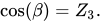
And, since

for we have

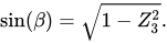
As is the double projection of a unitary vector,



There is a similar construction for , projecting it first over the axis (the resulting -axis after first two rotations) and then projecting the projection to the initial -axis. As the angle between -axis and -axis is and that between and -axis is and , this leads to:





and finally, using the inverse cosine function,



Tait–Bryan angles
[edit]
Assuming a frame with unit vectors (X, Y, Z) given by their coordinates as in this new diagram (notice that the angle theta is negative), it can be seen that:
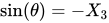
As before,

for we have

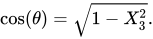
in a way analogous to the former one:


Looking for similar expressions to the former ones:



Last remarks
[edit]Note that the inverse sine and cosine functions yield two possible values for the argument. In this geometrical description, only one of the solutions is valid. When Euler angles are defined as a sequence of rotations, all the solutions can be valid, but there will be only one inside the angle ranges. This is because the sequence of rotations to reach the target frame is not unique if the ranges are not previously defined.[2]
For computational purposes, it may be useful to represent the angles using atan2(y, x). For example, in the case of proper Euler angles:


Conversion to other orientation representations
[edit]Euler angles are one way to represent orientations. There are others, and it is possible to change to and from other conventions. Three parameters are always required to describe orientations in a 3-dimensional Euclidean space. They can be given in several ways, Euler angles being one of them; see charts on SO(3) for others.
The most common orientation representations are the rotation matrices, the axis-angle and the quaternions, also known as Euler–Rodrigues parameters, which provide another mechanism for representing 3D rotations. This is equivalent to the special unitary group description.
Expressing rotations in 3D as unit quaternions instead of matrices has some advantages:
- Concatenating rotations is computationally faster and numerically more stable.
- Extracting the angle and axis of rotation is simpler.
- Interpolation is more straightforward. See for example slerp.
- Quaternions do not suffer from gimbal lock as Euler angles do.
Regardless, the rotation matrix calculation is the first step for obtaining the other two representations.
Rotation matrix
[edit]Any orientation can be achieved by composing three elemental rotations, starting from a known standard orientation. Equivalently, any rotation matrix R can be decomposed as a product of three elemental rotation matrices. For instance: is a rotation matrix that may be used to represent a composition of extrinsic rotations about axes z, y, x, (in that order), or a composition of intrinsic rotations about axes x-y′-z″ (in that order). However, both the definition of the elemental rotation matrices X, Y, Z, and their multiplication order depend on the choices taken by the user about the definition of both rotation matrices and Euler angles (see, for instance, Ambiguities in the definition of rotation matrices). Unfortunately, different sets of conventions are adopted by users in different contexts. The following table was built according to this set of conventions:

- Each matrix is meant to operate by pre-multiplying column vectors (see Ambiguities in the definition of rotation matrices)
- Each matrix is meant to represent an active rotation (the composing and composed matrices are supposed to act on the coordinates of vectors defined in the initial fixed reference frame and give as a result the coordinates of a rotated vector defined in the same reference frame).
- Each matrix is meant to represent, primarily, a composition of intrinsic rotations (around the axes of the rotating reference frame) and, secondarily, the composition of three extrinsic rotations (which corresponds to the constructive evaluation of the R matrix by the multiplication of three truly elemental matrices, in reverse order).
- Right handed reference frames are adopted, and the right hand rule is used to determine the sign of the angles α, β, γ.

For the sake of simplicity, the following table of matrix products uses the following nomenclature:
- X, Y, Z are the matrices representing the elemental rotations about the axes x, y, z of the fixed frame (e.g., Xα represents a rotation about x by an angle α).
- s and c represent sine and cosine (e.g., sα represents the sine of α).
| Proper Euler angles | Tait–Bryan angles |
|---|---|












These tabular results are available in numerous textbooks.[3] For each column the last row constitutes the most commonly used convention.
To change the formulas for passive rotations (or find reverse active rotation), transpose the matrices (then each matrix transforms the initial coordinates of a vector remaining fixed to the coordinates of the same vector measured in the rotated reference system; same rotation axis, same angles, but now the coordinate system rotates, rather than the vector). (Crystallographic Texture will typically use passive rotations.)
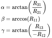
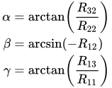
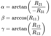
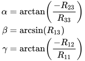
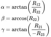
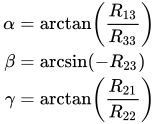
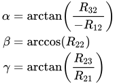
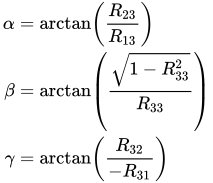
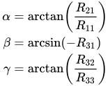
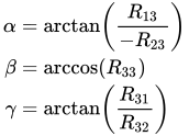
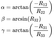
The following table contains formulas for angles α, β and γ from elements of a rotation matrix .[4]

| Proper Euler angles | Tait–Bryan angles | ||
|---|---|---|---|













Properties
[edit]The Euler angles form a chart on all of SO(3), the special orthogonal group of rotations in 3D space. The chart is smooth except for a polar coordinate style singularity along β = 0. See charts on SO(3) for a more complete treatment.
The space of rotations is called in general "The Hypersphere of rotations", though this is a misnomer: the group Spin(3) is isometric to the hypersphere S3, but the rotation space SO(3) is instead isometric to the real projective space RP3 which is a 2-fold quotient space of the hypersphere. This 2-to-1 ambiguity is the mathematical origin of spin in physics.
A similar three angle decomposition applies to SU(2), the special unitary group of rotations in complex 2D space, with the difference that β ranges from 0 to 2π. These are also called Euler angles.
The Haar measure for SO(3) in Euler angles is given by the Hopf angle parametrisation of SO(3), ,[5] where parametrise , the space of rotation axes.



For example, to generate uniformly randomized orientations, let α and γ be uniform from 0 to 2π, let z be uniform from −1 to 1, and let β = arccos(z).
Geometric algebra
[edit]Other properties of Euler angles and rotations in general can be found from the geometric algebra, a higher level abstraction, in which the quaternions are an even subalgebra. The principal tool in geometric algebra is the rotor where angle of rotation, is the rotation axis (unitary vector) and is the pseudoscalar (trivector in )
![{\displaystyle \mathbf {R} =[\cos(\theta /2)-Iu\sin(\theta /2)]}](https://wikimedia.org/api/rest_v1/media/math/render/svg/ccaf9643d65a54a5bd1b4d962d07f605c9c67648)


Higher dimensions
[edit]It is possible to define parameters analogous to the Euler angles in dimensions higher than three.[6] [7][unreliable source?] In four dimensions and above, the concept of "rotation about an axis" loses meaning and instead becomes "rotation in a plane." The number of Euler angles needed to represent the group SO(n) is n(n − 1)/2, equal to the number of planes containing two distinct coordinate axes in n-dimensional Euclidean space. (In other words, choose from n dimensions for the first axis, choose from the remaining n - 1 dimensions for the second axis, and then divide by two because it doesn't matter which of that pair was selected "first".)
In SO(4) a rotation matrix is defined by two unit quaternions, and therefore has six degrees of freedom, three from each quaternion.
Applications
[edit]Vehicles and moving frames
[edit]Their main advantage over other orientation descriptions is that they are directly measurable from a gimbal mounted in a vehicle. As gyroscopes keep their rotation axis constant, angles measured in a gyro frame are equivalent to angles measured in the lab frame. Therefore, gyros are used to know the actual orientation of moving spacecraft, and Euler angles are directly measurable. Intrinsic rotation angle cannot be read from a single gimbal, so there has to be more than one gimbal in a spacecraft. Normally there are at least three for redundancy. There is also a relation to the well-known gimbal lock problem of mechanical engineering.[8]
When studying rigid bodies in general, one calls the xyz system space coordinates, and the XYZ system body coordinates. The space coordinates are treated as unmoving, while the body coordinates are considered embedded in the moving body. Calculations involving acceleration, angular acceleration, angular velocity, angular momentum, and kinetic energy are often easiest in body coordinates, because then the moment of inertia tensor does not change in time. If one also diagonalizes the rigid body's moment of inertia tensor (with nine components, six of which are independent), then one has a set of coordinates (called the principal axes) in which the moment of inertia tensor has only three components.
The angular velocity of a rigid body takes a simple form using Euler angles in the moving frame. Also the Euler's rigid body equations are simpler because the inertia tensor is constant in that frame.
Crystallographic texture
[edit]
In materials science, crystallographic texture (or preferred orientation) can be described using Euler angles. In texture analysis, the Euler angles provide a mathematical depiction of the orientation of individual crystallites within a polycrystalline material, allowing for the quantitative description of the macroscopic material.[10] The most common definition of the angles is due to Bunge and corresponds to the ZXZ convention. It is important to note, however, that the application generally involves axis transformations of tensor quantities, i.e. passive rotations. Thus the matrix that corresponds to the Bunge Euler angles is the transpose of that shown in the table above.[11]
Others
[edit]
Euler angles, normally in the Tait–Bryan convention, are also used in robotics for speaking about the degrees of freedom of a wrist. They are also used in electronic stability control in a similar way, and also for pointing a camera in 3D modeling.
Gun fire control systems require corrections to gun-order angles (bearing and elevation) to compensate for deck tilt (pitch and roll). In traditional systems, a stabilizing gyroscope with a vertical spin axis corrects for deck tilt, and stabilizes the optical sights and radar antenna. However, gun barrels point in a direction different from the line of sight to the target, to anticipate target movement and fall of the projectile due to gravity, among other factors. Gun mounts roll and pitch with the deck plane, but also require stabilization. Gun orders include angles computed from the vertical gyro data, and those computations involve Euler angles.
Euler angles are also used extensively in the quantum mechanics of angular momentum. In quantum mechanics, explicit descriptions of the representations of SO(3) are very important for calculations, and almost all the work has been done using Euler angles. In the early history of quantum mechanics, when physicists and chemists had a sharply negative reaction towards abstract group theoretic methods (called the Gruppenpest), reliance on Euler angles was also essential for basic theoretical work.
Many mobile computing devices contain accelerometers which can determine these devices' Euler angles with respect to the earth's gravitational attraction. These are used in applications such as games, bubble level simulations, and kaleidoscopes.[citation needed]
See also
[edit]References
[edit]- ^ a b Novi Commentarii academiae scientiarum Petropolitanae 20, 1776, pp. 189–207 (E478) PDF
- ^ Gregory G. Slabaugh, Computing Euler angles from a rotation matrix
- ^ E.g. Appendix I (p. 483) of: Roithmayr, Carlos M.; Hodges, Dewey H. (2016). Dynamics: Theory and Application of Kane's Method (1st ed.). Cambridge University Press. ISBN 978-1107005693.
- ^ Henderson, D. M. (1977-06-09). Euler angles, quaternions, and transformation matrices for space shuttle analysis (Technical report). NASA. pp. 12–24.
- ^ Yershova, A.; Jain, S.; Lavalle, S. M.; Mitchell, J. C. (2010). "Generating Uniform Incremental Grids on SO(3) Using the Hopf Fibration". The International Journal of Robotics Research. 29 (7). Section 8 – Derivation of Hopf parametrisation. doi:10.1177/0278364909352700. PMC 2896220. PMID 20607113.
- ^ Hoffman, D. K. (1972), "Generalization of Euler Angles to N-Dimensional Orthogonal Matrices", Journal of Mathematical Physics, 13 (4), [J. Math. Phys. 13, 528–533]: 528–533, Bibcode:1972JMP....13..528H, doi:10.1063/1.1666011
- ^ (in Italian) A generalization of Euler Angles to n-dimensional real spaces
- ^ The relation between the Euler angles and the Cardan suspension is explained in chap. 11.7 of the following textbook: U. Krey, A. Owen, Basic Theoretical Physics – A Concise Overview, New York, London, Berlin, Heidelberg, Springer (2007) .
- ^ Liss KD, Bartels A, Schreyer A, Clemens H (2003). "High energy X-rays: A tool for advanced bulk investigations in materials science and physics". Textures Microstruct. 35 (3/4): 219–52. doi:10.1080/07303300310001634952.
- ^ Kocks, U.F.; Tomé, C.N.; Wenk, H.-R. (2000), Texture and Anisotropy: Preferred Orientations in Polycrystals and their effect on Materials Properties, Cambridge, ISBN 978-0-521-79420-6
- ^ Bunge, H. (1993), Texture Analysis in Materials Science: Mathematical Methods, Cuvillier Verlag, ASIN B0014XV9HU
Bibliography
[edit]- Biedenharn, L. C.; Louck, J. D. (1981), Angular Momentum in Quantum Physics, Reading, MA: Addison–Wesley, ISBN 978-0-201-13507-7
- Goldstein, Herbert (1980), Classical Mechanics (2nd ed.), Reading, MA: Addison–Wesley, ISBN 978-0-201-02918-5
- Gray, Andrew (1918), A Treatise on Gyrostatics and Rotational Motion, London: Macmillan (published 2007), ISBN 978-1-4212-5592-7
{{citation}}: ISBN / Date incompatibility (help) - Rose, M. E. (1957), Elementary Theory of Angular Momentum, New York, NY: John Wiley & Sons (published 1995), ISBN 978-0-486-68480-2
{{citation}}: ISBN / Date incompatibility (help) - Symon, Keith (1971), Mechanics, Reading, MA: Addison-Wesley, ISBN 978-0-201-07392-8
- Landau, L.D.; Lifshitz, E. M. (1996), Mechanics (3rd ed.), Oxford: Butterworth-Heinemann, ISBN 978-0-7506-2896-9
External links
[edit]
- "Euler angles", Encyclopedia of Mathematics, EMS Press, 2001 [1994]
- Weisstein, Eric W. "Euler Angles". MathWorld.
- David Eberly. Euler Angle Formulas, Geometric Tools
- An interactive tutorial on Euler angles available at https://www.mecademic.com/en/how-is-orientation-in-space-represented-with-euler-angles
- EulerAngles – an iOS app for visualizing in 3D the three rotations associated with Euler angles
- Orientation Library – "orilib", a collection of routines for rotation / orientation manipulation, including special tools for crystal orientations
- Online tool to convert rotation matrices available at rotation converter (numerical conversion)
- Online tool to convert symbolic rotation matrices (dead, but still available from the Wayback Machine) symbolic rotation converter
- Rotation, Reflection, and Frame Change: Orthogonal tensors in computational engineering mechanics, IOP Publishing
- Euler Angles, Quaternions, and Transformation Matrices for Space Shuttle Analysis, NASA

Euler angles
View on GrokipediaFundamentals
Definition and historical context
Euler angles constitute a three-parameter representation of the orientation of a rigid body in three-dimensional Euclidean space relative to a fixed reference frame. These angles, conventionally denoted as , , and , describe the body's attitude through a composition of three successive rotations about specified coordinate axes, enabling the transformation from the reference frame to the body frame. This parameterization draws on the geometric insight that any orientation in the special orthogonal group SO(3)—the Lie group of all proper rotations in 3D space—can be achieved via such sequential rotations around orthogonal axes, as established by Euler's foundational work on rigid body displacements.[5] A canonical example of this approach in proper Euler angles employs the z-x-z sequence: the first rotation by about the initial z-axis, followed by a rotation by about the intermediate x-axis, and concluding with a rotation by about the final z-axis. This method provides an intuitive, human-interpretable way to quantify and manipulate 3D orientations, particularly in fields requiring precise attitude control, though it is distinct from Tait-Bryan angles, which instead sequence rotations about three mutually perpendicular axes.[5] Leonhard Euler first introduced the concept of these three angles in his investigations into rigid body motion during the 1770s, culminating in the 1776 publication "Formulae generales pro translatione quacunque corporum rigidorum" in the Novi Commentarii Academiae Scientiarum Petropolitanae. In this seminal paper, Euler demonstrated that arbitrary finite displacements of a rigid body, preserving a fixed point, equate to a single rotation about an axis through that point, and he parameterized the general rotation using direction cosines and angles, laying the groundwork for the successive rotation framework. Earlier related ideas appeared in his paper "De motu corporum circa punctum fixum mobilium" (written after 1751, published posthumously in 1862) and the 1760 paper "Du mouvement d’un corps solide quelconque lorsqu’il tourne autour d’un axe mobile," where he explored angular velocity components via three angles for symmetric bodies.[6][7] The development of Euler angles continued to evolve in the 19th century, with significant advancements by French mathematician Benjamin Olinde Rodrigues, who in 1840 published explicit formulas for composing successive finite rotations and introduced parameters (now known as Euler-Rodrigues parameters) that complemented the angular description. Concurrently, Irish mathematician William Rowan Hamilton advanced rotation theory through his 1843-1844 invention of quaternions, a four-dimensional algebra that offered an alternative, non-singular parameterization of SO(3) and influenced subsequent refinements to Euler's angular methods. These contributions solidified Euler angles as a cornerstone of 3D rotation kinematics, bridging classical mechanics with modern group-theoretic interpretations.[8][9]Relation to rotations in 3D space
Euler's rotation theorem asserts that any orientation of a rigid body in three-dimensional Euclidean space can be achieved by a single rotation about some fixed axis passing through a point, such as the origin.[10] This theorem underpins the use of Euler angles, which provide an alternative representation by decomposing the same overall rotation into a sequence of three successive rotations about specific axes, either fixed in space or attached to the body.[11] Such decompositions are possible because the composition of three rotations suffices to span the full space of possible orientations, as rotations form a three-dimensional configuration space.[12] The equivalence between intrinsic and extrinsic rotation sequences arises from the properties of rotation matrix multiplication. In the extrinsic case, rotations are applied successively about fixed axes in the reference frame, resulting in a matrix product $ R = R_3 R_2 R_1 $, where each $ R_i $ is a rotation matrix about a fixed axis. For intrinsic rotations, the axes rotate with the body, leading to $ R = R_1 R_2 R_3 $, but with the axes updated after each step; this is mathematically equivalent to the extrinsic product with the order of rotations reversed, i.e., $ R_1 R_2 R_3 = R_3' R_2' R_1' $, where the primed matrices correspond to the reversed sequence.[13][14] This reversal ensures that both approaches yield the identical net orientation, as the non-commutativity of rotations is preserved through the adjusted order.[14] In the context of group theory, Euler angles serve as local coordinates on the special orthogonal group SO(3), which parameterizes all proper rotations in three dimensions as 3×3 orthogonal matrices with determinant 1.[12] Unlike a vector space, SO(3) is a non-commutative Lie group, meaning that the order of composing two rotations affects the result—rotating first around one axis and then another does not commute with the reverse order—necessitating careful sequencing in Euler angle representations.[15] To illustrate, consider orienting an object like a rigid frame: the first rotation might tilt it away from its initial alignment, the second adjusts the tilt direction, and the third spins it around the final axis, with the cumulative effect matching a direct axis-angle rotation but distributed across the three steps for intuitive decomposition.[11]Proper Euler Angles
Intrinsic rotation sequence
Proper Euler angles, also known as classic Euler angles, represent an orientation in three-dimensional space through a sequence of three successive rotations about axes that are fixed relative to the rotating body itself. This intrinsic approach contrasts with extrinsic rotations by updating the rotation axes after each step, ensuring that subsequent rotations occur in the body's local coordinate frame. Common sequences for proper Euler angles include z-x-z, z-y-z, and x-y-z, where the first and third axes coincide, allowing the parameterization to cover the full special orthogonal group SO(3) except for certain singular configurations.[13] Consider the z-x-z sequence as a representative example. The composition begins with an initial rotation by angle (precession) around the body's z-axis, denoted as . This is followed by a second rotation by angle (nutation) around the newly aligned x'-axis, represented by . Finally, a third rotation by angle (intrinsic rotation or spin) occurs around the updated z''-axis, given by . The overall rotation matrix is the product of these individual matrices in the order of application: , where the matrices are defined in the body-fixed frame and the multiplication reflects the intrinsic nature of the sequence.[16] The explicit form of the rotation matrices for the elemental rotations are standard in three dimensions:Extrinsic rotation sequence
In the extrinsic formulation of proper Euler angles, the orientation of a rigid body is described by a sequence of three successive rotations performed around fixed axes in the reference (space-fixed) coordinate frame, rather than axes attached to the body itself. This approach composes the rotations in a straightforward manner using the laboratory or world coordinate system, making it particularly suitable for scenarios where the reference frame remains stationary, such as in certain astronomical or simulation contexts. Unlike body-fixed rotations, each extrinsic rotation operates on the current orientation relative to the unchanging external axes, ensuring that the sequence directly accumulates transformations in the global frame.[13] A canonical example is the z-x-z extrinsic sequence, where the first rotation is by angle γ around the fixed z-axis, followed by a rotation by β around the fixed x-axis, and finally a rotation by α around the fixed z-axis. The resulting total rotation matrix R is obtained by multiplying the individual elementary rotation matrices in the order of application, from right to left:Conventions, signs, and ranges
In proper Euler angles, the sign convention for rotations adheres to the right-hand rule, where a positive rotation about an axis is defined such that the thumb of the right hand points along the positive direction of the axis and the fingers curl in the direction of the rotation.[19] This rule ensures consistency in defining the sense of rotation, with positive angles corresponding to counterclockwise motion when looking along the axis from the positive end, equivalent to a right-hand screw advancing into the positive direction.[20] Interpretations can be active, where rotations transform coordinates from a fixed frame to a body frame (intrinsic sequence), or passive, where they describe frame reorientations without moving the body (extrinsic sequence), though the resulting orientation matrix remains the same for equivalent sequences.[20] For the common z-x-z (or 3-1-3) sequence in proper Euler angles, typical ranges are chosen to cover all orientations uniquely while minimizing redundancy: the first angle α (or φ) spans 0 to 2π, the second angle β (or θ) spans 0 to π, and the third angle γ (or ψ) spans 0 to 2π.[21] These limits prevent overlap in most cases, as β exceeding π would duplicate orientations via reflection, and the 2π periodicity of α and γ accounts for full rotational symmetry.[22] In practice, software and fields like cryo-electron microscopy enforce these ranges to standardize computations.[22] Notations for proper Euler angles vary between historical and modern usages. Leonhard Euler originally employed Greek letters α, β, γ for the angles in his 1776 work on rigid body motion, with α as the initial rotation about the z-axis, β about the line of nodes (x'-axis in z-x-z), and γ about the final z''-axis.[23] Contemporary physics and engineering often use φ for precession (first angle), θ for nutation (second), and ψ for spin (third), particularly in the z-x-z convention prevalent in classical mechanics textbooks.[20] In aerospace applications, the 3-1-3 sequence (z-x-z) is occasionally used with φ, θ, ψ notation, though the more asymmetric 3-2-1 (z-y-x) Tait-Bryan sequence dominates for vehicle attitudes.[24] A key challenge with proper Euler angles is their non-uniqueness: the same orientation can correspond to multiple angle triples due to the periodicity and symmetries of rotations. For instance, in the z-x-z convention, (α, β, γ) represents the same orientation as (α + 2π, β, γ) or (α, 2π - β, -γ), and at β = 0 or β = π (gimbal lock points), infinitely many combinations arise since the intermediate axis aligns with the others.[22] Additionally, (α + π, π - β, γ + π) yields an equivalent rotation, reflecting the SO(3) group's properties.[25] These ambiguities are resolved through the standard range restrictions and field-specific conventions, ensuring a principal value set for each orientation.[19]Precession, nutation, and spin
In the z-x-z convention of proper Euler angles, the angles carry specific physical interpretations related to the components of a rigid body's rotation. The first angle, α, represents the precession, which is the rotation of the body's symmetry axis around the fixed space z-axis.[26] The second angle, β, denotes the nutation, corresponding to the tilt or nodding motion of the symmetry axis away from the fixed z-axis.[26] Finally, the third angle, γ, describes the intrinsic spin, which is the rotation of the body about its own symmetry axis.[26] These interpretations are particularly apt for symmetric rigid bodies, such as tops or spacecraft, where the z-axis aligns with the principal axis of inertia.[5] The instantaneous angular velocity vector ω of the body can be decomposed as the vector sum of contributions from each angle's time derivative, expressed in terms of the evolving reference frames:Tait-Bryan Angles
Definitions and sequences
Tait-Bryan angles represent the orientation of a rigid body in three-dimensional space through a sequence of three successive rotations about distinct axes, typically chosen from the orthogonal triad {x, y, z}.[5] These angles, also referred to as Cardan angles, form an asymmetric set in contrast to the symmetric proper Euler angles, which repeat the first and third rotation axes.[13] There are six possible Tait-Bryan sequences, corresponding to the six possible permutations of the three axes: 1-2-3 (XYZ), 1-3-2 (XZY), 2-1-3 (YXZ), 2-3-1 (YZX), 3-1-2 (ZXY), and 3-2-1 (ZYX).[5] A widely used example is the ZYX sequence, which applies a yaw rotation about the z-axis, followed by a pitch rotation about the intermediate y-axis, and a roll rotation about the final x-axis.[29] In the intrinsic formulation of the ZYX sequence, where each rotation is performed about the body-fixed axes updated after the previous rotation, the composite rotation matrix is composed asCommon conventions
In aviation and aerospace engineering, the most common Tait-Bryan convention employs the ZYX intrinsic rotation sequence, where the angles are yaw (ψ) about the z-axis, pitch (θ) about the y-axis, and roll (φ) about the x-axis, applied sequentially in the body-fixed frame.[https://stengel.mycpanel.princeton.edu/MAE331Lecture10.pdf] This 3-2-1 sequence begins with a yaw rotation about the initial vertical axis, followed by a pitch rotation about the intermediate lateral axis, and concludes with a roll rotation about the final longitudinal axis.[https://stengel.mycpanel.princeton.edu/MAE331Lecture10.pdf] The corresponding direction cosine matrix transforming from the inertial frame to the body frame is given by the productAlternative names and equivalences
Tait-Bryan angles are historically known as Cardan angles, named after the Italian polymath Gerolamo Cardano (1501–1576), who described the use of gimbals to maintain orientation in his 1550 work De subtilitate rerum. They are also referred to as Bryan angles, honoring the contributions of British mathematician George Hartley Bryan (1864–1928) to the kinematics of flight and rotation theory in the late 19th century. In modern engineering and robotics, these angles are commonly called roll-pitch-yaw (RPY) angles, where roll denotes rotation about the forward axis, pitch about the lateral axis, and yaw about the vertical axis, providing an intuitive parameterization for asymmetric body orientations. Tait-Bryan angles form a subclass of the broader family of Euler angle parameterizations, distinguished by their use of three distinct rotation axes (e.g., z-y-x) rather than the repeated axes characteristic of proper Euler angles (e.g., z-x-z). This asymmetry makes Tait-Bryan angles equivalent to proper Euler angles in the limit where the intermediate angle approaches specific values that align the effective axes, though both share the same underlying SO(3) manifold structure. Unlike proper Euler angles, which preserve rotational symmetry around a principal axis, Tait-Bryan sequences avoid inherent axis repetition, facilitating distinct mathematical treatments in non-symmetric contexts. Tait-Bryan angles are favored for applications requiring intuitive descriptions of vehicle or aircraft attitudes, such as in aerospace dynamics where yaw, pitch, and roll directly map to heading, elevation, and banking maneuvers. In contrast, proper Euler angles are typically employed in problems involving symmetric rigid bodies, like the torque-free motion of a spinning top, where the repeated axis aligns with the body's symmetry axis to simplify Lagrangian formulations. The following table summarizes common Tait-Bryan sequences, their conventional names, and typical domains of use:| Sequence (Intrinsic) | Angles | Common Name | Typical Use Case |
|---|---|---|---|
| z-y'-x'' | Yaw (ψ), Pitch (θ), Roll (φ) | Yaw-Pitch-Roll | Aerospace, mobile robotics |
| x-y'-z'' | Roll (φ), Pitch (θ), Yaw (ψ) | Roll-Pitch-Yaw | Computer graphics, some manipulators |
| z-y'-x'' | Yaw (ψ), Pitch (θ), Roll (φ) | Yaw-Pitch-Roll | Nautical navigation |