

Community hub
Recent from talks
Contribute something
Nothing was collected or created yet.
Gas engine
View on WikipediaThis article needs additional citations for verification. (September 2019) |


A gas engine is an internal combustion engine that runs on a fuel gas (a gaseous fuel), such as coal gas, producer gas, biogas, landfill gas, natural gas or hydrogen. In the United Kingdom and British English-speaking countries, the term is unambiguous. In the United States, due to the widespread use of "gas" as an abbreviation for gasoline (petrol), such an engine is sometimes called by a clarifying term, such as gaseous-fueled engine or natural gas engine.
Generally in modern usage, the term gas engine refers to a heavy-duty industrial engine capable of running continuously at full load for periods approaching a high fraction of 8,760 hours per year, unlike a gasoline automobile engine, which is lightweight, high-revving and typically runs for no more than 4,000 hours in its entire life. Typical power ranges from 10 kW (13 hp) to 4 MW (5,364 hp).[1]
History
[edit]


Lenoir
[edit]There were many experiments with gas engines in the 19th century, but the first practical gas-fuelled internal combustion engine was built by the Belgian engineer Étienne Lenoir in 1860.[2] However, the Lenoir engine suffered from a low power output and high fuel consumption.
Otto and Langen
[edit]Lenoir's work was further researched and improved by a German engineer Nicolaus August Otto, who was later to invent the first four-stroke engine to efficiently burn fuel directly in a piston chamber. In August 1864 Otto met Eugen Langen who, being technically trained, glimpsed the potential of Otto's development, and one month after the meeting, founded the first engine factory in the world, NA Otto & Cie, in Cologne. In 1867 Otto patented his improved design and it was awarded the Grand Prize at the 1867 Paris World Exhibition. This atmospheric engine worked by drawing a mixture of gas and air into a vertical cylinder. When the piston has risen about eight inches, the gas and air mixture is ignited by a small pilot flame burning outside, which forces the piston (which is connected to a toothed rack) upwards, creating a partial vacuum beneath it. No work is done on the upward stroke. The work is done when the piston and toothed rack descend under the effects of atmospheric pressure and their own weight, turning the main shaft and flywheels as they fall. Its advantage over the existing steam engine was its ability to be started and stopped on demand, making it ideal for intermittent work such as barge loading or unloading.[3]
Four-stroke engine
[edit]The atmospheric gas engine was in turn replaced by Otto's four-stroke engine. The changeover to four-stroke engines was remarkably rapid, with the last atmospheric engines being made in 1877. Liquid-fuelled engines soon followed using diesel (around 1898) or gasoline (around 1900).
Crossley
[edit]The best-known builder of gas engines in the United Kingdom was Crossley of Manchester, who in 1869 acquired the United Kingdom and world (except German) rights to the patents of Otto and Langen for the new gas-fuelled atmospheric engine. In 1876 they acquired the rights to the more efficient Otto four-stroke cycle engine. An engine is on display at Science and Industry Museum Manchester[4]
Tangye
[edit]There were several other firms based in the Manchester area as well. Tangye Ltd., of Smethwick, near Birmingham, sold its first gas engine, a 1 nominal horsepower two-cycle type, in 1881, and in 1890 the firm commenced manufacture of the four-cycle gas engine.[5]
Preservation
[edit]The Anson Engine Museum in Poynton, near Stockport, England, has a collection of engines that includes several working gas engines, including the largest running Crossley atmospheric engine ever made. A 3/4 AE & H Robinson engine is on display at Science and Industry Museum Manchester[6]
Current manufacturers
[edit]Manufacturers of gas engines include Hyundai Heavy Industries, Rolls-Royce with MTU, Bergen-Engines AS, Kawasaki Heavy Industries, Liebherr, MTU Friedrichshafen, INNIO Jenbacher, Caterpillar Inc., Perkins Engines, MWM, Cummins, Wärtsilä, INNIO Waukesha, Guascor Energy , Deutz, Everllence (formerly known as MAN Energy Solutions), Scania AB, Fairbanks-Morse, Doosan, Eaton (successor to another former large market share holder, Cooper Industries), and Yanmar. Output ranges from about 10 kW (13 hp) micro combined heat and power (CHP) to 18 MW (24,000 hp).[7] Generally speaking, the modern high-speed gas engine is very competitive with gas turbines up to about 50 MW (67,000 hp) depending on circumstances, and the best ones are much more fuel efficient than the gas turbines. Rolls-Royce with the Bergen Engines, Caterpillar and many other manufacturers base their products on a diesel engine block and crankshaft. INNIO Jenbacher and Waukesha are the only two companies whose engines are designed and dedicated to gas alone.
Typical applications
[edit]Stationary
[edit]Typical applications are base load or high-hour generation schemes, including combined heat and power (for typical performance figures see[8]), landfill gas, mines gas, well-head gas and biogas, where the waste heat from the engine may be used to warm the digesters. For typical biogas engine installation parameters see.[9] For parameters of a large gas engine CHP system, as fitted in a factory, see.[10] Gas engines are rarely used for standby applications, which remain largely the province of diesel engines. One exception to this is the small (<150 kW) emergency generator often installed by farms, museums, small businesses, and residences. Connected to either natural gas from the public utility or propane from on-site storage tanks, these generators can be arranged for automatic starting upon power failure.
Transport
[edit]Liquefied natural gas (LNG) engines are expanding into the marine market, as the lean-burn gas engine can meet the new emission requirements without any extra fuel treatment or exhaust cleaning systems. Use of engines running on compressed natural gas (CNG) is also growing in the bus sector. Users in the United Kingdom include Reading Buses. Use of gas buses is supported by the Gas Bus Alliance[11] and manufacturers include Scania AB.[12]
Use of gaseous methane or propane
[edit]Since natural gas, chiefly methane, has long been an economical and readily available fuel, many industrial engines are either designed or modified to use gas, as distinguished from gasoline. Their operation produces less complex-hydrocarbon pollution, and the engines have fewer internal problems. One example is the liquefied petroleum gas, chiefly propane. engine used in vast numbers of forklift trucks. Common United States usage of "gas" to mean "gasoline" requires the explicit identification of a natural gas engine, There is also such a thing as "natural gasoline",[13] but this term, which refers to a subset of natural gas liquids, is very rarely observed outside the refining industry.
Technical details
[edit]Fuel-air mixing
[edit]A gas engine differs from a petrol engine in the way the fuel and air are mixed. A petrol engine uses a carburetor or fuel injection. but a gas engine often uses a simple venturi system to introduce gas into the air flow. Early gas engines used a three-valve system, with separate inlet valves for air and gas.
Exhaust valves
[edit]The weak point of a gas engine compared to a diesel engine is the exhaust valves, since the gas engine exhaust gases are much hotter for a given output, and this limits the power output. Thus, a diesel engine from a given manufacturer will usually have a higher maximum output than the same engine block size in the gas engine version. The diesel engine will generally have three different ratings — standby, prime, and continuous, a.k.a. 1-hour rating, 12-hour rating and continuous rating in the United Kingdom, whereas the gas engine will generally only have a continuous rating, which will be less than the diesel continuous rating.
Ignition
[edit]Various ignition systems have been used, including hot-tube ignitors and spark ignition. Some modern gas engines are essentially dual-fuel engines. The main source of energy is the gas-air mixture but it is ignited by the injection of a small volume of diesel fuel.
Energy balance
[edit]Thermal efficiency
[edit]Gas engines that run on natural gas typically have a thermal efficiency between 35-45% (LHV basis).,[14] As of year 2018, the best engines can achieve a thermal efficiency up to 50% (LHV basis).[15] These gas engines are usually medium-speed engines Bergen Engines Fuel energy arises at the output shaft, the remainder appears as waste heat.[10] Large engines are more efficient than small engines. Gas engines running on biogas typically have a slightly lower efficiency (~1-2%) and syngas reduces the efficiency further still. GE Jenbacher's J624 engine from 2013 was the world's first high efficiency methane-fueled 24-cylinder gas engine.[16]
When considering engine efficiency one should consider whether this is based on the lower heating value (LHV) or higher heating value (HHV) of the gas. Engine manufacturers will typically quote efficiencies based on the lower heating value of the gas, i.e. the efficiency after energy has been taken to evaporate the intrinsic moisture within the gas itself. Gas distribution networks will typically charge based upon the higher heating value of the gas. i.e., total energy content. A quoted engine efficiency based on LHV might be say 44% whereas the same engine might have an efficiency of 39.6% based on HHV on natural gas. It is also important to ensure that efficiency comparisons are on a like-for-like basis. For example, some manufactures have mechanically driven pumps whereas other use electrically driven pumps to drive engine cooling water, and the electrical usage can sometimes be ignored giving a falsely high apparent efficiency compared to the direct drive engines.
Combined heat and power
[edit]Engine reject heat can be used for building heating or heating a process. In an engine, roughly half the waste heat arises (from the engine jacket, oil cooler and after-cooler circuits) as hot water, which can be at up to 110 °C. The remainder arises as high-temperature heat which can generate pressurised hot water or steam by the use of an exhaust gas heat exchanger.
Engine cooling
[edit]Two most common engine types are an air-cooled engine or water cooled engine. Water cooled nowadays use antifreeze in the internal combustion engine
Some engines (air or water) have an added oil cooler.
Cooling is required to remove excessive heat, as overheating can cause engine failure, usually from wear, cracking or warping.
Gas consumption formula
[edit]The formula shows the gas flow requirement of a gas engine in norm conditions at full load.

where:
- is the gas flow in norm conditions
- is the engine power
- is the mechanical efficiency
- LHV is the Low Heating Value of the gas


Gallery of historic gas engines
[edit]- Historic Gas Engines
-
 1905 National company's ordinary gas engine of 36 hp
 -
 1903 Körting gas engine
 -
 Backus upright gas engine
 -
 Otto horizontal gas engine
 -
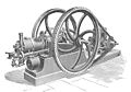
 Otto vertical gas engine
 -
 Westinghouse gas engine
 -
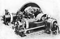
 Crossley gas engine and dynamo
 -
 Premier twin gas engine electric generating plant
 -
 125 hp gas engine and dynamo
 -
 Crossley Brothers Ltd., 1886 No. 1 Engine, 4.5 hp single cylinder, 4-stroke gas engine, 160 rpm.
 -
 1915 Crossley Gas Engine (type GE130 No75590), 150 hp.
 -
 National Gas Engine
 -
 Premier tandem scavenging high-power gas engine
 -
 Blast furnace gas engine with blowing cylinder
 -
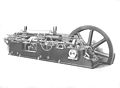
 Stockport gas engine and belt-driven dynamo
.jpg)
.jpg)
.jpg)
.jpg)
.jpg)
.jpg)
.jpg)
.jpg)
.jpg)


.jpg)
.jpg)
.jpg)
See also
[edit]References
[edit]- ^ "GE Jenbacher | Gas engines". Clarke-energy.com. Retrieved 2013-09-28.
- ^ "start your engines! — gas-engines". Library.thinkquest.org. Retrieved 2013-09-28.
- ^ "Crossley Atmospheric Gas Engine" (PDF). Museum of Science and Industry. Archived from the original (PDF) on 22 October 2013. Retrieved 23 September 2013.
- ^ Science museum group object no y1969 8
- ^ "The Basic Industries of Great Britain by Aberconway — Chapter XXI". Gracesguide.co.uk. Retrieved 2010-06-05.
- ^ Science museum group object no y1987.20
- ^ "Gas engines at Wärtsilä". Wartsila.com. Archived from the original on 2015-04-02. Retrieved 2013-09-28.
- ^ Andrews, Dave (2014-04-23). "Finning Caterpillar Gas Engine CHP Ratings | Claverton Group". Claverton-energy.com. Archived from the original on 2019-08-19. Retrieved 2014-08-09.
- ^ Andrews, Dave (2008-10-14). "38% HHV Caterpillar Bio-gas Engine Fitted to Sewage Works | Claverton Group". Claverton-energy.com. Archived from the original on 2019-08-19. Retrieved 2013-09-28.
- ^ a b Andrews, Dave (2010-06-24). "Complete 7 MWe Deutz (2 x 3.5MWe) gas engine CHP system for sale and re-installation in the country of your choice. Similar available on biogas / digester gas | Claverton Group". Claverton-energy.com. Archived from the original on 2013-09-30. Retrieved 2013-09-28.
- ^ "Global CNG Solutions Ltd — Gas Alliance Group". Globalcngsolutions.com. Archived from the original on 2017-06-27. Retrieved 2014-08-09.
- ^ "The UK's first Scania-ADL gas-powered buses delivered to Reading Buses". scania.co.uk. 2013-04-23. Retrieved 2014-08-09.
- ^ "Glossary — U.S. Energy Information Administration (EIA)". Retrieved 2018-12-22.
- ^ "CHP | Cogeneration | GE Jenbacher | Gas Engines". Clarke Energy. Archived from the original on 2012-04-30. Retrieved 2013-09-28.
- ^ "Rolls-Royce introducing new B36:45 gas engines to US market; up to 50% efficiency". Green Car Congress. Retrieved 2019-01-25.
- ^ "Products & Services". Ge-energy.com. Retrieved 2013-09-28.
| Types |
|  | ||||||||
|---|---|---|---|---|---|---|---|---|---|---|
| Infrastructure | ||||||||||
| Uses | ||||||||||
Gas engine
View on GrokipediaOverview and Classification
Definition and Principles
A gas engine is an internal combustion engine that operates by burning gaseous fuels, such as natural gas, propane, or hydrogen, to generate power through controlled explosions within cylinders.[11] These engines convert the chemical energy of the fuel into mechanical work by igniting a premixed fuel-air charge, distinguishing them from external combustion engines like steam engines, from which they evolved in the 19th century as a more compact and efficient alternative due to the internal location of combustion.[12] The basic operating principles of a gas engine involve reciprocating piston movement driven by the expansion of hot gases from combustion. The process typically follows a four-stroke cycle, consisting of intake (drawing in the gaseous fuel-air mixture), compression (reducing the mixture's volume to increase pressure and temperature), combustion (igniting the mixture to produce rapid gas expansion that forces the piston downward), and exhaust (expelling the combustion products).[1] Unlike engines using liquid fuels like gasoline or diesel, gas engines require no additional vaporization step since the fuel is already in gaseous form, simplifying fuel delivery systems and allowing for more uniform mixing with air.[13] Key differences from diesel or gasoline engines include the reliance on spark ignition—where an electric spark initiates combustion—rather than compression ignition, which occurs spontaneously in diesel engines due to high temperatures from extreme compression.[1] Gas engines typically operate at lower compression ratios, ranging from 8:1 to 12:1, to prevent knocking while accommodating the higher octane rating of gaseous fuels.[14]Types of Gas Engines
Gas engines are primarily classified by ignition method into spark-ignition (SI) and compression-ignition (dual-fuel) types. Spark-ignition gas engines ignite a premixed air-gas mixture using an electrical spark plug, operating on the Otto thermodynamic cycle where combustion occurs at constant volume. These engines are widely used for natural gas and other gaseous fuels in stationary and mobile applications due to their simplicity and compatibility with low-octane fuels. In contrast, dual-fuel gas engines utilize compression ignition, in which gaseous fuel is injected into pre-compressed air, and ignition is triggered by a pilot injection of diesel or another liquid fuel, mimicking the diesel cycle while deriving most energy from the gas. This configuration allows higher compression ratios and efficiency in large-scale operations but requires precise fuel management to avoid knocking.[15][16] Most gas engines operate on a four-stroke cycle, involving intake, compression, power, and exhaust strokes over two crankshaft revolutions, which provides better fuel efficiency and lower emissions compared to alternatives. The Otto cycle underpins the spark-ignition four-stroke design, emphasizing controlled combustion timing for optimal power output. Two-stroke gas engines, completing the cycle in one crankshaft revolution, are less common but used in large-scale applications such as marine propulsion and industrial compressors, where their higher power-to-weight ratio is advantageous despite increased lubricant consumption and emissions.[15][17][18] Gas engines are further categorized by size and power output to suit varying applications: small engines under 1 MW for portable, backup, and distributed power systems; medium engines from 1 to 10 MW for industrial cogeneration and combined heat and power (CHP) setups; and large engines exceeding 10 MW for utility-scale electricity generation and marine propulsion, often reaching over 60 MW in low-speed variants. Configuration options include inline arrangements for compact, smaller units with balanced vibration; V-type layouts for medium to large engines to shorten overall length while maintaining high cylinder counts; and opposed-piston designs in select high-efficiency models, where two pistons move toward each other in a single cylinder to eliminate valve mechanisms and improve scavenging.[18][19] Emerging gas engine types focus on sustainability and regulatory compliance, including hydrogen-ready variants that adapt spark-ignition or dual-fuel systems to combust hydrogen or hydrogen-natural gas blends, often with modified intake and ignition to mitigate backfiring and achieve near-zero carbon emissions. As of 2025, developments include Cummins' X15N natural gas engine for heavy-duty applications, supporting hydrogen blends and efficiencies exceeding 45%. Low-emission configurations incorporate advanced aftertreatment such as selective catalytic reduction (SCR) and oxidation catalysts to reduce NOx and unburned hydrocarbons, enabling compliance with global standards while maintaining operational flexibility across fuel types.[20][15][21]Historical Development
Early Inventions
The development of gas engines began in the mid-19th century with pioneering inventions that demonstrated the feasibility of internal combustion using gaseous fuels, marking a shift from external combustion engines like steam power. Étienne Lenoir, a Belgian inventor, constructed the first practical gas engine in 1860, a double-acting, two-stroke design that operated without compression on a mixture of coal gas and air.[22] This atmospheric engine ignited the mixture via an early electric spark system using a Ruhmkorff coil, producing power outputs typically around 0.5 to 2 horsepower in initial models, though larger versions reached up to 20 horsepower.[22] With an efficiency of approximately 4 percent, it consumed fuel at a high rate but proved durable and smooth-running, leading to commercial production of about 500 units by 1864, primarily for stationary applications in Paris.[23] Building on Lenoir's work, German engineers Nikolaus Otto and Eugen Langen introduced an improved prototype in 1867, featuring a free-piston design that allowed atmospheric intake without a fixed crankshaft connection, using a rack-and-pinion mechanism to engage power strokes selectively.[24] This vertical single-cylinder engine ran on illuminating gas, delivering about 0.5 horsepower at 110 revolutions per minute in standard configurations, with larger variants up to 3 horsepower, and achieved a thermal efficiency of around 16 percent—roughly double that of Lenoir's engine—by optimizing gas consumption through a weighted piston that only fired on downward strokes.[25] The design won a gold medal at the 1867 Paris Exposition for its economy, producing fewer vibrations than predecessors and enabling over 50 units to be built before production shifted to more advanced models.[24] Key technical advancements in early prototypes included the refinement of electric ignition systems during the 1880s, such as low-tension igniters and high-voltage vibrators, which improved reliability over initial hot-tube or open-flame methods by providing consistent sparks for non-compressed mixtures.[26] However, inventors faced significant hurdles with flame propagation in uncompressed gas-air mixtures, where low initial pressures resulted in slow burning speeds and incomplete combustion, often requiring enriched fuel blends to sustain ignition.[24] Valve timing also posed challenges, as slide valves in these atmospheric engines struggled to synchronize intake and exhaust precisely without compression to aid mixture flow, leading to inefficiencies and occasional backfiring that limited power consistency and operational speed.[22]Four-Stroke Cycle Introduction
The four-stroke cycle, patented by Nikolaus Otto in 1876, marked a pivotal advancement in internal combustion engine design by introducing a compressed charge mechanism that significantly improved efficiency over prior non-cyclic engines. This engine featured four distinct piston strokes: intake, where the air-fuel mixture is drawn into the cylinder; compression, where the mixture is compressed; power (or expansion), where combustion drives the piston; and exhaust, where spent gases are expelled. The initial design operated with a low compression ratio of approximately 3:1, enabling reliable operation on gaseous fuels like coal gas.[27][28] The thermodynamic foundation of Otto's cycle, known as the Otto cycle, approximates the engine's operation through an idealized sequence of processes for an ideal gas: isentropic compression (1-2), constant-volume heat addition (2-3) via combustion, isentropic expansion (3-4), and constant-volume heat rejection (4-1). During compression, the air-fuel mixture undergoes adiabatic compression, raising its temperature and pressure without heat transfer; heat addition then occurs at constant volume, simulating spark ignition. The thermal efficiency of this ideal cycle is derived from the first law of thermodynamics applied to the closed system. For heat input and heat rejection , efficiency is . Using isentropic relations and (where is the compression ratio and ), substitution yields . This formula highlights how higher compression ratios enhance efficiency, though limited by knocking in early gaseous fuel applications.[29][30] Subsequent refinements to Otto's engine in the late 1870s and 1880s included the adoption of slide valves for improved gas flow control and a water-cooling jacket around the cylinder to manage thermal loads, enabling more consistent performance. By the 1880s, these enhancements allowed power outputs to reach up to 3 horsepower at around 180 revolutions per minute, with thermal efficiencies approaching 14-15%. Building on earlier prototypes like the Lenoir engine, which lacked compression, Otto's cycle established a durable framework for stationary gas engines.[31][32] Otto's innovation had profound global repercussions, as his firm, Gasmotorenfabrik Deutz, licensed the four-stroke design to numerous European manufacturers, including Crossley Brothers in England, fostering widespread adoption and standardizing the cycle for gas engines across the continent. This dissemination propelled the transition from inefficient atmospheric engines to practical power sources for industrial applications.[33][28]Commercial Adoption and Preservation
The commercialization of gas engines accelerated in the late 1870s, driven by key manufacturers who scaled production for industrial applications. Crossley Brothers in Manchester, UK, began producing four-stroke gas engines in 1877 under license from Otto's firm Deutz, which had started production the previous year; they offered reliable, stationary units like the 4.5-horsepower horizontal model of 1886 used in foundries.[34] These engines, based on the Otto cycle, offered a cost-effective alternative to steam power, utilizing coal gas for consistent operation. Similarly, Tangye Brothers in Birmingham adapted gas engines during the 1880s for pumping applications, producing internal combustion models from 1881 onward based on James Robson's two-cycle design that powered water and hydraulic systems in industrial settings.[35] Early adoption was prominent in sectors requiring compact, on-site power, such as breweries for refrigeration and pumping and mines for ventilation and hoisting equipment, where gas engines reduced reliance on bulky steam boilers.[34] Market expansion was rapid, reflecting growing urban gas infrastructure. In the 1880s, production was limited to a few hundred units annually across Europe, primarily from firms like Crossley and Deutz. By 1900, however, thousands of gas engines were in operation worldwide, with Crossley alone selling over 20,000 by 1896 for diverse uses from textile mills to agriculture.[34] This growth coincided with the four-stroke cycle's refinement, enabling higher efficiency and broader scalability. Post-1900, the shift to natural gas accelerated as pipeline networks expanded—such as the 120-mile Indiana-to-Chicago line completed in 1891—making cleaner, more abundant fuel accessible and phasing out manufactured coal gas in many installations.[36] Preservation efforts today safeguard these early innovations, with museums maintaining operational examples to demonstrate 19th-century engineering. The Anson Engine Museum in the UK houses a collection of restored Crossley and Otto-Langen atmospheric gas engines from the 1870s-1880s, including a 3-horsepower model that runs on compressed air replicas of original gas mixtures. In Germany, the Deutsches Museum features a restored Otto-Langen free-piston engine and Lenoir-inspired prototypes, showcasing the transition from atmospheric to four-stroke designs. Restoration techniques emphasize non-invasive methods, such as electrolysis for derusting cast iron components to remove corrosion without metal loss, followed by precision polishing of brass fittings and application of historically accurate paints to prevent further degradation.[37] Modern exhibitions, like those at the Science and Industry Museum, highlight operational 19th-century engines in simulated factory environments, educating on their role in industrialization. The legacy of these early gas engines profoundly shaped automotive development, as the four-stroke Otto cycle became the foundation for gasoline internal combustion engines in vehicles from the 1890s onward. Over 50 preserved operational examples from the 19th century exist worldwide, concentrated in institutions like the Coolspring Power Museum in the US, which maintains around 250 historic engines, many gas-powered and runnable.[38] These artifacts not only illustrate the shift from stationary to mobile power but also underscore gas engines' contributions to energy efficiency standards still relevant today.Design and Components
Fuel-Air Mixing Systems
In gas engines, which primarily utilize gaseous fuels such as natural gas or biogas, fuel-air mixing systems are essential for creating a homogeneous or stratified charge that ensures efficient combustion while minimizing emissions and knock. These systems prepare the fuel-air mixture either before intake into the cylinder (premixing) or directly within the combustion chamber, adapting to the gaseous nature of the fuel that requires less atomization than liquid fuels but emphasizes uniform distribution and precise ratio control.[18] Premixing techniques dominate in smaller and medium-sized gas engines, where gaseous fuel is introduced at low pressure and blended with air in the intake manifold or via carburetor-like mixers. In carburetor-based systems, common since the late 19th century, the venturi effect draws gas into the airstream, promoting homogeneity by leveraging the pressure drop to mix the fuel evenly without needing fine atomization, as the gaseous fuel disperses readily. This approach suits low-pressure supplies and allows for straightforward operation in stationary applications.[18] Direct injection systems, particularly high-pressure variants, are employed in larger engines for enhanced performance, injecting gaseous fuel directly into the cylinder after the intake valve closes. This method, typically at pressures up to 300 bar with some advanced systems exceeding this, enables better control over mixture stratification, reducing the risk of pre-ignition and knock by limiting excessive premixing during compression. Advantages include improved load flexibility and higher substitution rates of gaseous fuel in dual-fuel setups, achieving up to 95% diesel replacement in heavy-duty applications while maintaining diesel-like efficiency.[18][39] Air-fuel ratios in gas engines vary by operating mode, with stoichiometric mixtures around 17.2:1 for methane-based natural gas ensuring complete combustion for three-way catalyst compatibility in rich-burn setups. Lean-burn configurations, targeting ratios of 18:1 or higher, enhance thermal efficiency by reducing peak temperatures and NOx formation, often aided by in-cylinder turbulence promoters such as swirl-inducing intake ports to maintain mixture homogeneity.[18][40][41] The evolution of these systems began in the 1870s with atmospheric premixing in early Otto-cycle engines, where gas and air were simply drawn into the cylinder via slide valves without pressurized delivery. By the early 20th century, mixer-carburetors refined this for commercial stationary engines, and modern developments incorporate electronic fuel injection controls for precise metering and adaptive ratios, enabling lean-burn and direct injection in high-output units like marine engines exceeding 60 MW.[18][34][42]Ignition and Combustion
In gas engines, ignition is initiated through spark ignition systems that generate a high-voltage electrical discharge to ignite the premixed fuel-air charge in the combustion chamber. These systems typically employ inductive high-voltage coils, which store energy in a primary winding and release it as a high-tension spark (up to 40,000 volts or more) across the spark plug electrodes via a secondary winding.[43] Traditional setups use a distributor to sequentially route the spark to each cylinder in the firing order, rotating at half crankshaft speed, while modern systems rely on electronic control units (ECUs) for distributorless operation, using crankshaft position sensors to precisely time the discharge.[43] Gaseous fuels, such as natural gas, often require higher breakdown voltages due to the lower electrical conductivity of lean premixed mixtures compared to liquid fuels.[43] Recent adaptations include ECU-optimized timing for hydrogen-natural gas blends to support sustainable fuel transitions as of 2025.[44] Ignition timing is dynamically advanced or retarded by the ECU based on engine speed (RPM) and load, typically measured via manifold absolute pressure or throttle position sensors, to optimize combustion efficiency and prevent detonation. At higher RPMs, advance increases to compensate for the shorter time available for flame development, while under high load, it may be retarded to avoid knock.[45] This ECU-controlled adjustment ensures the spark occurs 10–40 degrees before top dead center (BTDC), adapting in real-time to maintain maximum brake torque timing.[43] Once ignited, combustion in gas engines proceeds as a premixed turbulent flame front propagating through the cylinder, characterized by faster flame speeds in gaseous mixtures—typically 5–10 m/s under turbulent conditions—compared to the slower evaporation-limited propagation in liquid-fueled engines.[46] This rapid propagation enhances thermal efficiency but increases knock risk, where unburned end-gas auto-ignites ahead of the flame, causing pressure spikes. Knock is detected using in-cylinder pressure sensors or accelerometers that monitor vibration frequencies (5–20 kHz), triggering the ECU to retard timing by 5–15 degrees to slow flame advancement and reduce end-gas compression heating.[47] [48] Spark plug electrodes in gas engines feature fine-wire tips made of platinum or iridium alloys to withstand the high-temperature, lean-burn conditions that accelerate electrode erosion in gaseous combustion. Iridium, with its high melting point (over 2,400°C) and superior wear resistance, extends plug life to typically 3,000–5,000 hours in stationary applications, outperforming platinum by reducing gap growth from thermal and chemical degradation.[49][50] For large-bore cylinders (over 200 mm diameter), dual-spark configurations—using two plugs per cylinder—promote symmetric flame kernels, shortening burn duration by up to 20% and minimizing misfires in lean mixtures.[51] Safety features mitigate risks from incomplete combustion or backfire, including flame arrestors installed on the intake manifold to quench propagating flames and prevent ignition of external fuel-air mixtures. These devices use wire mesh or perforated plates to dissipate flame energy, complying with standards like NFPA 37 for stationary engines. Additionally, ECUs incorporate auto-shutoff mechanisms that disable ignition upon detecting misfires via ion-sensing or pressure feedback, averting unburned fuel accumulation and potential explosions.[52]Valves and Exhaust Mechanisms
In gas engines, poppet valves are the predominant type used to regulate the intake of the air-fuel mixture and the expulsion of exhaust gases, operating through a lifting motion driven by the camshaft.[53] These valves are typically arranged in an overhead configuration with camshafts positioned above the combustion chamber to enable precise control and reduce mechanical complexity in the valvetrain.[54] Exhaust valves, in particular, incorporate sodium-filled stems to enhance cooling, as the sodium liquefies at operating temperatures and transfers heat from the valve head to the stem via agitation during reciprocation, mitigating thermal stress in environments reaching up to 700°C.[55] Valve timing in four-stroke gas engines is synchronized with the crankshaft using chain-driven or gear systems to ensure proper opening and closing during the intake, compression, power, and exhaust strokes.[56] Chains provide flexibility for overhead camshaft layouts and are often preferred in larger engines for their durability under high loads, while gears offer direct drive with minimal maintenance in compact designs.[57] Modern gas engines increasingly employ variable valve timing (VVT) mechanisms, such as cam phasers controlled by oil pressure, to dynamically adjust intake and exhaust valve events based on engine speed and load, thereby optimizing volumetric efficiency and improving fuel economy by up to 5%.[58] Exhaust systems in gas engines typically integrate turbocharging to recover energy from hot exhaust gases, driving a turbine that compresses intake air for higher power output, a feature common in large stationary units to boost efficiency without increasing engine size.[59] In lean-burn configurations, which operate with excess air to minimize fuel use, catalytic converters are employed to reduce emissions of NOx and CO through oxidation and selective catalytic reduction processes, achieving up to 80% NOx conversion in stationary applications.[60] A key durability challenge in gas engines arises from valve seat recession, exacerbated by low-ash lubricants in gaseous fuel operation, which accelerates wear on exhaust valve seats due to increased friction and heat, potentially leading to loss of compression and engine failure.[61][62] This issue is mitigated by installing hardened valve seat inserts made from materials like stellite or nickel-based alloys, which provide superior resistance to recession and extend component life under lead-free conditions.[63]Fuels and Energy Management
Gaseous Fuel Usage
Gas engines primarily utilize gaseous fuels such as natural gas, liquefied petroleum gas (LPG), and biogas, each offering distinct properties suited to internal combustion processes. Natural gas, composed predominantly of methane (typically 90-95% CH₄), serves as the most common fuel, with a lower heating value of approximately 38 MJ/m³, enabling efficient combustion in stationary and mobile applications.[64][65] LPG, a mixture of propane (C₃H₈) and butane (C₄H₁₀), provides a higher energy density with a calorific value of about 93 MJ/m³ when vaporized, making it suitable for higher-power demands despite its liquid storage form.[66] Biogas, derived from organic waste decomposition, contains 50-70% methane along with CO₂ and trace gases, yielding a variable calorific value of 20-25 MJ/m³, which supports renewable energy integration but requires purification for optimal engine performance. Renewable natural gas (RNG), an upgraded form of biogas, can achieve near-zero or negative greenhouse gas emissions through carbon capture in production, enhancing sustainability in gas engine applications.[67] Adaptations in gas engines ensure compatibility with these fuels' physical states and combustion characteristics. For low-pressure natural gas, carburetion systems mix the fuel with air via venturi-based devices, delivering a homogeneous charge without high-pressure injection.[65] LPG, stored as a liquid, necessitates vaporizers to convert it to gas prior to mixing, often using engine coolant or electric heating to maintain consistent vapor pressure and prevent liquid ingress into the engine.[68] Hydrogen blending into natural gas, typically up to 20% by volume but with recent tests demonstrating up to 50% as of 2025, enhances decarbonization by reducing carbon content, but requires ignition timing adjustments to account for hydrogen's faster flame speed and wider flammability limits, preventing knock or incomplete combustion.[69][70][71] Storage and delivery systems are tailored to fuel type and application. In vehicles, compressed natural gas (CNG) is stored at 200-250 bar in high-strength cylinders to achieve sufficient energy density for range, while stationary engines often draw from pipeline natural gas at near-atmospheric pressure.[72] Interchangeability between gas sources relies on the Wobbe index, a measure combining calorific value and specific gravity, ensuring consistent energy delivery through fixed orifices without engine modifications.[73] Environmentally, gaseous fuels in gas engines produce negligible soot or particulate matter compared to liquid fuels like diesel, due to the absence of heavy hydrocarbons and cleaner premixed combustion.[74] However, they exhibit a higher potential for NOx formation under lean-burn conditions from elevated combustion temperatures.[74] CO₂ emissions from natural gas equivalents are approximately 20-25% lower than diesel on a well-to-wheel basis, attributed to methane's lower carbon-to-hydrogen ratio and reduced upstream processing impacts.[74]Thermal Efficiency and Heat Recovery
Modern spark-ignition (SI) gas engines achieve brake thermal efficiencies (BTE) typically ranging from 35% to 45% on a lower heating value (LHV) basis, with large lean-burn units exceeding 45% and approaching 50% in advanced designs.[15][75] Key factors influencing this efficiency include higher compression ratios, which can boost BTE by approximately 1.6% per unit increase when enabled by fuel properties, and lean-burn operation, which enhances thermodynamic performance while reducing NOx emissions, though low-NOx tuning may reduce efficiency by 1-1.5%.[76][15] In gas engines operating on the Otto cycle, energy losses limit practical efficiencies to below the theoretical maximum of around 60%, with typical breakdowns showing 25-30% of fuel energy lost as exhaust heat, 20-25% as cooling losses from jacket water and lubrication, and about 10% to mechanical friction and pumping.[15][77] Compared to alternatives like the Diesel cycle, the Otto cycle's constant-volume combustion imposes inherent limits due to knock constraints in SI engines, restricting compression ratios and thus expansion efficiency.[78] Heat recovery systems significantly enhance overall energy utilization in gas engines through combined heat and power (CHP) cogeneration, where waste heat from exhaust gases (typically 400-500°C) and jacket water (80-90°C) is captured for applications such as steam generation or space heating.[15][79] This approach achieves total CHP system efficiencies of 80-90% (higher heating value basis) by recovering 60-70% of the fuel's rejected heat, far surpassing standalone engine operation.[15][80] Optimization techniques such as intercooling and the Miller cycle further improve efficiency in turbocharged gas engines by addressing key losses. Intercooling cools the intake charge to enable higher boost pressures without excessive knock, supporting elevated compression ratios and reducing heat transfer losses.[81] The Miller cycle, employing early inlet valve closing to create an over-expansion ratio greater than the compression ratio, reduces pumping losses at part loads and can yield 4-10% improvements in fuel efficiency, particularly in downsized boosted configurations.[82][81]Cooling and Gas Consumption Calculations
Gas engines employ various cooling strategies to manage the significant heat generated during combustion, particularly from gaseous fuels that produce high flame temperatures. Liquid cooling systems predominate in medium- to large-scale applications, utilizing a mixture of glycol and water—typically 40% glycol concentration—to provide freeze protection down to approximately -30°C while facilitating efficient heat transfer.[83] In these systems, coolant enters the engine at around 80°C and exits at 95°C, circulating through jackets surrounding the cylinders and heads to absorb and dissipate heat via radiators or external exchangers.[84] This approach ensures uniform temperature distribution and prevents thermal stresses, with pumps maintaining flow rates that account for 2-5% of the engine's total output power.[85] Air cooling is more common in small gas engines, such as those under 20 kW used in portable generators or light-duty equipment, where fins on the cylinder and head surfaces promote direct heat dissipation via forced airflow from integral fans.[86] This method simplifies design and reduces weight but requires unobstructed airflow to avoid overheating, making it suitable for intermittent operation rather than continuous high-load duty. For combined heat and power (CHP) integration, heat exchangers capture cooling system output—such as jacket water at 85-95°C—for secondary uses like district heating, enhancing overall system efficiency without compromising engine thermal management.[87] Effective thermal management focuses on the cylinder head, where gas combustion can create localized hotspots exceeding 2000°C, risking detonation or material degradation if not addressed. Specialized coolant jackets around the prechamber and exhaust valve areas direct higher flow rates to these regions, often using computational fluid dynamics-optimized designs to equalize temperatures and prevent uneven expansion.[88] Auxiliary components like fans for air-cooled variants or pumps for liquid systems introduce minor parasitic losses, typically consuming 2-5% of gross output, which must be factored into net efficiency calculations.[89] Gas consumption in gas engines is calculated from the fundamental energy balance, where output power equals the product of fuel energy input and thermal efficiency. The volume of gas required, in cubic meters per hour (m³/h), is given by: Here, is the engine power in kilowatts (kW), is the thermal efficiency (as a decimal, e.g., 0.40 for 40%), and is the lower heating value of the gas in megajoules per cubic meter (MJ/m³), typically 35-40 MJ/m³ for natural gas. This formula derives from equating mechanical output to efficient fuel energy: power in kW converts to MJ/h via multiplication by 3.6 (since 1 kW = 3.6 MJ/h), rearranged to solve for volume flow after accounting for efficiency and heating value units. For example, a 500 kW engine at 38% efficiency consuming natural gas with HV = 37 MJ/m³ yields m³/h, establishing baseline operational needs. At part loads, gas consumption rises disproportionately relative to output, often by 20-50% on a specific basis (m³/kWh), due to the need for richer mixtures to ensure stable ignition and combustion. Lean-burn gas engines, optimized for full-load efficiency, require enrichment at loads below 50% to avoid misfire, increasing the air-fuel ratio toward stoichiometric and elevating unburned hydrocarbon emissions alongside fuel use.[91] This behavior underscores the importance of load-matching in applications like variable-demand power generation.Applications and Modern Uses
Stationary Power Generation
Reciprocating gas engines are widely utilized in stationary power generation for distributed systems, typically ranging from 1 to 50 MW per unit, enabling modular configurations that can scale to meet varying demands in power plants.[15] These engines offer superior flexibility compared to gas turbines, particularly in integrating renewable energy sources like wind and solar, due to their rapid start-up times—often under 5 minutes—and ability to handle frequent load cycling without significant efficiency losses.[92] This makes them ideal for distributed generation applications where grid stability is challenged by intermittent renewables.[93] In industrial settings, gas engines provide reliable backup power and support cogeneration (CHP) systems, capturing waste heat for processes such as steam generation in food processing facilities, thereby enhancing overall energy utilization.[94] For instance, in factories, these engines can deliver both electricity and thermal energy, with waste heat used for drying or heating applications, achieving system efficiencies up to 90% in CHP configurations.[80] Additionally, their inherent black-start capability allows independent grid restoration during outages, without external power support, which is critical for industrial continuity.[95] Multi-engine plants, often comprising 10-20 units, are employed for base-load operations in stationary setups, providing continuous power output while maintaining high reliability through redundancy.[96] Emissions compliance is achieved via selective catalytic reduction (SCR) systems, reducing NOx levels to below 500 mg/Nm³ at 5% oxygen, meeting stringent environmental regulations for natural gas-fired installations.[97] In Europe, gas engine-based peaking plants have proliferated since the early 2000s, with installations exceeding 450 MWe in the UK alone for flexible response to demand spikes and renewable variability.[98]Transportation and Mobile Uses
Gas engines have found significant application in the automotive sector, particularly in compressed natural gas (CNG) powered buses and trucks, where engines typically deliver power outputs in the range of 200-300 kW to meet urban and regional transport demands.[99] These vehicles benefit from the cleaner combustion of CNG, reducing emissions compared to diesel equivalents, though range limitations typically restrict operation to 300-500 km per fill due to the lower energy density of gaseous fuels.[100] To address these constraints in heavy-duty applications, such as long-haul trucking, liquefied natural gas (LNG) variants are employed, enabling ranges exceeding 1,000 km and supporting extended operations without frequent refueling.[101] In marine and rail transport, gas engines serve as auxiliary power units and dual-fuel systems to comply with stringent emission regulations. Natural gas auxiliary engines on ships significantly reduce sulfur oxide (SOx) emissions by nearly eliminating sulfur content in the fuel, making them suitable for operations in emission control areas.[102] For rail, dual-fuel locomotives combining natural gas and diesel are used in switching yards and urban settings, such as those operated by the Indiana Harbor Belt Railroad in Chicago, allowing seamless transitions between fuels to optimize efficiency and lower emissions during low-speed maneuvering.[103] Portable gas engines under 100 kW are widely utilized in oilfield operations for powering generators and compressors, providing reliable, on-site energy from natural gas sources like wellhead gas. These lightweight designs facilitate mobility in remote locations, supporting tasks such as drilling support and equipment operation without the logistical burdens of diesel fuel transport.[104] Despite these advantages, challenges persist in mobile applications, including the added weight from CNG storage cylinders, which can increase vehicle mass by 20-30% and impact payload capacity.[105] Additionally, the growth of refueling infrastructure since the 2010s—with U.S. CNG stations rising from 841 in 2010 to over 1,700 by the mid-2010s and global numbers exceeding 30,000 as of 2023—has been crucial in expanding adoption, though uneven distribution remains a barrier in some regions.[106][107] Gaseous fuel storage systems, often requiring high-pressure cylinders, further emphasize the need for optimized tank designs to mitigate these issues.[108]Current Manufacturers and Innovations
Leading manufacturers of stationary gas engines include Caterpillar Inc., MAN Energy Solutions, and INNIO Jenbacher, which collectively hold a substantial portion of the global market for power generation applications. Caterpillar's G3400 series engines are designed for petroleum and industrial uses, offering reliable performance in continuous operations with features like improved cooling and oil control for extended overhaul intervals. MAN Energy Solutions' TCG series, such as the TCG 2020 model, supports combined heat and power (CHP) systems, delivering electrical efficiencies up to 44% while utilizing natural gas or biogas. INNIO Jenbacher, formerly under GE ownership and now independently operated, provides engines ranging from 250 kW to 10 MW, tailored for distributed power generation and renewable fuel integration.[109][110][111] Recent innovations focus on enhancing efficiency and adaptability. Variable geometry turbochargers (VGTs) in gas engines adjust turbine geometry to optimize airflow across operating ranges, achieving efficiency improvements of 5-10% by reducing turbo lag and enhancing low-speed torque. Digital twins, virtual replicas of engines, enable predictive maintenance through real-time data simulation, minimizing downtime and optimizing performance in applications like power plants. Hydrogen conversion kits allow existing engines to transition to up to 100% hydrogen fuel, with manufacturers targeting full compatibility by 2030 to support decarbonization goals.[112][113][114] Environmental advancements emphasize emissions reduction. Exhaust gas recirculation (EGR) systems recirculate cooled exhaust to lower combustion temperatures, cutting NOx emissions while maintaining high thermal efficiency. Plasma ignition technologies generate non-thermal plasma for more complete combustion, enabling near-zero emissions and supporting high EGR rates up to 35% with stable operation. Integration with battery storage in hybrid systems allows gas engines to handle peak loads efficiently, combining rapid battery response with steady engine output for overall system decarbonization.[115][116][117] Market trends highlight growth in Asia, where biogas engine demand is expanding due to agricultural waste utilization and urbanization, projecting a CAGR over 10% through 2033. Post-2020, the sector has shifted toward decarbonization, driven by regulations like the EU Stage V standards, which mandate stringent emissions limits for non-road gas engines to promote cleaner stationary power.[118][119]References
- https://www.grc.[nasa](/page/NASA).gov/www/k-12/airplane/sfc.html