

Community hub
Recent from talks
Contribute something
Nothing was collected or created yet.
Injection moulding
View on WikipediaThis article needs additional citations for verification. (July 2025) |

Injection moulding (U.S. spelling: Injection molding) is a manufacturing process for producing parts by injecting molten material into a mould, or mold. Injection moulding can be performed with a host of materials mainly including metals (for which the process is called die-casting), glasses, elastomers, confections, and most commonly thermoplastic and thermosetting polymers. Material for the part is fed into a heated barrel, mixed (using a helical screw), and injected into a mould cavity, where it cools and hardens to the configuration of the cavity.[1]: 240 After a product is designed, usually by an industrial designer or an engineer, moulds are made by a mould-maker (or toolmaker) from metal, usually either steel or aluminium, and precision-machined to form the features of the desired part. Injection moulding is widely used for manufacturing a variety of parts, from the smallest components to entire body panels of cars. Advances in 3D printing technology, using photopolymers that do not melt during the injection moulding of some lower-temperature thermoplastics, can be used for some simple injection moulds.

Injection moulding uses a special-purpose machine that has three parts: the injection unit, the mould and the clamp. Parts to be injection-moulded must be very carefully designed to facilitate the moulding process; the material used for the part, the desired shape and features of the part, the material of the mould, and the properties of the moulding machine must all be taken into account. The versatility of injection moulding is facilitated by this breadth of design considerations and possibilities.
Applications
[edit]
Injection moulding is used to create many things such as wire spools, packaging, bottle caps, automotive parts and components, toys, pocket combs, some musical instruments (and parts of them), one-piece chairs and small tables, storage containers, mechanical parts (including gears), and most other plastic products available today. Injection moulding is the most common modern method of manufacturing plastic parts; it is ideal for producing high volumes of the same object.[2]
Process characteristics
[edit]
Injection moulding uses a ram or screw-type plunger to force molten plastic or rubber material into a mould cavity; this solidifies into a shape that has conformed to the contour of the mould. It is most commonly used to process both thermoplastic and thermosetting polymers, with the volume used of the former being considerably higher.[3]: 1–3 Thermoplastics are prevalent due to characteristics that make them highly suitable for injection moulding, such as ease of recycling, versatility for a wide variety of applications,[3]: 8–9 and ability to soften and flow on heating. Thermoplastics also have an element of safety over thermosets; if a thermosetting polymer is not ejected from the injection barrel in a timely manner, chemical crosslinking may occur causing the screw and check valves to seize and potentially damaging the injection moulding machine.[3]: 3
Injection moulding consists of the high pressure injection of the raw material into a mould, which shapes the polymer into the desired form.[3]: 14 Moulds can be of a single cavity or multiple cavities. In multiple cavity moulds, each cavity can be identical and form the same parts or can be unique and form multiple different geometries during a single cycle. Moulds are generally made from tool steels, but stainless steels and aluminium moulds are suitable for certain applications. Aluminium moulds are typically ill-suited for high volume production or parts with narrow dimensional tolerances, as they have inferior mechanical properties and are more prone to wear, damage, and deformation during the injection and clamping cycles; however, aluminium moulds are cost-effective in low-volume applications, as mould fabrication costs and time are considerably reduced.[1] Many steel moulds are designed to process well over a million parts during their lifetime and can cost hundreds of thousands of dollars to fabricate.[citation needed]
When thermoplastics are moulded, typically pelletised raw material is fed through a hopper into a heated barrel with a reciprocating screw. Upon entrance to the barrel, the temperature increases and the Van der Waals forces that resist relative flow of individual chains are weakened as a result of increased space between molecules at higher thermal energy states. This process reduces its viscosity, which enables the polymer to flow with the driving force of the injection unit. The screw delivers the raw material forward, mixes and homogenises the thermal and viscous distributions of the polymer, and reduces the required heating time by mechanically shearing the material and adding a significant amount of frictional heating to the polymer. The material feeds forward through a check valve and collects at the front of the screw into a volume known as a shot. A shot is the volume of material that is used to fill the mould cavity, compensate for shrinkage, and provide a cushion (approximately 10% of the total shot volume, which remains in the barrel and prevents the screw from bottoming out) to transfer pressure from the screw to the mould cavity. When enough material has gathered, the material is forced at high pressure and velocity into the part forming cavity. The exact amount of shrinkage is a function of the resin being used, and can be relatively predictable.[4] To prevent spikes in pressure, the process normally uses a transfer position corresponding to a 95–98% full cavity where the screw shifts from a constant velocity to a constant pressure control. Often injection times are well under 1 second. Once the screw reaches the transfer position the packing pressure is applied, which completes mould filling and compensates for thermal shrinkage, which is quite high for thermoplastics relative to many other materials. The packing pressure is applied until the gate (cavity entrance) solidifies. Due to its small size, the gate is normally the first place to solidify through its entire thickness.[3]: 16 Once the gate solidifies, no more material can enter the cavity; accordingly, the screw reciprocates and acquires material for the next cycle while the material within the mould cools so that it can be ejected and be dimensionally stable. This cooling duration is dramatically reduced by the use of cooling lines circulating water or oil from an external temperature controller. Once the required temperature has been achieved, the mould opens and an array of pins, sleeves, strippers, etc. are driven forward to demould the article. Then, the mould closes and the process is repeated.[citation needed]
For a two-shot mould, two separate materials are incorporated into one part. This type of injection moulding is used to add a soft touch to knobs, to give a product multiple colours, or to produce a part with multiple performance characteristics.[5]
For thermosets, typically two different chemical components are injected into the barrel. These components immediately begin irreversible chemical reactions that eventually crosslinks the material into a single connected network of molecules. As the chemical reaction occurs, the two fluid components permanently transform into a viscoelastic solid.[3]: 3 Solidification in the injection barrel and screw can be problematic and have financial repercussions; therefore, minimising the thermoset curing within the barrel is vital. This typically means that the residence time and temperature of the chemical precursors are minimised in the injection unit. The residence time can be reduced by minimising the barrel's volume capacity and by maximising the cycle times. These factors have led to the use of a thermally isolated, cold injection unit that injects the reacting chemicals into a thermally isolated hot mould, which increases the rate of chemical reactions and results in shorter time required to achieve a solidified thermoset component. After the part has solidified, valves close to isolate the injection system and chemical precursors, and the mould opens to eject the moulded parts. Then, the mould closes and the process repeats.[citation needed]
Pre-moulded or machined components can be inserted into the cavity while the mould is open, allowing the material injected in the next cycle to form and solidify around them. This process is known as insert moulding and allows single parts to contain multiple materials. This process is often used to create plastic parts with protruding metal screws so they can be fastened and unfastened repeatedly. This technique can also be used for In-mould labelling and film lids may also be attached to moulded plastic containers.[citation needed]
A parting line, sprue, gate marks, and ejector pin marks are usually present on the final part.[3]: 98 None of these features are typically desired, but are unavoidable due to the nature of the process. Gate marks occur at the gate that joins the melt-delivery channels (sprue and runner) to the part forming cavity. Parting line and ejector pin marks result from minute misalignments, wear, gaseous vents, clearances for adjacent parts in relative motion, and/or dimensional differences of the melting surfaces contacting the injected polymer. Dimensional differences can be attributed to non-uniform, pressure-induced deformation during injection, machining tolerances, and non-uniform thermal expansion and contraction of mould components, which experience rapid cycling during the injection, packing, cooling, and ejection phases of the process. Mould components are often designed with materials of various coefficients of thermal expansion. These factors cannot be simultaneously accounted for without astronomical increases in the cost of design, fabrication, processing, and quality monitoring. The skillful mould and part designer positions these aesthetic detriments in hidden areas if feasible.[citation needed]
History
[edit]In 1834 a British patent for the injection moulding of candles was filed by a pewterer called Joseph Morgan.[6]
In 1846 the British inventor Charles Hancock, a relative of Thomas Hancock, patented an injection moulding machine.[7]
American inventor John Wesley Hyatt, together with his brother Isaiah, patented one of the first injection moulding machines in 1872.[8] This machine was relatively simple compared to machines in use today: it worked like a large hypodermic needle, using a plunger to inject plastic through a heated cylinder into a mould. The industry progressed slowly over the years, producing products such as collar stays, buttons, and hair combs (generally though, plastics, in its modern definition, are a more recent development c. 1950s).[citation needed]
The German chemists Arthur Eichengrün and Theodore Becker invented the first soluble forms of cellulose acetate in 1903, which was much less flammable than cellulose nitrate.[9] It was eventually made available in a powder form from which it was readily injection moulded. Arthur Eichengrün developed the first injection moulding press in 1919. In 1939, Arthur Eichengrün patented the injection moulding of plasticised cellulose acetate.[citation needed]
The industry expanded rapidly in the 1940s because World War II created a huge demand for inexpensive, mass-produced products.[10] In 1946, American inventor James Watson Hendry built the first screw injection machine, which allowed much more precise control over the speed of injection and the quality of articles produced.[11] This machine also allowed material to be mixed before injection, so that coloured or recycled plastic could be added to virgin material and mixed thoroughly before being injected. In the 1970s, Hendry went on to develop the first gas-assisted injection moulding process, which permitted the production of complex, hollow articles that cooled quickly. This greatly improved design flexibility as well as the strength and finish of manufactured parts while reducing production time, cost, weight and waste. By 1979, plastic production overtook steel production, and by 1990, aluminium moulds were widely used in injection moulding.[12] Today, screw injection machines account for the vast majority of all injection machines.[citation needed]
The plastic injection moulding industry has evolved over the years from producing combs and buttons to producing a vast array of products for many industries including automotive, medical, aerospace, consumer products, toys, plumbing, packaging, and construction.[13]: 1–2
Examples of polymers best suited for the process
[edit]Most polymers, sometimes referred to as resins, may be used, including all thermoplastics, some thermosets, and some elastomers.[14] Since 1995, the total number of available materials for injection moulding has increased at a rate of 750 per year; there were approximately 18,000 materials available when that trend began.[15] Available materials include alloys or blends of previously developed materials, so product designers can choose the material with the best set of properties from a vast selection. Major criteria for selection of a material are the strength and function required for the final part, as well as the cost, but also each material has different parameters for moulding that must be taken into account.[13]: 6 Other considerations when choosing an injection moulding material include flexural modulus of elasticity, or the degree to which a material can be bent without damage, as well as heat deflection and water absorption.[16] Common polymers like epoxy and phenolic are examples of thermosetting plastics while nylon, polyethylene, and polystyrene are thermoplastic.[1]: 242 Until comparatively recently, plastic springs were not possible, but advances in polymer properties make them now quite practical. Applications include buckles for anchoring and disconnecting outdoor-equipment webbing.[citation needed]
Equipment
[edit]
Injection moulding machines consist of a material hopper, an injection ram or screw-type plunger, and a heating unit.[1]: 240 Also known as platens, they hold the moulds in which the components are shaped. Presses are rated by tonnage, which expresses the amount of clamping force that the machine can exert. This force keeps the mould closed during the injection process.[17] Tonnage can vary from less than 5 tons to over 9,000 tons, with the higher figures used in comparatively few manufacturing operations. The total clamp force needed is determined by the projected area of the part being moulded. This projected area is multiplied by a clamp force of from 1.8 to 7.2 tons for each square centimetre of the projected areas. As a rule of thumb, 4 or 5 tons/in2 can be used for most products. If the plastic material is very stiff, it requires more injection pressure to fill the mould, and thus more clamp tonnage to hold the mould closed.[13]: 43–44 The required force can also be determined by the material used and the size of the part. Larger parts require higher clamping force.[14]
Mould
[edit]Mould or die are the common terms used to describe the tool used to produce plastic parts in moulding.
Since moulds have been expensive to manufacture, they were usually only used in mass production where thousands of parts were being produced. Typical moulds are constructed from hardened steel, pre-hardened steel, aluminium, and/or beryllium-copper alloy.[18]: 176 The choice of material for the mold is not only based on cost considerations, but also has a lot to do with the product life cycle. In general, steel moulds cost more to construct, but their longer lifespan offsets the higher initial cost over a higher number of parts made before wearing out. Pre-hardened steel moulds are less wear-resistant and are used for lower volume requirements or larger components; their typical steel hardness is 38–45 on the Rockwell-C scale. Hardened steel moulds are heat treated after machining; these are by far superior in terms of wear resistance and lifespan. Typical hardness ranges between 50 and 60 Rockwell-C (HRC). Aluminium moulds can cost substantially less, and when designed and machined with modern computerised equipment can be economical for moulding tens or even hundreds of thousands of parts. Beryllium copper is used in areas of the mould that require fast heat removal or areas that see the most shear heat generated.[18]: 176 The moulds can be manufactured either by CNC machining or by using electrical discharge machining processes.[citation needed]
- Injection moulding die with side pulls
-
 "A" side of die for 25% glass-filled acetal with 2 side pulls
 -
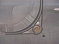 Close up of removable insert in "A" side
 -
 "B" side of die with side pull actuators
 -
 Insert removed from die


Mould design
[edit]
The mould consists of two primary components, the injection mould (A plate) and the ejector mould (B plate). These components are also referred to as moulder and mouldmaker. Plastic resin enters the mould through a sprue or gate in the injection mould; the sprue bushing is to seal tightly against the nozzle of the injection barrel of the moulding machine and to allow molten plastic to flow from the barrel into the mould, also known as the cavity.[13]: 141 The sprue bushing directs the molten plastic to the cavity images through channels that are machined into the faces of the A and B plates. These channels allow plastic to run along them, so they are referred to as runners.[13]: 142 The molten plastic flows through the runner and enters one or more specialised gates and into the cavity[19]: 15 geometry to form the desired part.

The amount of resin required to fill the sprue, runner and cavities of a mould comprises a "shot". Trapped air in the mould can escape through air vents that are ground into the parting line of the mould, or around ejector pins and slides that are slightly smaller than the holes retaining them. If the trapped air is not allowed to escape, it is compressed by the pressure of the incoming material and squeezed into the corners of the cavity, where it prevents filling and can also cause other defects. The air can even become so compressed that it ignites and burns the surrounding plastic material.[13]: 147
To allow for removal of the moulded part from the mould, the mould features must not overhang one another in the direction that the mould opens, unless parts of the mould are designed to move from between such overhangs when the mould opens using components called Lifters.[citation needed]
Sides of the part that appear parallel with the direction of draw (the axis of the cored position (hole) or insert is parallel to the up and down movement of the mould as it opens and closes)[19]: 406 are typically angled slightly, called draft, to ease release of the part from the mould. Insufficient draft can cause deformation or damage. The draft required for mould release is primarily dependent on the depth of the cavity; the deeper the cavity, the more draft necessary. Shrinkage must also be taken into account when determining the draft required.[19]: 332 If the skin is too thin, then the moulded part tends to shrink onto the cores that form while cooling and cling to those cores, or the part may warp, twist, blister or crack when the cavity is pulled away.[13]: 47
A mould is usually designed so that the moulded part reliably remains on the ejector (B) side of the mould when it opens, and draws the runner and the sprue out of the (A) side along with the parts. The part then falls freely when ejected from the (B) side. Tunnel gates, also known as submarine or mould gates, are located below the parting line or mould surface. An opening is machined into the surface of the mould on the parting line. The moulded part is cut (by the mould) from the runner system on ejection from the mould.[19]: 288 Ejector pins, also known as knockout pins, are circular pins placed in either half of the mould (usually the ejector half), which push the finished moulded product, or runner system out of a mould.[13]: 143 The ejection of the article using pins, sleeves, strippers, etc., may cause undesirable impressions or distortion, so care must be taken when designing the mould.[citation needed]
The standard method of cooling is passing a coolant (usually water) through a series of holes drilled through the mould plates and connected by hoses to form a continuous pathway. The coolant absorbs heat from the mould (which has absorbed heat from the hot plastic) and keeps the mould at a proper temperature to solidify the plastic at the most efficient rate.[13]: 86
To ease maintenance and venting, cavities and cores are divided into pieces, called inserts, and sub-assemblies, also called inserts, blocks, or chase blocks. By substituting interchangeable inserts, one mould may make several variations of the same part.[citation needed]
More complex parts are formed using more complex moulds. These may have sections called slides, that move into a cavity perpendicular to the draw direction, to form overhanging part features. When the mould is opened, the slides are pulled away from the plastic part by using stationary “angle pins” on the stationary mould half. These pins enter a slot in the slides and cause the slides to move backward when the moving half of the mould opens. The part is then ejected and the mould closes. The closing action of the mould causes the slides to move forward along the angle pins.[13]: 268
A mould can produce several copies of the same parts in a single "shot". The number of "impressions" in the mould of that part is often incorrectly referred to as cavitation. A tool with one impression is often called a single impression (cavity) mould.[20]: 398 A mould with two or more cavities of the same parts is usually called a multiple impression (cavity) mould. (Not to be confused with "Multi-shot moulding" {which is dealt with in the next section.})[20]: 262 Some extremely high production volume moulds (like those for bottle caps) can have over 128 cavities.[citation needed]
In some cases, multiple cavity tooling moulds a series of different parts in the same tool. Some toolmakers call these moulds family moulds, as all the parts are related—e.g., plastic model kits.[21]: 114
Some moulds allow previously moulded parts to be reinserted to allow a new plastic layer to form around the first part. This is often referred to as overmoulding. This system can allow for production of one-piece tires and wheels.

Moulds for highly precise and extremely small parts from micro injection molding requires extra care in the design stage, as material resins react differently compared to their full-sized counterparts where they must quickly fill these incredibly small spaces, which puts them under intense shear strains.[23]
Multi-shot moulding
[edit]

Two-shot, double-shot or multi-shot moulds are designed to "overmould" within a single moulding cycle and must be processed on specialised injection moulding machines with two or more injection units. This process is actually an injection moulding process performed twice and therefore can allow only for a much smaller margin of error. In the first step, the base colour material is moulded into a basic shape, which contains spaces for the second shot. Then the second material, a different colour, is injection-moulded into those spaces. Pushbuttons and keys, for instance, made by this process have markings that cannot wear off, and remain legible with heavy use.[13]: 174
Mould storage
[edit]Manufacturers go to great lengths to protect custom moulds due to their high average costs. The perfect temperature and humidity levels are maintained to ensure the longest possible lifespan for each custom mould. Custom moulds, such as those used for rubber injection moulding, are stored in temperature and humidity controlled environments to prevent warping.[citation needed]
Tool materials
[edit]Tool steel is often used. Mild steel, aluminium, nickel or epoxy are suitable only for prototype or very short production runs.[1] Modern hard aluminium (7075 and 2024 alloys) with proper mould design, can easily make moulds capable of 100,000 or more part life with proper mould maintenance.[24]

Machining
[edit]Moulds are built through two main methods: standard machining and EDM. Standard machining, in its conventional form, has historically been the method of building injection moulds. With technological developments, CNC machining became the predominant means of making more complex moulds with more accurate mould details in less time than traditional methods.[citation needed]
The electrical discharge machining (EDM) or spark erosion process has become widely used in mould making. As well as allowing the formation of shapes that are difficult to machine, the process allows pre-hardened moulds to be shaped so that no heat treatment is required. Changes to a hardened mould by conventional drilling and milling normally require annealing to soften the mould, followed by heat treatment to harden it again. EDM is a simple process in which a shaped electrode, usually made of copper or graphite, is very slowly lowered onto the mould surface over a period of many hours, which is immersed in paraffin oil (kerosene). A voltage applied between tool and mould causes spark erosion of the mould surface in the inverse shape of the electrode.[25]
Cost
[edit]The number of cavities incorporated into a mould directly correlate in moulding costs. Fewer cavities require far less tooling work, so limiting the number of cavities lowers initial manufacturing costs to build an injection mould.[citation needed]
As the number of cavities play a vital role in moulding costs, so does the complexity of the part's design. Complexity can be incorporated into many factors such as surface finishing, tolerance requirements, internal or external threads, fine detailing or the number of undercuts that may be incorporated.[26]
Further details, such as undercuts, or any feature that needs additional tooling, increases mould cost. Surface finish of the core and cavity of moulds further influences cost.[citation needed]
Rubber injection moulding process produces a high yield of durable products, making it the most efficient and cost-effective method of moulding. Consistent vulcanisation processes involving precise temperature control significantly reduces all waste material.[citation needed]
Injection process
[edit]
Usually, the plastic materials are formed in the shape of pellets or granules and sent from the raw material manufacturers in paper bags. With injection moulding, pre-dried granular plastic is fed by a forced ram from a hopper into a heated barrel. As the granules are slowly moved forward by a screw-type plunger, the plastic is forced into a heated chamber, where it is melted. As the plunger advances, the melted plastic is forced through a nozzle that rests against the mould, allowing it to enter the mould cavity through a gate and runner system. The mould remains cold so the plastic solidifies almost as soon as the mould is filled.[1]
Injection moulding cycle
[edit]The sequence of events during the injection mould of a plastic part is called the injection moulding cycle. The cycle begins when the mould closes, followed by the injection of the polymer into the mould cavity. Once the cavity is filled, a holding pressure is maintained to compensate for material shrinkage. In the next step, the screw turns, feeding the next shot to the front screw. This causes the screw to retract as the next shot is prepared. Once the part is sufficiently cool, the mould opens and the part is ejected.[27]: 13
Scientific versus traditional moulding
[edit]Traditionally, the injection portion of the moulding process was done at one constant pressure to fill and pack the cavity. This method, however, allowed for a large variation in dimensions from cycle-to-cycle. More commonly used now is scientific or decoupled moulding, a method pioneered by RJG Inc.[28][29][30] In this the injection of the plastic is "decoupled" into stages to allow better control of part dimensions and more cycle-to-cycle (commonly called shot-to-shot in the industry) consistency. First the cavity is filled to approximately 98% full using velocity (speed) control. Although the pressure should be sufficient to allow for the desired speed, pressure limitations during this stage are undesirable. Once the cavity is 98% full, the machine switches from velocity control to pressure control, where the cavity is "packed out" at a constant pressure, where sufficient velocity to reach desired pressures is required. This lets workers control part dimensions to within thousandths of an inch or better.[31]
Different types of injection moulding processes
[edit]

Although most injection moulding processes are covered by the conventional process description above, there are several important moulding variations including, but not limited to:
- Die casting
- Metal injection moulding
- Thin-wall injection moulding
- Injection moulding of liquid silicone rubber[27]: 17–18
- Reaction injection moulding
- Micro injection moulding
- Gas-assisted injection moulding
- Cube mold technology
- Multi-material injection molding
A more comprehensive list of injection moulding processes may be found here: [1]
Process troubleshooting
[edit]Like all industrial processes, injection molding can produce flawed parts, even in toys. In the field of injection moulding, troubleshooting is often performed by examining defective parts for specific defects and addressing these defects with the design of the mould or the characteristics of the process itself. Trials are often performed before full production runs in an effort to predict defects and determine the appropriate specifications to use in the injection process.[3]: 180
When filling a new or unfamiliar mould for the first time, where shot size for that mould is unknown, a technician/tool setter may perform a trial run before a full production run. They start with a small shot weight and fills gradually until the mould is 95 to 99% full. Once they achieve this, they apply a small amount of holding pressure and increase holding time until gate freeze off (solidification time) has occurred. Gate freeze off time can be determined by increasing the hold time, and then weighing the part. When the weight of the part does not change, the gate has frozen and no more material is injected into the part. Gate solidification time is important, as this determines cycle time and the quality and consistency of the product, which itself is an important issue in the economics of the production process.[32] Holding pressure is increased until the parts are free of sinks and part weight has been achieved.[citation needed]
Moulding defects
[edit]Injection moulding is a complex technology with possible production problems. They can be caused either by defects in the moulds, or more often by the moulding process itself.[3]: 47–85
| Moulding defects | Alternative name | Descriptions | Causes |
|---|---|---|---|
| Blister | Blistering | Raised or layered zone on surface of the part | Tool or material is too hot, often caused by a lack of cooling around the tool or a faulty heater. |
| Burn marks | Air burn/gas burn/dieseling/gas marks/Blow marks | Black or brown burnt areas on the part located at furthest points from gate or where air is trapped | Tool lacks venting, injection speed is too high. |
| Colour streaks | Localised change of colour | Masterbatch isn't mixing properly, or the material has run out and it's starting to come through as natural only. Previous coloured material "dragging" in nozzle or check valve. | |
| Contamination | Unwanted or foreign material | Different colour matter seen in product, weakening the product | Poor material introduced by bad recycling or regrind policy; may include floor sweepings, dust and debris. |
| Delamination | Thin mica like layers formed in part wall | Contamination of the material e.g. PP mixed with ABS, very dangerous if the part is being used for a safety critical application as the material has very little strength when delaminated as the materials cannot bond. | |
| Flash | Excess material in thin layer exceeding normal part geometry | Mould is over packed or parting line on the tool is damaged, too much injection speed/material injected, clamping force too low. Can also be caused by dirt and contaminants around tooling surfaces. | |
| Embedded contaminates | Embedded particulates | Foreign particle (burnt material or other) embedded in the part | Particles on the tool surface, contaminated material or foreign debris in the barrel, or too much shear heat burning the material prior to injection. |
| Flow marks | Flow lines | Directionally "off tone" wavy lines or patterns | Injection speeds too slow (the plastic has cooled down too much during injection, injection speeds should be set as fast as is appropriate for the process and material used). |
| Gate Blush | Halo or Blush Marks | Circular pattern around gate, normally only an issue on hot runner molds | Injection speed is too fast, gate/sprue/runner size is too small, or the melt/mold temp is too low. |
| Jetting | Jetting is a snake-like stream which occurs when polymer melt is pushed at a high velocity through restrictive areas. | Poor tool design, gate position or runner. Injection speed set too high. Poor design of gates, which causes too little die swell and result jetting. | |
| Knit lines | Weld lines | Small lines on the backside of core pins or windows in parts that look like just lines. | Caused by the melt-front flowing around an object standing proud in a plastic part as well as at the end of fill where the melt-front comes together again. Can be minimised or eliminated with a mould-flow study when the mould is in design phase. Once the mould is made and the gate is placed, one can minimise this flaw only by changing the melt and the mould temperature. |
| Polymer degradation | Polymer breakdown from hydrolysis, oxidation etc. | Excess water in the granules, excessive temperatures in barrel, excessive screw speeds causing high shear heat, material being allowed to sit in the barrel for too long, too much regrind being used. | |
| Sink marks | Sinks | Localised depression (In thicker zones) | Holding time/pressure too low, cooling time too short, with sprueless hot runners this can also be caused by the gate temperature being set too high. Excessive material or walls too thick. |
| Short shot | Short fill, nonfill, or short mould | Partial part | Lack of material, injection speed or pressure too low, mould too cold, lack of gas vents. |
| Splay marks | Splash mark or silver streaks | Usually appears as silver streaks along the flow pattern, however depending on the type and colour of material it may represent as small bubbles caused by trapped moisture. | Moisture in the material, usually when hygroscopic resins are dried improperly. Trapping of gas in "rib" areas due to excessive injection velocity in these areas. Material too hot, or is being sheared too much. |
| Stringiness | Stringing or long-gate | String like remnant from previous shot transfer in new shot | Nozzle temperature too high. Gate hasn't frozen off, no decompression of the screw, no sprue break, poor placement of the heater bands inside the tool. |
| Voids | Empty space within part (air pocket is commonly used) | Lack of holding pressure (holding pressure is used to pack out the part during the holding time). Filling too fast, not allowing the edges of the part to set up. Also mould may be out of registration (when the two halves don't centre properly and part walls are not the same thickness). The provided information is the common understanding, Correction: The Lack of pack (not holding) pressure (pack pressure is used to pack out even though is the part during the holding time). Filling too fast does not cause this condition, as a void is a sink that did not have a place to happen. In other words, as the part shrinks the resin separated from itself as there was not sufficient resin in the cavity. The void could happen at any area or the part is not limited by the thickness but by the resin flow and thermal conductivity, but it is more likely to happen at thicker areas like ribs or bosses. Additional root causes for voids are un-melt on the melt pool. | |
| Weld line | Knit line / Meld line / Transfer line | Discoloured line where two flow fronts meet | Mould or material temperatures set too low (the material is cold when they meet, so they don't bond). Time for transition between injection and transfer (to packing and holding) is too early. |
| Warping | Twisting | Distorted part | Cooling is too short, material is too hot, lack of cooling around the tool, incorrect water temperatures (the parts bow inwards towards the hot side of the tool) Uneven shrinking between areas of the part. |
| Cracks | Crazing | Improper fusion of two fluid flows, a state before weld line. | Threadline gap in-between part due to improper gate location in complex design parts including excess of holes (multipoint gates to be provided), process optimization, proper air venting. |
Methods such as industrial CT scanning can help with finding these defects externally as well as internally.[citation needed][33]
From the table above we know that optimizing the injection molding setup for new products is usually time-consuming and labor-intensive in real production. In recent years, some experts have introduced a reinforcement learning method based on the "actor-critic" algorithm to improve efficiency. This approach enables faster, more efficient parameter tuning and supports self-adjusting molding systems.[34]
Tolerances
[edit]Tolerance depends on the dimensions of the part. An example of a standard tolerance for a 1-inch dimension of an LDPE part with 0.125 inch wall thickness is +/- 0.008 inch (0.2 mm).[19]: 446
Power requirements
[edit]The power required for this process of injection moulding depends on many things and varies between materials used. Manufacturing Processes Reference Guide states that the power requirements depend on "a material's specific gravity, melting point, thermal conductivity, part size, and molding rate." Below is a table from page 243 of the same reference as previously mentioned that best illustrates the characteristics relevant to the power required for the most commonly used materials.
| Material | Specific gravity[clarification needed] | Melting point (°F) | Melting point (°C) |
|---|---|---|---|
| Epoxy | 1.12 to 1.24 | 248 | 120 |
| Phenolic | 1.34 to 1.95 | 248 | 120 |
| Nylon | 1.01 to 1.15 | 381 to 509 | 194 to 265 |
| Polyethylene | 0.91 to 0.965 | 230 to 243 | 110 to 117 |
| Polystyrene | 1.04 to 1.07 | 338 | 170 |
Robotic moulding
[edit]Automation means that the smaller size of parts permits a mobile inspection system to examine multiple parts more quickly. In addition to mounting inspection systems on automatic devices, multiple-axis robots can remove parts from the mould and position them for further processes.[35]
Specific instances include removing of parts from the mould immediately after the parts are created, as well as applying machine vision systems. A robot grips the part after the ejector pins have been extended to free the part from the mould. It then moves them into either a holding location or directly onto an inspection system. The choice depends upon the type of product, as well as the general layout of the manufacturing equipment. Vision systems mounted on robots have greatly enhanced quality control for insert moulded parts. A mobile robot can more precisely determine the placement accuracy of the metal component, and inspect faster than a human can.[35]
Gallery
[edit]-
 Lego injection mould, lower side
 -
 Lego injection mould, detail of lower side
 -
 Lego injection mould, upper side
 -
 Lego injection mould, detail of upper side


See also
[edit]- Craft
- Design of plastic components
- Direct injection expanded foam molding
- Extrusion moulding
- Fusible core injection moulding
- Gravimetric blender
- Hobby injection moulding
- Injection mould construction
- Matrix moulding
- Multi-material injection moulding
- Rapid Heat Cycle Molding
- Reaction injection moulding
- Rotational moulding
- Urethane casting
- Hot runner
References
[edit]- ^ a b c d e f Todd, Robert H.; Allen, Dell K.; Alting, Leo (1994). Manufacturing Processes Reference Guide. Industrial Press, Inc.
- ^ "Application Overview: Injection Molding". Yaskawa America, Inc. Archived from the original on 2006-04-12. Retrieved 2009-02-27.
- ^ a b c d e f g h i Malloy, Robert A. (1994). Plastic Part Design for Injection Molding. Munich Vienna New York: Hanser.
- ^ "Design Guide: Injection Molding" (PDF). Xometry. Archived (PDF) from the original on 2018-01-19.
- ^ "Injection Molding Archived 2016-05-08 at the Wayback Machine", Meridian Products Corporation, Retrieved April 26, 2016.
- ^ Langton, Vanessa D. (11 March 2015). "Candle Making Like a Pro: A Complete Guide on How to Make Perfect Candles at Home for Fun & Profit".
- ^ White, James Lindsay (16 January 1991). Principles of Polymer Engineering Rheology. John Wiley & Sons. ISBN 9780471853626.
- ^ U.S. patent 133,229, dated 19 November 1872.
- ^ Meade, Richard Kidder; McCormack, Harry; Clark, Laurance T.; Sclater, Alexander G.; Lamborn, Lloyd (27 April 2018). "Chemical Age". McCready Publishing Company. Retrieved 27 April 2018 – via Google Books.
- ^ "About Injection Molding". Xcentric Mold & Engineering, Inc. Archived from the original on 22 November 2012. Retrieved 30 January 2013.
- ^ Merril, Arthur M. (1955). Plastics Technology, Volume 1. Rubber/Automotive Division of Hartman Communications, Incorporated, 1955.
- ^ Torr, James (11 April 2010). "A Short History of Injection Moulding". AV Plastics Injection Moulding - Get Stuff Made. Archived from the original on 24 May 2018. Retrieved 23 May 2018.
- ^ a b c d e f g h i j k Bryce, Douglas M. (1996). Plastic Injection Molding: Manufacturing Process Fundamentals. SME.
- ^ a b "Injection Molding". custompart.net. CustomPartNet. Archived from the original on 2016-03-01.
- ^ "Injection Molding Applications". Engineer's Edge: Solutions by Design. Engineers Edge, LLC. Archived from the original on 20 August 2013. Retrieved 30 January 2013.
- ^ Group®, The Rodon (10 August 2022). "5 Common Plastic Resins Used in Injection Molding". www.rodongroup.com.
- ^ "Suspended". Medium. Archived from the original on 24 March 2018. Retrieved 27 April 2018.
- ^ a b Rosato, Donald V.; Rosato, Marlene G. (2000). Concise Encyclopedia of Plastics. Springer.
- ^ a b c d e Rosato, Dominick; Rosato, Marlene; Rosato, Donald (2000). Injection Molding Handbook (3rd ed.). Kluwer Academic Publishers.
- ^ a b Whelan, Tony (1994). Polymer Technology Dictionary. Springer.
- ^ Rees, Herbert; Catoen, Bruce (2006). Selecting Injection Molds – Weighing Cost versus Productivity. Hanser Publishers.
- ^ "Micro Systems". Micro Systems. Retrieved 3 Nov 2023.
- ^ "Micro Moulding vs Conventional Moulding". Micro Systems. 16 May 2023. Retrieved 22 May 2023.
- ^ Goldsberry, Clare (29 August 2012). "Aluminum vs. steel tooling: Which material is right, and how to design and maintain?". Plastics Today. UBM Canon. Archived from the original on 2012-09-02.
- ^ "Die Casting". Advantage Tool and Manufacturing. Archived from the original on 2009-05-20.
- ^ "Plastic Injection Molding – Xcentric Mold & Engineering". xcentricmold.com. Archived from the original on 7 July 2017. Retrieved 27 April 2018.
- ^ a b Injection Molding Handbook (2nd ed.).
- ^ "Almanac: The fundamentals of Decoupled Molding". Plastics Today. June 2005. Archived from the original on 2 April 2015. Retrieved 16 January 2015.
- ^ "Implementing Decoupled Molding". Paulson Training Programs. Archived from the original on 9 January 2015. Retrieved 16 January 2015.
- ^ "Injection Molding Guide" (PDF). Lubrizol. p. 6. Archived from the original (PDF) on 15 July 2014. Retrieved 16 January 2015.
- ^ "Decoupled Molding(SM)". Plastics Net. Archived from the original on 29 May 2015. Retrieved 14 January 2015.
- ^ Pantani, R.; De Santis, F.; Brucato, V.; Titomanlio, G. (2004). Analysis of Gate Freeze-Off Time in Injection Molding. Polymer Engineering and Science.
- ^ Jennifer M. Sietins, William H. Green, Justin S. Jones. "Material Evaluation Using X-ray Computed Tomography" (PDF). NASA Technical Reports Server.
{{cite web}}: CS1 maint: multiple names: authors list (link) - ^ Richárd Dominik Párizs, Dániel Török. "Optimizing Injection Molding Parameters Using Reinforcement Learning with Prior Knowledge". TonZa Making.
- ^ a b Callister, William D. (2003). Materials Science and Engineering: An Introduction. John Wiley and Sons. ISBN 9780471135760.
Further reading
[edit]- Lindsay, John A. (2012). Practical guide to rubber injection moulding (Online-Ausg. ed.). Shawbury, Shrewsbury, Shropshire, UK: Smithers Rapra. ISBN 978-1847357083.
External links
[edit]- Shrinkage and Warpage – Santa Clara University Engineering Design Center Archived 2020-05-30 at the Wayback Machine


| International | |
|---|---|
| National | |
| Other | |
Injection moulding
View on GrokipediaOverview
Definition and basic principles
Injection molding is a manufacturing process used to produce parts by heating thermoplastic or thermoset materials to a molten state, injecting the material into a mold cavity under high pressure, allowing it to cool and solidify, and then ejecting the finished part from the mold.[11] This method enables the creation of precise, repeatable components with intricate details, making it a cornerstone of mass production in industries ranging from automotive to consumer goods.[10] The basic principles of injection molding revolve around the rheological behavior of the molten material, particularly its viscosity and shear-thinning characteristics, which allow the fluid to flow easily under high shear rates during injection while solidifying upon cooling.[12] The process unfolds in distinct phases: filling, where the molten material is forced into the mold cavity to replicate the desired shape; packing, which applies additional pressure to compensate for material shrinkage and ensure complete cavity filling; cooling, during which the part solidifies as heat transfers to the mold; and ejection, where the cooled part is removed for the cycle to repeat.[13] Critical parameters such as injection pressure, melt temperature, and cycle time govern these phases, influencing flow dynamics, part density, and dimensional accuracy to form precise geometries without defects.[14] Material injection volume is precisely controlled through the volumetric flow rate of the screw mechanism, expressed as where is the flow rate, is the screw diameter, and is the screw speed; this equation highlights how machine settings directly dictate the rate at which molten material enters the mold.[15] The process is ideally suited for high-volume production of complex geometries, such as gears, housings, and consumer product components, due to its efficiency in replicating detailed designs at scale while minimizing per-unit costs after initial tooling investment.[11]Advantages and limitations
Injection moulding offers several key advantages that make it a preferred method for high-volume production of plastic parts. It enables high production rates, often reaching thousands of parts per hour, which supports efficient mass manufacturing.[16] The process provides precision for intricate designs, achieving tolerances as tight as ±0.1 mm, allowing for complex geometries with consistent quality and minimal post-processing needs.[17] Material efficiency is another benefit, as the process generates minimal waste through precise control of the melt and mold filling, while automation reduces labor costs significantly.[18] Despite these strengths, injection moulding has notable limitations. The high initial tooling costs for molds typically range from $10,000 to $100,000 or more, depending on complexity and material, making it economically unviable for very low production volumes.[19] Lead times for mold fabrication can extend from weeks to months, delaying project timelines.[10] Additionally, the process poses challenges with material degradation, as high temperatures during melting and injection can cause thermal breakdown in sensitive polymers if residence times are excessive.[20] Compared to alternatives, injection moulding is faster for producing complex plastic parts than die casting, which is primarily suited for metals, though it requires higher upfront investment than extrusion for simple, continuous shapes.[21] [22] From an environmental perspective, injection moulding supports recyclability of thermoplastics through reprocessing, but the repeated heating and cooling cycles make it energy-intensive overall.[23] [24]History
Early development
The origins of injection moulding can be traced to the late 19th century, driven by the need for synthetic alternatives to scarce natural materials like ivory. In 1868, American inventors John Wesley Hyatt and his brother Isaiah Hyatt experimented with cellulose nitrate, blending it with camphor to create celluloid, the first commercially viable semi-synthetic plastic, primarily for manufacturing billiard balls as an ivory substitute. This material's moldability laid the groundwork for injection processes, addressing the limitations of earlier plastics like Parkesine, which had proven too unstable for widespread use.[25] In 1868, John Wesley Hyatt received U.S. Patent No. 50,359 for producing billiard balls from celluloid, but more significantly, he and his brother patented the first injection moulding machine (U.S. Patent No. 133,229)—a simple plunger-based device that heated celluloid and forced it into a mold under pressure. This machine marked the birth of injection moulding as a distinct manufacturing technique, enabling the production of small, precise items like combs and buttons, though early operations remained largely manual and labor-intensive.[3][26] The early 20th century brought transformative material innovations with Leo Hendrik Baekeland's invention of Bakelite in 1907, the world's first fully synthetic plastic—a thermosetting phenolic resin formed from phenol and formaldehyde under heat and pressure. Patented in 1907 (U.S. Patent No. 942,699), Bakelite's heat resistance and electrical insulating properties made it ideal for industrial applications, spurring the development of semi-automatic injection machines in the 1920s for mass-producing electrical components such as insulators and switches. In 1919, German chemist Arthur Eichengrün developed the first injection molding press, enabling more efficient production using plasticized cellulose acetate.[27][3] Key milestones in the 1930s included the adoption of hydraulic systems in injection machines, which replaced manual plungers with powered rams for greater force and consistency, allowing larger and more complex parts like automotive dashboard components. During World War II, the demand for rapid, cost-effective production surged, with injection moulding enabling mass fabrication of military parts, including gun triggers, shell casings, and other non-structural components that leveraged plastics' lightweight durability. However, initial challenges persisted, including the brittleness and flammability of early thermoplastics like celluloid, which degraded over time, and the limitations of manual and semi-automatic operations that restricted output and precision.[28][29][4]Modern advancements
In the post-World War II era, injection molding underwent significant technological shifts beginning in the 1950s, with the adoption of screw-type injectors replacing traditional plunger mechanisms, which improved melt homogeneity and consistency in polymer processing.[25] This innovation, pioneered by James Watson Hendry in 1946 and widely implemented in the following decade, allowed for more uniform material distribution and reduced defects in molded parts.[3] By the 1970s, the integration of microprocessor controls further enhanced precision, enabling automated regulation of parameters such as temperature, pressure, and injection speed, as exemplified by the first such machine introduced by ARBURG in 1975.[30] The 1980s and 1990s marked a digital transformation in mold design through the widespread use of computer-aided design (CAD) and computer-aided manufacturing (CAM) systems, which streamlined workflows and reduced lead times for mold development by over 50% compared to manual methods.[31] This period also saw the early adoption of computer-aided engineering (CAE) tools, with companies like Moldflow pioneering simulation software in the early 1980s to model melt flow, pressure drops, and temperature variations, facilitating proactive design adjustments.[32] Concurrently, gas-assisted injection molding emerged commercially in the early 1980s, with patents like those from the late 1970s enabling the injection of gas to create hollow sections, thereby minimizing material use and warping in complex parts.[33] Multi-material molding techniques also advanced during this period, supported by patents such as US4315724A in 1982, which facilitated the sequential injection of different polymers for multi-color or multi-property components in a single cycle.[34] From the 2010s onward, injection molding has increasingly incorporated Industry 4.0 principles, with IoT-enabled sensors providing real-time monitoring of process variables like cavity pressure and temperature to optimize quality and predict maintenance needs.[35] This era has also seen the integration of artificial intelligence (AI) and big data analytics for process optimization and quality control, utilizing machine learning methods to analyze industrial data and enable on-line parameter adjustments for improved production efficiency and reduced defects.[36] Furthermore, advancements in multi-physics coupling simulations have enhanced mold design and prediction by integrating filling, structural, and thermal analyses, allowing for accurate modeling of mold deflections and part performance to minimize issues like flashing and optimize tool economics.[37] Sustainability efforts have driven the adoption of bio-based polymers, such as polylactic acid (PLA) derived from renewable sources like corn starch, which offer biodegradability while maintaining compatibility with standard injection processes.[38] Hybrid electric-hydraulic machines have become prevalent, combining the precision of electric drives with hydraulic power for clamping, achieving energy efficiency improvements of up to 60% over fully hydraulic systems through servo-controlled pumps that minimize idle power consumption.[39] These machines also support brief integration with robotic systems for automated part handling, enhancing overall production throughput.[40] A notable recent milestone occurred in 2023, when advancements in micro-injection molding enabled the production of sub-millimeter features with tolerances below 10 microns, particularly for intricate electronic components like connectors and sensors in consumer devices.[41]Materials
Suitable polymers
Injection moulding primarily utilizes thermoplastics, which soften when heated and solidify upon cooling, allowing for repeated melting and reshaping without chemical alteration. Common thermoplastics include polyethylene (PE), polypropylene (PP), acrylonitrile butadiene styrene (ABS), polystyrene (PS), and nylon (polyamide, PA). These materials are selected for their ability to flow into molds under pressure at elevated temperatures, typically exhibiting a melt flow index (MFI) ranging from 1 to 100 g/10 min, which indicates their viscosity and ease of processing—lower MFI values suit thicker parts, while higher values (e.g., 10–30 g/10 min) enable filling complex geometries.[42][43] The crystallinity of these polymers significantly influences dimensional stability during cooling, with semi-crystalline types like PE and PP experiencing higher shrinkage rates of 1–3% due to molecular reorganization, compared to 0.4–0.8% for amorphous polymers such as ABS and PS. For instance, high-density polyethylene (HDPE) has a shrinkage of 1.5–2.5%, PP ranges from 1.0–2.5%, ABS from 0.7–1.6%, PS from 0.4–0.7%, and nylon from 0.7–2.0%, varying with moisture content. Processing occurs at 180–300°C, where viscosity must be low enough for uniform flow but stable to prevent degradation; PP, for example, processes at 180–280°C with good thermal stability up to 300°C. Polymer costs vary significantly depending on the type, grade, and performance requirements. Commodity polymers such as PE, PP, PS, and ABS typically range from $1 to $5 per kg, making them economical for high-volume production. Engineering polymers, including nylon (PA), polycarbonate (PC), and polyoxymethylene (POM), generally cost $3 to $20 per kg, providing enhanced mechanical and thermal properties for more demanding applications. High-performance polymers such as polyether ether ketone (PEEK), polyetherimide (PEI), and polyphenylene sulfide (PPS) can range from $20 to over $100 per kg, justified in environments requiring exceptional heat, chemical, or mechanical resistance. Material selection directly impacts production economics: higher-cost polymers increase raw material expenses per part, while reinforced grades (e.g., glass-filled nylon) can accelerate tooling wear due to abrasiveness, potentially raising mold maintenance costs, influencing cycle times, and affecting overall unit costs. Thermoplastics are highly recyclable, as scrap can be remelted and reprocessed multiple times with minimal property loss, supporting sustainable manufacturing. Additionally, sustainable designs increasingly incorporate biodegradable thermoplastics such as polylactic acid (PLA) and polyhydroxyalkanoates (PHA), derived from renewable resources like corn starch or bacterial fermentation. These materials biodegrade under composting conditions, reducing long-term environmental impact and fossil fuel dependency. PLA, for instance, processes at 170–230°C with a typical MFI of 10–35 g/10 min and shrinkage of 0.3–0.8%, making it suitable for injection molding in applications like packaging and disposable medical devices, though it requires industrial composting for effective degradation.[44][45][46][47][48][19][49][50][51][52]| Polymer | Crystallinity | MFI Range (g/10 min) | Shrinkage (%) | Processing Temp (°C) | Cost ($/kg) | Key Properties & Examples |
|---|---|---|---|---|---|---|
| Polyethylene (PE) | Semi-crystalline | 0.1–50 | 1.5–3.0 | 180–260 | 1–2.5 | Flexible, chemical-resistant; used in bottles and containers.[53][48] |
| Polypropylene (PP) | Semi-crystalline | 1–100 | 1.0–2.5 | 180–280 | 1–3.5 | Impact-resistant, fatigue-enduring; ideal for automotive bumpers.[54][55][56] |
| ABS | Amorphous | 1–30 | 0.7–1.6 | 220–260 | 1.5–4.5 | Rigid, tough; employed in LEGO bricks for durability.[57][58] |
| Polystyrene (PS) | Amorphous | 5–50 | 0.4–0.8 | 180–240 | 1–3 | Clear, brittle; suitable for disposable cutlery and packaging.[59] |
| Nylon (PA) | Semi-crystalline | 1–100 | 0.7–2.0 | 250–300 | 2.5–7 | Strong, wear-resistant; applied in gears and fasteners.[56][44] |
| Polycarbonate (PC) | Amorphous | 5–60 | 0.7–1.0 | 260–320 | 2.5–5 | High impact resistance, transparent; used in lenses and housings.[48][44] |
| Polyoxymethylene (POM) | Semi-crystalline | 1–50 | 1.8–2.5 | 180–230 | 2.5–4.5 | Low friction, high stiffness; gears, bearings.[48][44] |
| Polyether ether ketone (PEEK) | Semi-crystalline | 1–30 | 1.2–1.5 | 340–400 | 50–130 | Exceptional heat and chemical resistance; aerospace, medical applications.[47][44] |
| Polylactic Acid (PLA) | Semi-crystalline | 10–35 | 0.3–0.8 | 170–230 | 2–10 | Biodegradable, stiff, transparent; used in sustainable packaging and disposables.[50][45][52][60] |
Additives and reinforcements
Additives and reinforcements are incorporated into base polymers during injection moulding to enhance specific properties such as stability, aesthetics, flexibility, strength, and functionality, allowing for tailored performance in end-use applications.[65] These modifications are achieved by blending small quantities of additives or higher loadings of reinforcements into the molten polymer prior to injection, which influences the material's rheology, mechanical behavior, and processing characteristics.[66] Stabilizers, including antioxidants, are added to prevent degradation from oxidation during processing and service life; for instance, they inhibit chain scission and discoloration in polyolefins exposed to heat and oxygen.[65] Colorants, typically pigments at loadings of 0.1–5% by weight, provide aesthetic appeal and UV opacity while maintaining transparency or opacity as needed. Plasticizers, such as phthalates in polyvinyl chloride (PVC), improve flexibility and processability by reducing melt viscosity and increasing chain mobility, enabling the production of softer, more ductile parts.[66] Reinforcements like glass fibers are commonly loaded at 10–40% by weight to boost tensile strength, potentially reaching up to 100 MPa in reinforced thermoplastics such as polycarbonate composites.[67] Carbon nanotubes (CNTs), often at lower loadings of 1–5%, impart electrical conductivity to otherwise insulating polymers, enabling applications in electrostatic dissipation.[68] However, these reinforcements increase melt viscosity, which can complicate flow during injection, and contribute to anisotropic warpage due to differential shrinkage along fiber orientations.[69] Fillers, such as mineral fillers, often reduce material costs by diluting the polymer with cheaper substances and minimize volumetric shrinkage for better dimensional control. Reinforcements, such as glass fibers, typically increase material costs slightly compared to the unfilled base polymer but provide significant enhancements in mechanical properties. However, abrasive fillers and reinforcements accelerate equipment wear through interactions with screws, barrels, and molds; in particular, glass fiber reinforcements significantly increase tooling wear due to abrasion, leading to higher maintenance costs and affecting long-term production economics and material selection trade-offs.[47][70] In fiber-reinforced composites, the orientation factor , which quantifies directional stiffness, is given by where is the angle between the fiber axis and the loading direction; this factor highlights the anisotropy in mechanical properties arising from flow-induced alignment during moulding.[71] Representative examples include flame-retardant additives, such as halogen-free compounds in acrylonitrile butadiene styrene (ABS) for electronics housings, which achieve UL 94 V-0 ratings by promoting char formation and gas dilution to suppress ignition.[72] UV stabilizers, like hindered amine light stabilizers in polycarbonate for outdoor components, absorb or quench ultraviolet radiation to prevent photodegradation and maintain clarity over extended exposure.[73]Equipment and Tooling
Injection molding machines
Injection molding machines are specialized equipment designed to melt and inject thermoplastic or thermoset materials into molds under high pressure. They are categorized primarily by their drive systems: hydraulic, electric, and hybrid. Hydraulic machines utilize fluid power to generate substantial clamping forces, typically ranging from 50 to 5000 tons, making them suitable for large-scale production of robust parts.[74] These machines excel in applications requiring high force but consume more energy due to continuous hydraulic pumping. Electric machines, driven by servo motors, offer superior precision in speed and position control, along with energy efficiency by activating only during necessary operations; they are ideal for small to medium-sized parts demanding tight tolerances.[75] Hybrid machines integrate hydraulic clamping for high force with electric injection for accuracy, balancing speed, energy savings, and robustness in versatile manufacturing scenarios.[76] The core components of an injection molding machine include the injection unit, clamping unit, and control systems. The injection unit consists of a hopper for material feed, a heated barrel, and a reciprocating screw that melts and conveys the polymer through shear heat and conduction; this assembly plasticizes the material and injects it into the mold at pressures up to 2000 bar.[75] The clamping unit, which secures the mold during injection, employs either a toggle mechanism for rapid opening and closing or direct hydraulic actuation for consistent force application, ensuring the mold withstands internal pressures without parting.[77] Control systems, typically programmable logic controllers (PLCs), monitor and regulate parameters such as barrel temperature, injection speed, and clamping pressure via sensors and user interfaces, enabling automated cycle optimization and fault detection.[77] Machine capacities vary widely to accommodate diverse part sizes and production needs. Shot sizes, representing the maximum injectable material volume, generally range from 10 g for micro-molding to 10,000 g for large components, determined by the screw diameter and stroke length.[78] Clamping forces are specified in tons and must exceed the force generated by molten material pressure on the mold's projected area to prevent flash or defects. The required clamping force is calculated as , where is the average cavity pressure (often 400–1400 bar) and is the projected area of the part in the mold plane (in cm²), with a safety factor of 1.1–1.5 typically applied.[79] For instance, a part with a 100 cm² projected area at 600 bar requires 60 tons of force before safety adjustments.[79] Safety features are integral to injection molding machines to mitigate risks from high pressures, hot surfaces, and moving parts. Protective guards and barriers enclose hazardous areas like the clamping zone, often equipped with interlocks that halt operations if breached.[80] Emergency stop buttons, prominently placed on control panels, immediately cut power to all machine functions upon activation.[74] Maintenance practices include regular monitoring of screw and barrel wear through dimensional inspections and performance tests, as abrasion from fillers can degrade injection efficiency over time; lubrication of moving parts and hydraulic fluid checks are also routine to ensure longevity.[81]Mold design and components
Mold design in injection molding involves engineering the tool to precisely form parts by accommodating material flow, cooling, and ejection while minimizing defects and optimizing cycle times. The mold typically consists of two main halves—a stationary cavity side and a movable core side—that close to create the part geometry. Core and cavity inserts form the negative shape of the part, allowing for interchangeable components to produce variations or facilitate maintenance. Modern advancements include the use of 3D-printed inserts, which allow for rapid prototyping of complex geometries and reduce lead times compared to traditional machining.[82][83][84] Leader pins and bushings ensure precise alignment between the core and cavity halves during closing, preventing misalignment that could cause flash or incomplete fills. Ejector pins, positioned in non-aesthetic areas such as behind ribs or at runner ends, push the solidified part out of the mold after cooling. The parting line, where the two mold halves meet, defines the boundary for part separation and influences gate placement to avoid visible marks on the final product.[85][86][87] Gates control the entry of molten polymer into the cavity; common types include edge gates at the parting line for straightforward filling, submarine (tunnel) gates that shear automatically upon ejection for hidden scars, and fan gates that distribute material broadly to reduce shear stress in larger areas. Runners channel material from the sprue to the gates: cold runners solidify with each cycle and are trimmed as waste, suitable for lower volumes, while hot runners maintain melt temperature via heating elements, enabling faster cycles and reduced material waste in high-volume production. Advanced hot runner systems incorporate variable mold temperature control, which improves surface gloss and part strength by ensuring temperature uniformity and reducing polymer degradation.[88][89][90][91] Cooling channels, traditionally drilled into the mold plates, circulate coolant to extract heat efficiently; however, conformal cooling channels, which follow the contours of the part geometry and are often designed using topology optimization techniques, provide more uniform cooling, reduce cycle times, and minimize defects such as warpage. Baffles divide channels to direct flow around cores, and spiral designs promote turbulent flow for uniform temperature distribution across cylindrical or complex geometries. Draft angles of 0.5° to 2° on vertical walls facilitate part ejection by compensating for shrinkage and reducing friction, with shallower angles for polished surfaces and steeper for textured ones. Multi-cavity molds, containing up to 128 identical cavities, boost throughput for high-volume parts like closures, though they demand balanced runner systems to ensure uniform filling across all cavities.[92][93][94][95] Simulation tools like Autodesk Moldflow analyze melt flow to predict fill times, pressure distribution, and potential weld lines where flow fronts merge, allowing designers to optimize gate locations and runner sizes before fabrication. These tools also support lifecycle optimization techniques, such as predictive maintenance and material selection strategies, to extend mold lifespan and enhance overall efficiency. Cooling time, a dominant factor in cycle duration, can be estimated using the one-dimensional heat conduction equation for a slab: where is cooling time, is part thickness, is thermal diffusivity, is initial melt temperature, is mold wall temperature, and is ejection temperature. This formula assumes Newtonian cooling and infinite plate geometry, providing a baseline for design iterations.[96][97][98][99]Tool materials and fabrication
Tool steels are the primary materials used for constructing durable injection molds due to their balance of hardness, toughness, and wear resistance. P20 steel, a pre-hardened low-alloy variant, is widely selected for medium-volume production molds because of its good machinability and cost-effectiveness, typically achieving a hardness of 28-36 HRC without additional heat treatment.[100][101] For high-volume applications requiring greater durability, H13 tool steel is preferred, offering superior hot hardness and resistance to thermal fatigue at 45-52 HRC after heat treatment, enabling it to withstand abrasive resins and extended use.[102][103] Aluminum alloys, such as 7075, serve as a lower-cost alternative for prototype and low-volume molds, prized for their excellent thermal conductivity and rapid machinability, though their softer nature limits lifespan to 2,000-10,000 cycles compared to steel's longer endurance.[104][105] Beryllium-copper alloys are employed for specific components like cores and inserts where high thermal conductivity—up to six times that of tool steel—is essential for efficient cooling and reduced cycle times, providing strength comparable to hardened steels while minimizing hotspots.[106][107] Fabrication of these tools begins with CNC milling to shape the bulk mold from blocks of selected material, allowing precise contouring of cavities and cores with tolerances down to 0.01 mm.[108] For intricate geometries or undercuts that milling cannot reach, electrical discharge machining (EDM) is utilized to erode material via controlled sparks, achieving fine details without mechanical stress on hardened steels.[109] Post-machining, surface treatments such as hard chrome plating are applied to enhance wear resistance and release properties, depositing a 0.025-0.05 mm layer that increases hardness to over 65 HRC and reduces friction.[110][111] Cost considerations in tool fabrication are dominated by material selection and mold complexity, with single-cavity prototypes in aluminum costing $2,000-5,000 versus $20,000+ for multi-cavity steel family tools.[19] Tool steel prices range from $3-5 per kg for P20 and H13, significantly higher than aluminum's $2-3 per kg, influencing choices for production scale.[112] Mold lifecycle—typically 300,000-500,000 cycles for P20 and up to 1 million for H13—directly impacts amortization, as higher-end materials extend usability but elevate upfront expenses, often comprising 50-70% of total project costs with machine time accounting for 15-25%.[113][114][115] Recent advancements include 3D-printed molds for rapid prototyping, using metal additive manufacturing to produce complex cooling channels and reduce lead times to days.[116][117]Injection Process
Cycle stages
The injection moulding cycle consists of a series of sequential stages that repeat to produce parts efficiently, typically controlled by the machine's hydraulic or electric actuators. These stages ensure the molten polymer is properly introduced, formed, solidified, and removed from the mold, with the entire process optimized for high-volume production. The cycle begins with the clamping stage, where the mold halves are closed and clamped together under high force to withstand the upcoming injection pressure. This closure is achieved using the machine's clamping unit, which applies tonnage ranging from hundreds to thousands of tons depending on part size. Next is the injection stage, during which molten plastic is injected into the mold cavity at high speed and pressure, typically 50–150 MPa, to fill the cavity completely. The polymer, plasticized in the barrel, is forced through the nozzle and runner system by the advancing screw or plunger. The injection time can be calculated using the formula , where is the injection time, is the volume of the part and runners, and is the volumetric flow rate determined by screw speed and barrel dimensions. Following injection, the dwell or packing stage maintains additional pressure on the molten material to compensate for shrinkage as it begins to cool and solidify. This holding pressure, often slightly lower than injection pressure, ensures dense packing and minimizes voids, lasting a few seconds until the gate freezes. The cooling stage then dominates the cycle, where the part solidifies within the mold, typically lasting 10–50 seconds depending on material, part thickness, and mold temperature. Heat is extracted through the mold's cooling channels, with thinner walls allowing faster cooling and shorter times. During this phase, the screw rotates in the barrel to plasticize the next shot of material, a recovery process that prepares for the subsequent cycle without interrupting production.[118] Finally, the ejection stage opens the mold and removes the solidified part using ejector pins or other mechanisms integrated into the mold design. The mold then re-clamps to start the next cycle. The total cycle time ranges from 15 to 90 seconds, with cooling often accounting for 70–80% of this duration; factors like wall thickness significantly influence it, as thinner sections (e.g., 2–3 mm) enable quicker solidification. The sequence is automated via timers, position sensors, and pressure transducers on the machine, ensuring precise timing and repeatability for consistent part quality.[119]Process parameters
In injection molding, process parameters are the adjustable variables that control the flow, packing, and cooling of molten polymer, directly impacting part quality, dimensional accuracy, and production efficiency. These parameters must be optimized for specific materials and geometries to minimize defects like voids or warpage while maximizing throughput.[120] Key parameters include melt temperature, which typically ranges from 200–300°C depending on the polymer, ensuring the material achieves low viscosity for complete mold filling without degradation. Mold temperature, usually set between 20–80°C, influences crystallization and surface finish, with higher values promoting uniform cooling for crystalline polymers like polypropylene. Injection pressure and speed, often 50–200 MPa and 10–100 mm/s respectively, drive the molten polymer into the cavity; higher speeds reduce viscosity through shear thinning but can trap air if not balanced. Holding pressure, applied after initial filling, is generally 50–100% of the injection pressure to compensate for shrinkage and densify the part. Back pressure, around 5–20 MPa during screw retraction, aids in homogenizing the melt and removing volatiles but should be minimized to avoid excessive shear heating.[121][122][123][124][125][126] The effects of these parameters are interdependent; for instance, increasing injection speed lowers melt viscosity via shear thinning, facilitating faster filling, but excessive speeds risk air entrapment and incomplete venting, leading to burn marks or short shots. Optimization often employs design of experiments (DOE), a statistical approach that systematically varies parameters to identify interactions and robust settings, reducing trial-and-error and improving repeatability across machines.[127][128] Monitoring these parameters relies on in-machine sensors for real-time pressure and screw position, enabling precise control and data logging for process validation. Material behavior under flow can be predicted using the apparent shear rate equation in the barrel: where is the shear rate (s⁻¹), Q is the volumetric flow rate (mm³/s), and R is the barrel radius (mm); this helps anticipate viscosity changes and select appropriate speeds.[129] Scientific molding further refines parameter robustness using methods like Taguchi analysis, which employs orthogonal arrays to evaluate multiple factors efficiently and minimize sensitivity to variations, such as in mold temperature, melt temperature, and packing pressure. This approach, rooted in quality engineering, ensures consistent part weights and dimensions by identifying optimal levels that withstand noise factors like ambient humidity. For example, Taguchi optimization has been applied to reduce warpage in thin-walled parts by balancing injection speed and holding pressure.[130][131]Variations of the process
Injection molding encompasses several specialized variations that modify the standard process to achieve specific material properties, structural enhancements, or production efficiencies. These techniques adapt the core injection cycle by incorporating additional steps, materials, or agents, enabling the creation of complex, multi-functional parts while often reducing costs or improving performance. Overmolding involves injecting a second layer of molten polymer onto a pre-formed substrate, such as a rigid core, to create multi-material components with enhanced ergonomics, like soft grips on tools or handles.[132] This process combines manufacturing and assembly in a single cycle, bonding dissimilar materials for improved durability and user comfort.[133] In automotive applications, overmolding has advanced to high-rate production of structural electronics and lightweight components as of 2025.[134] Insert molding embeds pre-formed components, typically metal inserts like threads or pins, directly into the plastic part during injection, eliminating the need for post-molding assembly.[135] The inserts are placed into the mold cavity prior to polymer injection, allowing the molten material to flow around them and form a strong mechanical interlock.[136] This technique is widely used for electrical connectors and housings, where metal provides conductivity or strength.[137] Gas-assisted injection molding introduces pressurized inert gas, usually nitrogen, into the mold after partial polymer filling to create hollow sections and push the melt against the cavity walls.[138] This reduces part weight by 20–40% through hollowing and minimizes sink marks by maintaining uniform pressure during cooling.[139] Material usage can be cut by up to 30%, lowering costs and enabling thinner walls without compromising strength.[140] The gas pressure for cavity expansion follows the ideal gas law, , where is the moles of gas, the gas constant, the temperature, and the cavity volume, guiding process control in simulations.[141] Micro-injection molding produces ultra-small parts with features under 1 mm, such as microfluidic components or precision medical devices, using specialized high-precision machines and molds.[142] Shot sizes are minimized to less than 1 gram, with tolerances as tight as ±0.003 mm, requiring advanced control of shear rates and cooling to avoid defects in thin walls (0.1 mm or less).[143] This variation suits high-volume production of intricate geometries unattainable by conventional molding.[144] Recent advancements include the integration of additive manufacturing for 3D-printed inserts and conformal cooling channels optimized through topology optimization, enabling efficient heat dissipation in complex micro-scale geometries.[145][146] Additionally, AI and big data analytics facilitate real-time process monitoring and optimization, while sustainable designs emphasize biodegradable plastics like PLA.[147] Advanced variations include reaction injection molding (RIM), which mixes low-viscosity reactive components like polyurethanes in the mold for foaming or solid parts with high impact resistance.[148] RIM enables flexible to rigid structures, ideal for automotive bumpers and casings, by leveraging in-situ polymerization.[149] Liquid injection molding adapts the process for silicones, injecting liquid silicone rubber (LSR) that cures rapidly under heat for biocompatible, flexible seals and gaskets.[150] LSR's low viscosity allows precise filling of intricate molds, maintaining elasticity from -60°F to 400°F.[151] Multi-component molding, such as two-shot molding, sequentially injects multiple materials or colors in a single cycle, bonding them for aesthetic contrasts or functional gradients, such as colored grips with rigid bases.[152] This reduces assembly steps while ensuring strong adhesion between compatible thermoplastics.[153] Advancements feature modular machines processing up to five components and cube mold technology doubling output, alongside hot runner systems with variable temperature control that enhance surface gloss and mechanical strength in multi-material parts.[154][91] As of 2025, foam injection molding with chemical blowing agents has gained prominence for lightweight automotive parts, incorporating agents that decompose to release gas during processing, creating microcellular structures that reduce density by 10–30% without sacrificing mechanical properties.[155] These agents, such as those based on azodicarbonamide, enable weight savings of 10–20% in structural components like dashboards, supporting electric vehicle efficiency goals.[156] The process integrates seamlessly with standard equipment, enhancing sustainability through reduced material consumption.[157]Quality and Troubleshooting
Common defects and causes
Injection molding processes can produce various defects in parts, primarily due to imbalances in material flow, cooling, or pressure during the cycle. These defects compromise part integrity, aesthetics, and functionality, often requiring adjustments in design, material selection, or process parameters to mitigate. Common issues arise from factors such as high material viscosity, insufficient packing pressure, or design elements like sharp corners that trap air.[158][159] Sink marks manifest as localized depressions or dimples on the surface of molded parts. They result from uneven cooling rates, where thicker sections solidify slower than surrounding areas, causing the surface to pull inward as the material contracts. This defect is exacerbated by high packing pressure differentials or materials with significant shrinkage tendencies. To prevent sink marks, optimize cooling channel placement for uniform temperature distribution and increase hold time to ensure complete packing before the gate freezes.[160][161] Warpage occurs when parts distort or bend after ejection, often due to differential shrinkage rates across the part. Causes include anisotropic cooling from poor mold design or uneven wall thicknesses, leading to internal stresses that deform the part upon release. Materials with high crystallinity, like certain polyolefins, are particularly susceptible. Prevention strategies involve balanced gate placement to promote symmetric filling and the use of annealing post-molding to relieve stresses. Shrinkage in injection molding can be quantified volumetrically as , where is the mold cavity volume and is the volume of the solidified part, providing insight into contraction effects.[162][44][163] Short shots refer to incomplete filling of the mold cavity, resulting in parts with missing sections or voids. This defect stems from low injection pressure, insufficient material viscosity issues, or blockages like trapped air in narrow sections. High melt temperatures or inadequate shot size can also contribute. To avoid short shots, increase injection speed and pressure while ensuring proper venting to allow gas escape, and verify material flow length matches the part geometry.[164][165] Flash appears as excess material protruding at the parting line or ejector pins, often from excessive injection pressure overcoming clamp force. Causes include worn molds, overpacking, or material with low viscosity that leaks under high pressure. Prevention includes adjusting clamp tonnage to match the projected area and reducing packing pressure, alongside regular mold maintenance to seal interfaces.[160][166] Voids are internal gas pockets or bubbles within the part, formed by trapped air or volatiles that fail to escape during filling and packing. They arise from inadequate venting, rapid injection speeds that compress gas, or materials releasing gases at processing temperatures. Addressing voids requires enhancing vent channels in the mold design and optimizing back pressure to purge gases effectively.[158][159] Troubleshooting these defects typically follows a systematic flowchart beginning with visual inspection to identify the issue type, followed by checking process parameters like temperature and pressure. Subsequent steps involve material analysis for viscosity and flow properties, then mold examination for design flaws such as gate location. Iterative adjustments, starting with the most likely cause, ensure efficient resolution without overhauling the setup.[165][161]| Defect | Primary Causes | Prevention Strategies |
|---|---|---|
| Sink Marks | Uneven cooling, thick sections | Uniform cooling, extended hold time |
| Warpage | Differential shrinkage, uneven walls | Symmetric gating, post-mold annealing |
| Short Shots | Low pressure, trapped air | Higher speed/pressure, improved venting |
| Flash | Excessive pressure, mold wear | Adjust clamp force, mold maintenance |
| Voids | Trapped gases, poor venting | Enhanced vents, optimized back pressure |