
Community hub
Recent from talks
Contribute something
Nothing was collected or created yet.
SAE J1772
View on Wikipedia
 SAE J1772-2009 electric vehicle connector | |||
| Type | Automotive power connector | ||
|---|---|---|---|
| Production history | |||
| Produced | 2009 | ||
| General specifications | |||
| Length | 33.5 millimetres (1.32 in) | ||
| Diameter | 43.8 millimetres (1.72 in) | ||
| Pins | 5 | ||
| Electrical | |||
| Signal | single-phase AC | ||
| Data | |||
| Data signal | SAE J1772: Resistive / Pulse-width modulation | ||
| Pinout | |||
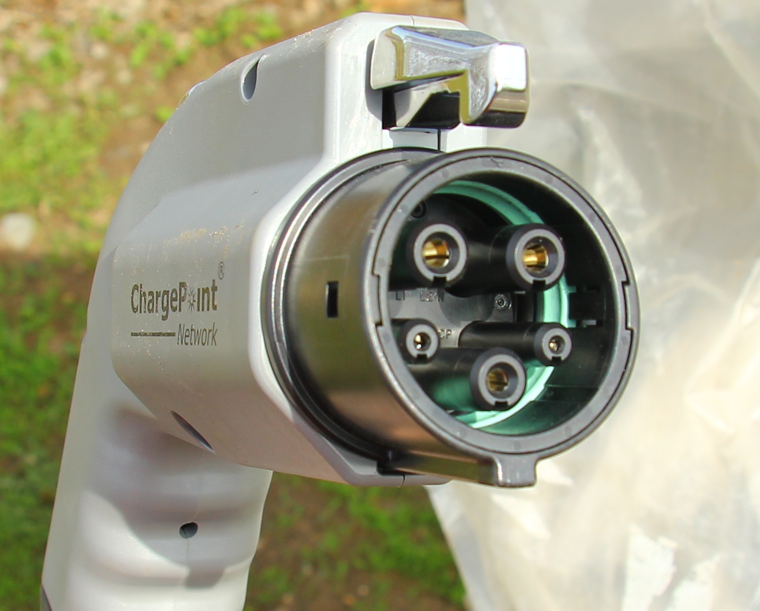
 | |||
| Pinouts for SAE J1772, looking at end of plug (attached to EVSE cord) | |||
| L1 | Line 1 | single-phase AC | |
| L2/N | Line 2 / Neutral | single-phase AC | |
| CP | Control pilot | post-insertion signalling | |
| PP | Proximity pilot | pre-insertion signalling | |
| PE | Protective earth | full-current protective earthing system | |
| CCS Combo 1 extension adds two extra high-current DC pins underneath, and the two Alternating Current (AC) pins for Neutral and Line 1 are not populated. | |||
SAE J1772, also known as a J plug or Type 1 connector after its international standard, IEC 62196 Type 1, is a North American standard for electrical connectors for electric vehicles. It is maintained by SAE International under the formal title "SAE Surface Vehicle Recommended Practice J1772, SAE Electric Vehicle Conductive Charge Coupler".[1]
The SAE maintains the general physical, electrical, communication protocol, and performance requirements for the electric vehicle conductive charge system and coupler. The intent is to define a common electric vehicle conductive charging system architecture including operational requirements and the functional and dimensional requirements for the vehicle inlet and mating connector.
The J1772 5-pin standard supports a wide range of single-phase (1φ) alternating current (AC) charging rates. They range from portable devices that can connect to a household NEMA 5-15 outlet that can deliver 1.44 kW (12 A @ 120 V) to hardwired equipment that can deliver up to 19.2 kW (80 A @ 240 V).[2] These connectors are sometimes informally referred to as chargers, but they are "electric vehicle supply equipment" (EVSE), since they only supply AC power to the vehicle's on-board charger, which then converts it to the direct current (DC) needed to recharge the battery.
The Combined Charging System (CCS) Combo 1 connector builds on the standard, adding two additional pins for DC fast charging up to 350 kW.
History
[edit]
The main stimulus for the development of SAE J1772 came from the California Air Resources Board (CARB). Early electric vehicles like the General Motors EV1 and Toyota RAV4 EV used Magne Charge (SAE J1773), an inductive system. CARB rejected the inductive technology in favor of conductive coupling to supply electricity for recharging. In June 2001, CARB adopted the SAE J1772-2001 standard as the charging interface for electric vehicles in California.[3][4] This early version of the connector was made by Avcon and featured a rectangular connector capable of delivering up to 6.6 kW of electrical power.[5][6] The California regulations mandated the usage of SAE J1772-2001 beginning with the 2006 model year.
CARB later asked for higher current delivery than the 6.6 kW that the 2001 J1772 (Avcon) standard supported. This process led to the proposal of a new round connector design by Yazaki which allowed for an increased power delivery of up to 19.2 kW delivered via single phase 120–240 V AC at up to 80 amps. In 2008, CARB published a new standard that mandated the usage of the new connector beginning with the 2010 model year;[7] this was approved in 2012.[8]
The Yazaki plug that was built to the new SAE J1772 plug standard successfully completed certification at UL. The standard specification was subsequently voted upon by the SAE committee in July 2009.[9] On January 14, 2010, the SAE J1772 REV 2009 was adopted by the SAE Motor Vehicle Council.[10] The companies participating in or supporting the revised 2009 standard include smart, Chrysler, GM, Ford, Toyota, Honda, Nissan, Rivian, and Tesla.
The SAE J1772-2009 connector specification was subsequently added to the international IEC 62196-2 standard (“Part 2: Dimensional compatibility and interchangeability requirements for a.c. pin and contact-tube accessories”) with voting on the final specification slated to close in May 2011.[11][needs update] The SAE J1772 connector is considered a “Type 1” implementation providing a single phase coupler.[12]
Vehicle equipment
[edit]The SAE J1772-2009 was adopted by electric vehicle manufacturers in the Chevrolet Volt and the Nissan Leaf. The connector became standard equipment in the U.S. market due to the availability of charging stations supporting it in the nation's electric vehicle network (helped by funding such as the ChargePoint America program drawing grants from the American Recovery and Reinvestment Act).[13][14]
The European versions were equipped with a SAE J1772-2009 inlet as well until the automotive industry settled on the IEC Type 2 “Mennekes” connector as the standard inlet – since all IEC connectors use the same SAE J1772 signaling protocol the car manufacturers are selling cars with either a SAE J1772-2009 inlet or an IEC Type 2 inlet depending on the regional market. There are also (passive) adapters available that can convert J1772-2009 to IEC Type 2 and vice versa. The only difference is that many European versions have an on-board charger that can take advantage of three-phase electric power with higher voltage and current limits even for the same basic electric vehicle model (such as the Chevrolet Volt/Opel Ampera).[citation needed]
Combined Charging System (CCS)
[edit]
In 2011, SAE developed a J1772/CCS Combo Coupler variant of the J1772-2009 connector. This was to support the Combined Charging System standard for direct current (DC) fast charging, which includes the standard 5-pin J1772 connector along with an additional two larger pins to support fast DC charging. Combo 1 accommodates charging at 200–920 volts DC and up to 350 kW.[1][needs update] The combination coupler also uses power-line communication technology to communicate between the vehicle, off-board charger, and smart grid.[15] Seven car makers (Audi, BMW, Daimler, Ford, General Motors, Hyundai, Porsche, Volvo, and Volkswagen) agreed in late 2011 to introduce the Combined Charging System in mid-2012.[16] The first vehicles using the SAE Combo plug were the BMW i3 released in late 2013, and the Chevrolet Spark EV released in 2014.[17]
In Europe, the combo coupler is based on the Type 2 (VDE) AC charging connector (Combo 2) maintaining full compatibility with the SAE specification for DC charging and the HomePlug Green PHY PLC protocol.[18] In 2019 Tesla introduced the Model 3 with a CCS Combo 2 plug in Europe, but has not introduced models with CCS in the US. With the introduction of the Model 3 in Europe, Tesla added CCS charging cables to V2 Superchargers (supporting both CCS Combo 2 and Tesla DC Type 2). European V3 and V4 Tesla Superchargers include only a CCS charging cable.[19]
Properties
[edit]Connector
[edit]The J1772-2009 connector is designed for single phase alternating current electrical systems with 120 V or 240 V such as those used in North America and Japan. The round 43-millimetre (1.7 in) diameter connector is keyed and has five pins (viewed from outside of the plug):[20]
|
|
Row | Position | Function | Notes |
|---|---|---|---|---|
| Top[a] | 1 | L1 | "AC Line 1" | |
| 2 | N | "AC Neutral" for 120 V Level 1 charging or "AC Line 2" for 208–240 V Level 2 charging | ||
| Bottom[b] | 3 | PE | "Protective Earth" aka Ground | |
| Middle[c] | 4 | PP | "Proximity Pilot" aka "plug present", which provides a signal to the vehicle's control system so it can prevent movement while connected to the electric vehicle supply equipment (EVSE; i.e., the charging station), and signals the latch release button to the vehicle.[citation needed] | |
| 5 | CP | "Control Pilot" is a communication line used to negotiate charging level between the car and the EVSE, and it can be manipulated by the vehicle to initiate charging and can carry other information.[21] The signal is a 1 kHz square wave at ±12 volts generated by the EVSE to detect the presence of the vehicle, communicate the maximum allowable charging current, and control charging begin/end.[22] |
- ^ Top row is spaced 6.8 mm (0.27 in) above the centerline of the connector and the pins are spaced 15.7 mm (0.62 in) apart about the centerline.
- ^ Bottom row is spaced 10.6 mm (0.42 in) below the centerline of the connector.
- ^ Middle row is spaced 5.6 mm (0.22 in) below the centerline of the connector and the pins are spaced 21.3 mm (0.84 in) apart about the centerline.
The connector is designed to withstand 10,000 mating cycles (a connection and a disconnection) and exposure to the elements. With 1 mating cycle per day, the connector's lifespan should exceed 27 years.[23]
Release mechanism
[edit]-
 Black release button on an SAE J1772 plug in a mockup car
 -
 SAE J1772 plugs operated by thumb at a VinFast charging station
 -
 Adaptor cable from Nissan with Type 1 plug for the car, Type 2 plug for a European charger socket
 -
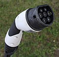 IEC 62196 Type 2 connector with openings on the side for automatic release
.jpg)


The SAE J1772 or Type 1 plug is locked into the car with a hook that is manually operated, mostly by pressing a button with the thumb, which interrupts power. This allows anybody to stop charging and even theft of the cable. To prevent this, the European IEC 62196 Type 2 connector has openings on the side for automatic locking and release, operated by the car owner via remote control. If the car locks or releases its plug, the charger follows suit according to the PP signal.
In addition, the charge port on many modern cars with a J1772 connector have an extendable pin that blocks the J1772 latch from being raised. By extending this pin, it becomes impossible to raise the release latch. In this way, the vehicle can prevent a plugged-in J1772 connector from being removed. This is essential for the CCS implementation where the connector is not designed to break the heavy DC charging current.
Charging
[edit]The SAE J1772-2017 standard defines four levels of charging: AC Level 1, AC Level 2, DC Level 1, and DC Level 2.[24] Earlier released revisions of J1772 also listed a never-implemented AC Level 3, which was considered but never implemented.
| Charge method | Voltage (V) | Phase | Max. current, continuous (A) |
Branch circuit breaker rating (A)[a] |
Max. power (kW) |
|---|---|---|---|---|---|
| AC Level 1 | 120 | 1 | 12 | 15 | 1.44 |
| 16 | 20 | 1.92 | |||
| AC Level 2 | 208 or 240 | 1 | 24–80 | 30–100 | 5.0–19.2 |
| AC Level 3[b] | 208–600 | 3 | 63–160 | 80-200 | 22.7–166 |
| Charge method | Voltage (V) | Phase | Max. current (A) | Max. power (kW) | |
| DC Level 1 | 50–1000 | – | 80 | 80 | |
| DC Level 2 | 50–1000 | – | 400 | 400 | |
- ^ Per NEC article 625.41, branch circuit rating must be at least 125% of EVSE maximum continuous current
- ^ As noted in Appendix M of the SAE J1772 standard document, a third AC charge method was considered but never implemented for light vehicles. For heavy and industrial vehicles, this was left to the SAE J3068 Medium and Heavy Duty Vehicle Conductive Charging Task Force Committee which permits the J1772 protocol at 400 VAC or less and requires a newer LIN protocol above 400 VAC (LIN is recommended at all voltages). J3068 uses the Type 2 (Mennekes connector) possibly supplying up to 166 kW.[25] The J1772 AC Level 3 mode using single phase power would have provided up to 96 kW at a nominal voltage of 240 V AC and a maximum current of 400 A. This power level is closer to what J3068 implemented a decade later at up to 600 VAC, although J3068 version 1 only supports up to 250 amps.
For example, the 2020 Chevrolet Bolt has a 66-kWh lithium-ion battery and a 7.2-kW onboard charging module; with an EPA range of 259 miles (417 km) and energy efficiency of 118 mpg‑e (29 kW⋅h/100 mi; 17.7 kW⋅h/100 km),[26] it can use its portable charge cord to charge at AC Level 1 (120 V, 12 A) to get up to 4 mi (6.4 km) of range per hour or go off an AC Level 2 charging unit (240 V, 32 A) to get up to 25 mi (40 km) of range per hour. Using an optional DC fast charging (DCFC) port, this model can also charge at up to 55 kW to get up to 180 mi (290 km) of range per hour.
Other EVs use an 800 V battery architecture (such as those on Hyundai's E-GMP platform) to charge much faster. According to Hyundai, "With a 350 kW DC charger, IONIQ 5 can charge from 10 percent to 80 percent in just 18 minutes. According to WLTP cycle, IONIQ 5 users only need to charge the vehicle for five minutes to get 100 km of range."[27] These vehicles are capable of accepting up to 230kW until about 50% State of charge, allowing these vehicles to recharge much quicker than similar EVs with lower voltage batteries.
Some EVs extend J1772 to allow AC Level 1 (120 V) charging at greater than 16 amps. This is useful, for example, at RV parks where TT-30 ("Travel Trailer" - 120 V, 30 A) receptacles are common. These allow charging at up to 24 amps. However, this level of 120 V charging has not been codified into J1772.
Another extension, supported by the North American Charging System, is Level 2 charging at 277 V. Like 208 V, 277 V is commonly found in North American commercial three-phase circuits.
Safety
[edit]The J1772 standard includes several levels of shock protection, ensuring the safety of charging even in wet conditions. Physically, the connection pins are isolated on the interior of the connector when mated, ensuring no physical access to those pins. When not mated, J1772 connectors have no power at the pins;[28] they are not energized until commanded by the vehicle.[29]
The proximity detection pin is connected to a switch in the connector release button. Pressing the release button causes the vehicle to stop drawing current. As the connector is removed, the shorter control pilot pin disconnects first, causing the EVSE to drop power to the plug. This also ensures that the power pins do not disconnect under load, causing arcs and shortening their life. The ground pin is longer than the other pins, so it connects first and breaks last.
Signaling
[edit]
The signaling protocol has been designed for the following charging sequence.[29]
- Supply equipment signals presence of AC input power
- Vehicle detects plug via proximity circuit (thus the vehicle can prevent driving away while connected) and can detect when latch is pressed in preparation for plug removal.
- Control Pilot (CP) functions begin
- Supply equipment detects plug-in electric vehicle (PEV)
- Supply equipment indicates to PEV readiness to supply current
- PEV ventilation requirements are determined
- Supply equipment current capacity provided to PEV
- PEV commands energy flow
- PEV and supply equipment continuously monitor continuity of safety ground
- Charge continues as determined by PEV
- Charge may be interrupted by disconnecting the plug from the vehicle
The technical specification was described first in the 2001 version of SAE J1772 and subsequently the IEC 61851-1 and IEC TS 62763:2013. The charging station puts 12 V on the Control Pilot (CP) and the Proximity Pilot (AKA Plug Present: PP) measuring the voltage differences. This protocol does not require integrated circuits like other charging protocols, making the SAE J1772 robust and operable through a temperature range of −40 °C to +85 °C.
Control Pilot
[edit]Control Pilot (Mode): The charging station sends a 1 kHz square wave on the control pilot that is connected back to the protective earth on the vehicle side by means of a resistor and a diode (voltage range ±12.0±0.4 V). The live wires of public charging stations are always dead if the CP–PE (Protective Earth) circuit is open, although the standard allows a charging current as in Mode 1 (maximum 16 A). If the circuit is closed, the charging station can also verify that the protective earth is functional. The vehicle can request a certain charging function by setting the resistance between the CP and PE pins; 2.7 kΩ announces a Mode 3 compatible vehicle (vehicle detected) which does not require charging. 880 Ω says the vehicle is ready to charge, and 240 Ω requests with ventilation charging, in which case the charging stations supplies charging power only if the area is ventilated (i.e., outdoors).
The Control Pilot line circuitry examples in SAE J1772:2001 show that the current loop CP–PE is connected permanently on the vehicle side via a 2.74 kΩ resistor, making for a voltage drop from +12 V to +9 V when a cable is hooked up to the charging station, which activates the wave generator. The charging is activated by the vehicle by adding parallel 1.3 kΩ resistor resulting in a voltage drop to +6 V or by adding a parallel 270 Ω resistor for a required ventilation resulting in a voltage drop to +3 V. Hence the charging station can react by only checking the voltage range present on the CP–PE loop.[30] Note that the diode only makes for a voltage drop in the positive range. Any negative voltage on the CP–PE loop is blocked by D1 in the vehicle, any significant current that does flow in the CP–PE loop during the negative period shuts off the current as being considered a fatal error (like touching the pins).
For IEC62196-2 male plugs the Control Pilot pin is shorter to prevent untethered cables being used as extension leads, This prevents connecting downstream cables that may have a lower current capability a cable of a higher current rating.
| Base status | Charging status | Resistance, CP–PE | Resistance, R2 | Voltage, CP–PE |
|---|---|---|---|---|
| Status A | Standby | Open, or ∞ Ω | +12 V | |
| Status B | Vehicle detected | 2740 Ω | +9±1 V | |
| Status C | Ready (charging) | 882 Ω | 1300 Ω | +6±1 V |
| Status D | With ventilation | 246 Ω | 270 Ω | +3±1 V |
| Status E | No power (shut off) | 0 V | ||
| Status F | Error | -12 V |
Control Pilot (Current limit): The charging station can use the wave signal to describe the maximum current that is available via the charging station with the help of pulse-width modulation. A 16% PWM is a 10 A maximum, a 25% PWM is a 16 A maximum, a 50% PWM is a 32 A maximum and a 90% PWM flags a fast charge option.[31]
The PWM duty cycle of the 1 kHz CP signal indicates the maximum allowed mains current. According to the SAE it includes socket outlet, cable and vehicle inlet. In the US, the definition of the ampacity (ampere capacity, or current capacity) is split for continuous and short term operation.[31] The SAE defines the ampacity value derived by a formula based on the 1 ms full cycle (of the 1 kHz signal) with the maximum continuous ampere rating being 0.6 A per 10 μs up to 850 μs (with the lowest (100 μs/10 μs) × 0.6 A = 6 A). Above 850 μs, the formula requires subtraction of 640 μs and multiplying the difference by 2.5. For example ((960 μs − 640 μs)/10 μs) × 2.5 A = 80 A.[30]
| PWM | SAE continuous | SAE short term |
|---|---|---|
| 50% | 30 A | 36 A peak |
| 40% | 24 A | 30 A peak |
| 30% | 18 A | 22 A peak |
| 25% | 15 A | 20 A peak |
| 16% | 9.6 A | |
| 10% | 6 A |
Proximity Pilot
[edit]The proximity pin, PP (also known as plug present), as shown in the SAE J1772 example pinout, describes the switch, S3, as being mechanically linked to the connector latch release actuator. During charging, the EVSE side connects the PP–PE loop via S3 and a 150 Ω R6; when opening the release actuator a 330 Ω R7 is added in the PP–PE loop on the EVSE side which gives a voltage shift on the line to allow the electric vehicle to initiate a controlled shut off prior to actual disconnection of the charge power pins. However, many low-power adapter cables do not offer that locking actuator state detection on the PP pin.
Under IEC 62196 the Proximity Pin is also used to indicate the cable capacity – this is relevant for non-tethered EVSEs.
The resistor is coded to the maximum current capability of the cable assembly. The EV interrupts the current supply if the current capability of the cable is exceeded as detected by the measurement of the Rc (shown as R6 in the J1772 signaling circuit above), as defined by the values for the recommended interpretation range.
Rc is placed between the PP and PE, within the detachable cable assembly.
| Current capability of the cable assembly | Rc (±3%) | Recommended interpretation range by the EVSE |
|---|---|---|
| 13 A | 1.5 kΩ / 0.5 W | 1–2.7 kΩ |
| 20 A | 680 Ω / 0.5 W | 330 Ω – 1 kΩ |
| 32 A | 220 Ω / 1 W | 150–330 Ω |
| 70 A single-phase / 63 A three-phase | 100 Ω / 1 W | 50–150 Ω |
P1901 powerline communication
[edit]In an updated standard due in 2012, SAE proposes to use power line communication, specifically IEEE 1901, between the vehicle, off-board charging station, and the smart grid, without requiring an additional pin; SAE and the IEEE Standards Association are sharing their draft standards related to the smart grid and vehicle electrification.[33]
P1901 communication is compatible with other 802.x standards via the IEEE 1905 standard, allowing arbitrary IP-based communications with the vehicle, meter or distributor, and the building where chargers are located. P1905 includes wireless communications. In at least one implementation, communication between the off-board DC EVSE and PEV occurs on the pilot wire of the SAE J1772 connector via HomePlug Green PHY power line communication (PLC).[34][35][36]
Competing standards
[edit]A competing proposal known as the Mennekes connector initiated by RWE and Daimler was standardized in 2011's IEC 62196 as its Type 2 connector. It has been widely adopted as the European Union's standard single- and three-phase coupler.[12][37] The connector adopted the same protocols for the pilot pin as J1772's J-Plug. The IEC specification allows for up to 63 A and 43.6 kW. In 2018, the SAE J3068 committee released an enhancement to the EU connector tailored for the North American industrial market allowing up to 160 A / 166 kW on 3φ power.
The same IEC 62196-2 standard also specified a pair of Type 3 connector from Scame Global providing a single- and three-phase coupler with shutters.[12] After a 2016 approval by the IEC for a small modification to the Mennekes connector optionally allowing shutters, Type 3 has been deprecated.
Tokyo Electric Power Company has developed a specification solely for automotive high-voltage DC fast charging using the JARI DC connector and formed the CHAdeMO (charge de move, equivalent to "charge for moving") association with Japanese automakers Mitsubishi, Nissan and Subaru to promote it.[38]
See also
[edit]- SAE J3068 — Electric Vehicle Power Transfer System Using a Three-Phase Capable Coupler
- North American Charging System
References
[edit]- ^ SAE International (2017-10-13). "SAE Electric Vehicle and Plug in Hybrid Electric Vehicle Conductive Charge Coupler J1772_201710" (DOC). SAE Standards. SAE International. Retrieved 2022-11-14.
- ^ "Basics of SAE J1772". Open EVSE. Retrieved 2022-07-13.
- ^ "Rulemaking: 2001-06-26 Updated and Informative Digest ZEV Infrastructure and Standardization" (PDF). title 13, California Code of Regulations. California Air Resources Board. 2002-05-13. Archived (PDF) from the original on 2010-06-15. Retrieved 2010-05-23.
Standardization of Charging Systems
- ^ "ARB Amends ZEV Rule: Standardizes Chargers & Addresses Automaker Mergers" (Press release). California Air Resources Board. 2001-06-28. Archived from the original on 2010-06-16. Retrieved 2010-05-23.
the ARB approved the staff proposal to select the conductive charging system used by Ford, Honda and several other manufacturers
- ^ California Air Resources Board; Alexa Malik. "Rulemaking: 2001-06-28 15 DAY NOTICE ZEV Infra 15day Ntc2-28.doc" (PDF). California Air Resources Board. Archived (PDF) from the original on 2009-06-13. Retrieved 2009-10-23.
- ^ "SAE J1772-2001(older AVCON) Electric Vehicle Chargers". CarStations. 2013-01-24. Archived from the original on 2014-02-03. Retrieved 2014-01-25.
- ^ "Report on the Current Situation and Future Direction of Electric Vehicle Charger Standardisation" Archived 2021-08-03 at the Wayback Machine, SMMT, July 2010
- ^ "Attachment B-5. Final Regulation Order, Zero Emission Vehicle Regulation: Electric Vehicle Charging Requirements, Title 13, California Code of Regulations" (PDF). title 13, California Code of Regulations. California Air Resources Board. 2012-03-22. Archived (PDF) from the original on 2017-02-15. Retrieved 2017-06-21.
Section 1962.3. Electric Vehicle Charging Requirements
- ^ Sam Abuelsamid (2009-06-29). "Underwriters Laboratories approves SAE J1772 charging plug". Archived from the original on 2009-07-01. Retrieved 2009-10-10.
Underwriters Laboratories has completed its certification testing on the connector developed by Yazaki.
- ^ "SAE standard on EV charging connector approved". SAE International. 2010-01-15. Archived from the original on 2010-02-06. Retrieved 2010-03-14.
- ^ "Document: 23H/250/CDV - : IEC 62196-2 Ed. 1: Plugs, socket-outlets, vehicle connectors and vehicle inlets - Conductive charging of electric vehicles - Part 2: Dimensional compatibility and interchangeability requirements for a.c. pin and contact-tube accessories", IEC, 13 December 2010
- ^ a b c “IEC International Standard for EV charging — A step forward for global EV roll-out” Archived 2016-05-20 at the Wayback Machine, IEC Newslog, 3. February 2011
- ^ "Development of the SAE J1772 Standard of Electric Vehicle Charger". AG Electrical Technology Co., Ltd. 2021-05-24. Retrieved 2023-06-08.
- ^ "ChargePoint Announces the Successful Completion of its ARRA-Funded ChargePoint America Program". ChargePoint, Inc. 2013-06-11. Retrieved 2023-06-08.
- ^ "New SAE International Quick-Charge EV Connector Standard Gaining Momentum" (Press release). SAE International. 2011-08-04. Archived from the original on 2011-09-26. Retrieved 2011-08-11.
- ^ "Universal charging for electric cars". Auto123.com. 2011-11-15. Archived from the original on 2011-12-28. Retrieved 2011-12-17.
- ^ Seabaugh, Christian (2013-09-13). "First Test: 2014 Chevrolet Spark EV 2LT SparkSS". Motor Trend. Archived from the original on 2015-09-16. Retrieved 18 February 2014.
- ^ Dr. Heiko Doerr (2011-11-08). "Current Status of the Combined Charging System" (PDF). Coordination Office Charging Interface (Audi, VW, BMW, Daimler, Porsche). Archived from the original (PDF) on 2012-04-26.
- ^ "Supercharger Support". tesla.com. Retrieved 2025-04-08.
- ^ Miles, Dennis (July 2010). "A Brief Outline of J1772 Operation and Configuration" (PDF). evdl.org. Archived (PDF) from the original on 5 August 2021. Retrieved 5 August 2021.
- ^ Pratt, Rick (2014). "Vehicle Communications and Charging Control" (PDF). Pacific Northwest National Laboratory. p. 7. Archived (PDF) from the original on 15 September 2021. Retrieved 5 August 2021.
- ^ "SAE EV Charging Systems Committee, SAE Electric Vehicle Conductive Charge Coupler". Archived from the original on 2012-05-24. Retrieved 2009-10-23.
- ^ 10,000 / 365 = 27.4
- ^ "SAE Electric Vehicle and Plug in Hybrid Electric Vehicle Conductive Charge Coupler". SAE International. 2017-10-13. Archived from the original on 2020-01-02. Retrieved 2019-01-01.
- ^ McLaughlin, Jim (23 October 2017). SAE J3068TM 3-phase AC charging update (PDF). EPRI Truck and Bus meeting (Report). Archived (PDF) from the original on 15 December 2017. Retrieved 13 December 2017.
J3068 adopts the European Type 2 coupler, 5 wire with neutral and adds a simple, robust, inexpensive and established datalink: LIN pulse width is the same as 5% PWM, so filters do not change.
- ^ U.S. Environmental Protection Agency and U.S. Department of Energy. "Compare Side-by-Side - 2020 Chevrolet Bolt EV". fueleconomy.gov. Archived from the original on 2020-03-23. Retrieved 2019-01-01.
- ^ "IONIQ 5 Charging | Eco - Hyundai Worldwide". HYUNDAI MOTORS. Retrieved 2023-12-01.
- ^ "Charging the Chevy Volt web chat". GM-Volt.com. 2009-08-20. Archived from the original on 2010-11-27. Retrieved 2010-09-03.
When a J1772 standard plug (like on the Volt) is disconnected from the vehicle, no voltage is present at the pins.
- ^ a b Gery Kissel, SAE J1772 Task Force Lead (2010-02-18). "SAE J1772 Update For IEEE Standard 1809 Guide for Electric-Sourced Transportation Infrastructure Meeting" (PDF). SAE International. Archived from the original (PDF) on 2011-03-04. Retrieved 2010-09-03.
{{cite web}}: CS1 maint: numeric names: authors list (link) - ^ a b "SAE J1772 - SAE Electric Vehicle Conductive Charger Coupler". August 2001. Appendix A, Typical Pilot Line Circuitry. Archived from the original on 2012-05-24. Retrieved 2012-04-09.
- ^ a b c Anro Mathoy (17 January 2008). "Definition and implementation of a global EV charging infrastructure". BRUSA Elektronik. Retrieved 2012-04-08.
- ^ TABLE 4-7: RESISTOR CODING FOR PLUGS (IEC 61851-22, ANNEX B)
- ^ Pokrzywa, Jack; Reidy, Mary (2011-08-12). "SAE's J1772 'combo connector' for ac and dc charging advances with IEEE's help". SAE International. Archived from the original on 2012-06-14. Retrieved 2011-08-12.
- ^ Harper, Jason D. (2013). "Development and Implementation of SAE DC Charging Digital Communication for Plug-in Electric Vehicle DC Charging". SAE Technical Paper Series. Vol. 1. Papers.sae.org. doi:10.4271/2013-01-1188. Archived from the original on 2014-02-01. Retrieved 2014-01-25.
- ^ "Smartgrid EV Communication module (SpEC) SAE DC Charging Digital Communication Controller - Energy Innovation Portal". Techportal.eere.energy.gov. Archived from the original on 2014-01-23. Retrieved 2014-01-25.
- ^ "Smart Grid EV Communication Module | Argonne National Laboratory". Anl.gov. Archived from the original on 2014-02-19. Retrieved 2014-01-25.
- ^ Winfried Tröster (2009-01-29). "62196 Part 2-X: Dimensional interchangeability requirements for pin and contact-tube vehicle couplers" (PDF). International Electrotechnical Commission. Archived from the original (PDF) on 2011-07-16. Retrieved 2010-04-15.
- ^ "Tokyo Electric Power Licenses Aker Wade to Build Level III Fast Chargers". Green Car Congress. 2010-01-15. Archived from the original on 2010-01-22. Retrieved 2010-04-13.
External links
[edit]| Vehicle |   | ||||||||||
|---|---|---|---|---|---|---|---|---|---|---|---|
| Source | |||||||||||
| Charging |
| ||||||||||
| Practices | |||||||||||