Hubbry Logo
Leaky feederLeaky feederMain
Open search
Leaky feeder
Community hub
Leaky feeder
logo
8 pages, 0 posts
0 subscribers
Be the first to start a discussion here.
Leaky feeder
Leaky feeder
from Wikipedia
Diagram of leaky feeder cable

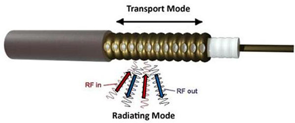
A leaky feeder is a kind of antenna used for communication in mines, tunnels, and other enclosed spaces.[1] The commercial name radiating cable[2][3][better source needed][4] emphasizes that it is designed to radiate, unlike most cables.

Principle

[edit]

A leaky feeder communication system consists of a cable run along tunnels which emits and receives radio waves, functioning as an extended antenna. The cable is "leaky" in that it has gaps or slots in its outer conductor to allow the radio signal to leak into or out of the cable along its entire length. Because of this leakage, line amplifiers are inserted at regular intervals, typically every 350 to 500 metres, to boost the signal. The signal is usually picked up by portable transceivers carried by personnel. Transmissions from the transceivers are picked up by the feeder and carried to other parts of the tunnel, allowing two-way radio communication throughout the tunnel system.

The system has a limited range and because of the frequency it uses (typically VHF or UHF), transmissions cannot pass through solid rock, which limits the system to a line-of-sight application. It does, however, allow two-way mobile communication.

Due to the signal loss, a leaky feeder is usually used for frequencies under 1 GHz. Above that frequency, the losses require too many repeaters, thus making other options more effective. Antennae (omni, panel or bi-directional) or even distributed antenna systems are more often used for higher frequency bands.

Applications

[edit]

Mining

[edit]

Leaky feeders are used in the mining industry for wireless communication between miners. The system is used as a primary communication system with a transceiver small enough to be comfortably worn for an entire shift.[5]

Underground railways

[edit]

The leaky feeder system is used for underground mobile communication in mass transit railways. In Delhi, Hong Kong, and Copenhagen, leaky feeders were installed during construction.[citation needed][clarification needed] This gives emergency services seamless mobile communication from underground to the surface.

The London Underground uses a leaky feeder system for its internal communication network Connect.[6] However, the communication used by the emergency services, Airwave, was not compatible and did not work below ground. The fact that this situation continued to exist after the 1987 King's Cross fire was criticised in the reports from the 7 July 2005 London bombings, where it hampered rescue efforts.[7] In March 2020, two additional leaky feeder cables were brought online in the Jubilee line extension tunnels between Canning Town and Westminster. One of these cables provided commercial 4G coverage for passengers, both in the tunnels and on station platforms,[8] whilst the second cable provided coverage for the Home Office's Emergency Services Network (ESN),[9] which is currently being rolled out to replace the ageing Airwave network.[10] This trial section is the first to be brought online as part of a project to provide both commercial 4G coverage and ESN coverage across the entire Tube network.

Tyne and Wear Metro was the first railway in the UK to use leaky feeder cables for public mobile phone connectivity, in its city-centre underground tunnels. Initially this was a 2G signal, but then mobile operator EE upgraded this to 4G for their customers. As of 2023, operator Nexus are planning a comprehensive upgrade to mobile data coverage, including in the tunnels.[11]

An alternative to using leaky feeder in underground railways is to use Distributed Antenna System (DAS). A DAS system was deployed in some New York City Subway stations by Transit Wireless to provide Wi‑Fi and mobile phone and data coverage for customers.[12]

In-flight wireless networks

[edit]

Leaky feeder antenna systems can also be used to allow use of onboard mobile phones and Wi‑Fi on passenger aircraft.[13][14] The weight and space requirements of leaky feeder systems are usually lower than comparable antenna systems, thus saving space and fuel. The even field strengths produced by runs of leaky feeders spanning the entire fuselage improve coverage while requiring less transmitting power.

Industrial buildings

[edit]

Leaky feeders are used in hotels, warehouses and other industrial buildings where it is difficult to get Wi‑Fi coverage using normal access points. Some installations have 50–75 meters of leaky wire connected to the antenna output of each access point.[15]

RFID

[edit]

A leaky feeder modified with metallic strips can be used as a radio-frequency identification (RFID) antenna.[16][17]

See also

[edit]

References

[edit]
[edit]
Revisions and contributorsEdit on WikipediaRead on Wikipedia
from Grokipedia
A leaky feeder is a specialized engineered with periodic slots or apertures in its outer conductor to intentionally radiate and receive signals along its entire length, functioning as a distributed antenna for bidirectional communication in environments where conventional is obstructed, such as underground mines, tunnels, and . This design allows portable radios within proximity—typically tens of meters—to couple with the cable, enabling voice, data, and transmission over distances spanning kilometers when augmented by inline amplifiers to counteract signal . Developed in the as a hybrid wired-wireless solution to overcome line-of-sight limitations in subterranean settings, leaky feeder systems originated in operations to facilitate reliable contact between workers and surface control, addressing hazards like cave-ins and gas pockets through enhanced coordination. Their deployment expanded to metropolitan rail systems and industrial tunnels, where they provide uniform coverage absent dead zones inherent in point-to-multipoint antennas. Key characteristics include low-loss inner conductors for efficient signal carriage and controlled leakage rates calibrated to frequency bands like VHF or UHF, ensuring minimal external interference while maximizing internal . Systems often integrate with leaky feeder amplifiers spaced at intervals to boost signals, supporting standards-compliant operations for emergency response and routine monitoring. Despite advancements in alternatives like fiber-optic distributed antenna systems, leaky feeders remain valued for their simplicity, cost-effectiveness, and robustness in harsh, conductive environments.

History

Invention and Patenting

The leaky feeder principle, involving the intentional radiation of radio frequency signals from a to enable communications in enclosed environments such as tunnels, was first systematically described and experimentally validated in by N. Monk and H.S. Winbigler. In their work, published in the IRE Transactions on Vehicular Communications, they demonstrated two-way VHF communication with moving trains inside the North River tunnel using an open-wire or cable laid parallel to the tracks, which allowed signal leakage to couple with the tunnel's conductive walls for propagation. This approach addressed the limitations of direct in long, shielded spaces by treating the tunnel as part of an artificial , with the leaky line compensating for through controlled field leakage. While the disclosure established the foundational concept without a specific , practical implementations evolved toward designs for improved shielding and efficiency. In the early , as applications expanded to and underground facilities, George Brownell, an American , developed a leaky featuring periodic slots or apertures in the outer conductor to facilitate uniform signal . Brownell filed a for this "leaky " on October 29, 1971, which was granted as U.S. No. 3,945,006 on September 21, 1976, describing a structure optimized for leakage while minimizing external interference. This marked a key advancement in commercial viability, enabling rugged, low-loss cables suitable for harsh environments, though earlier non- leaky lines had already seen limited deployment. Subsequent patents built on these foundations, such as those for integrated amplifiers and slot geometries, but Brownell's work is credited with pioneering the modern leaky feeder form factor widely adopted in the 1970s for communications. Historical reviews confirm that pre-1970s systems relied more on simpler configurations, with variants proliferating after protections facilitated manufacturing scalability.

Initial Deployments and Evolution

The initial deployments of leaky feeder systems occurred in underground coal mines in the during the late 1960s, driven by the need for reliable radio communication in wet and confined environments where traditional wiring failed. The began evaluating leaky transmission lines in 1967 as a superior alternative to twin feeders, with early trials conducted at the Longannet colliery to extend VHF signal coverage along roadways. These systems utilized cables with intentional apertures in the outer conductor to radiate signals uniformly, enabling two-way voice communication between mobile radios and fixed base stations over distances previously unattainable without excessive infrastructure. By the , leaky feeder technology had proliferated to North American underground mines, where it addressed similar challenges in extending radio range for and operational coordination. Early installations typically employed analog VHF frequencies, with line-powered amplifiers spaced every 300-500 meters to offset and maintain signal strength up to several kilometers. This era marked the shift from rudimentary open-braided cables—first conceptualized in —to engineered radiating cables optimized for mine environments, incorporating periodic boosters for consistent coverage. Evolution in the subsequent decades involved enhancements for broader applications and improved performance. In underground railways, leaky feeders were adapted for train traffic control, with systems like those in metros providing bidirectional communication by the . Technical refinements included better shielding materials to minimize interference and support higher frequencies, enabling integration with telemetry for monitoring equipment and personnel tracking. By the , deployments expanded beyond to tunnels and urban subways, while hybrid digital-analog variants emerged to handle voice, low-bandwidth , and eventually compatibility with optic backhauls, though initial costs—often exceeding $800,000 for comprehensive mine setups—limited adoption to high-risk sites. Recent advancements focus on capabilities for autonomous vehicles, yet core principles of controlled leakage persist from early mine trials.

Technical Principles

Core Mechanism of Signal Leakage

A leaky feeder cable functions as a specialized transmission line designed to intentionally radiate (RF) signals along its length, unlike standard cables that confine electromagnetic waves within the inner conductor, , and outer . The core mechanism relies on periodic apertures, such as slots or perforations, introduced into the outer conductor, which disrupt the shielding and permit controlled leakage of the guided TEM (transverse electromagnetic) mode into the surrounding environment. Signal begins with an RF transmitter injecting into the cable, where it travels as a mode wave supported by currents on the inner and outer conductors separated by the insulator. At each in the outer conductor—typically longitudinal slots spaced at intervals matching the —the discontinuity causes a portion of the electric and magnetic fields to couple externally, converting part of the guided into radiated waves or evanescent fields that extend radially from the cable. This leakage manifests as an intentional of the forward-propagating signal, typically engineered to values between 3 and 15 dB per 100 meters depending on and design, ensuring uniform coverage without excessive loss over long runs. The external coupling to mobile transceivers occurs primarily through two mechanisms: direct radiation for farther distances, where slots act as distributed slot antennas emitting omnidirectional or directional fields, and near-field for close-range devices, where diffracted leakage fields from the mode interact with the mobile antenna within a "congestion radius" of approximately 3-5 meters. This dual-mode behavior—radiation-dominated at higher frequencies and at lower—arises from the physics of mode conversion at the slots, where the outer conductor's incomplete shielding reduces lateral , allowing electromagnetic energy to penetrate the environment while maintaining primary along the cable axis. Inline amplifiers, spaced every 300-500 meters, counteract cumulative leakage losses to sustain signal strength.

Design Features and Materials

Leaky feeder cables are transmission lines engineered with deliberate imperfections in the outer conductor to enable controlled electromagnetic signal leakage along their length, providing coverage in enclosed environments such as tunnels and mines. The primary design feature is the incorporation of slots, apertures, or loose braiding in the shielding, which allows a portion of the guided wave energy to radiate externally as a leakage field, typically achieving losses of around 60 dB at distances of 6 meters from the cable at 450 MHz. These imperfections contrast with standard cables, where the outer conductor is designed to minimize leakage; in leaky feeders, the slots are often arranged in a periodic or continuous pattern, such as a single continuous slot or zig-zag configurations, to balance and radiation efficiency across frequencies up to 2.5 GHz. Common diameters include 1/2 inch (13 mm) and 7/8 inch (22 mm) for underground applications, with standardized at 50 ohms to match typical radio equipment. Materials selection prioritizes low loss, flexibility, and environmental durability, particularly flame retardancy for use. The inner conductor is typically solid or bare -covered aluminum for reduced , surrounded by a gas-injected to achieve propagation velocities of 85-88%. The outer conductor employs a bonded aluminum or tape with integrated slots or a braided wire configuration featuring intentional gaps, enabling the surface transfer impedance necessary for leakage while maintaining structural integrity. The outermost jacket is usually (PVC) or flame-retardant (FRPE), often low-smoke zero-halogen (LSZH) formulations compliant with standards like MSHA for underground safety, with operating temperatures ranging from -40°C to +85°C. These materials ensure the cable's remains manageable, such as 2.22 dB per 100 feet at 450 MHz for mid-sized variants, supporting long runs with periodic amplification.

Propagation Characteristics

Leaky feeder cables propagate signals as guided transverse electromagnetic (TEM) waves along the coaxial transmission line, with controlled leakage through periodic slots or apertures in the outer conductor enabling radiation to proximate receivers. This dual function results in higher longitudinal than sealed coaxial cables, as energy is intentionally dissipated for coverage, balanced by design parameters optimizing transmission over distances of 1-2 km per segment. velocity is determined by the dielectric constant of the insulating material, while the phase constant maintains coherence along the cable, supporting applications in VHF to UHF bands from approximately 30 MHz to 1 GHz. The longitudinal attenuation constant, representing signal loss per unit length, increases with due to greater radiative at shorter wavelengths and is influenced by conductor size, losses, and environmental interactions such as proximity to walls or accumulation. For a typical 1-5/8 inch RF feeder leaky cable, values are as follows:
Frequency (MHz) (dB/100 m)
750.60
1500.90
3001.30
4501.60
9002.70
These losses necessitate inline amplifiers spaced according to total , with exacerbated in braided or bifilar designs sensitive to . loss, the power transfer inefficiency between the cable's and an external antenna, is a critical metric typically specified at 2 m for 50% or 95% probability, ranging from 60-90 dB overall but varying inversely with antenna proximity and orientation. Frequency dependence shows initial increases followed by decreases in some slot-based designs, as slot dimensions resonate better with higher frequencies; for the same 1-5/8 inch cable:
Frequency (MHz)Coupling Loss 50% (dB)Coupling Loss 95% (dB)
756372
1506676
3006872
4506770
9005860
Short-term fluctuations up to 20 dB occur due to multipath in confined spaces, with overall system loss equaling longitudinal plus coupling loss. Above frequencies (e.g., 130 MHz), cables operate in radiating mode for uniform field distribution, though mounting position can add 15 dB/100 m effective loss at higher bands like 1800 MHz.

System Components

Cable Construction


Leaky feeder cables consist of a structure modified to enable intentional (RF) signal radiation along their length. The core components include a central conductor, a insulator, an outer conductor with engineered apertures, and an external protective jacket. This design allows most of the signal to propagate internally while a controlled portion leaks outward to provide distributed coverage.
The inner conductor is typically a solid or stranded annealed wire or bare -clad aluminum (BCCAI) tube, selected for high conductivity and mechanical strength to minimize transmission losses. Surrounding this is a low-loss , often gas-injected foamed , which supports the —usually 50 ohms—and reduces while maintaining flexibility. The outer conductor, critical for leakage, differs from standard cables by incorporating slots, gaps, or perforations rather than a continuous . Common implementations include a bonded aluminum tape or foil with a continuous single slot, periodic non-uniformly spaced slots, or zig-zag apertures, which control loss and —often directing emission over approximately 180 degrees with slots positioned on one side. In flexible variants, a loosely woven serves as the outer conductor to permit RF escape, while rigid types may use corrugated with intentional discontinuities. These features balance shielding against external interference with uniform signal leakage, typically achieving losses around 60 dB at frequencies like 2.4 GHz. An outer jacket, usually (PE), (PVC), or low-smoke zero-halogen (LSZH) materials, encases the assembly for environmental protection, flame retardancy, and mechanical durability in harsh settings like mines. Specialized jackets may include dual layers for water blocking in direct-buried applications or enhanced UV and cold resistance. Cable diameters vary, such as 0.350 inches for smaller flexible models, enabling installation around curves without kinking. Manufacturing emphasizes precision in slot geometry and spacing to ensure consistent —e.g., 1.34 dB per 100 feet at 150 MHz for larger sizes—and broadband operation from VHF to 2.5 GHz.

Amplifiers and Accessories

In leaky feeder systems, bidirectional amplifiers (BDAs) are essential components that compensate for the longitudinal signal loss in radiating cables, typically spaced every 300 to 500 meters depending on cable and frequency band. These amplifiers boost both transmit and receive signals to ensure uniform coverage over extended distances, with models like the PBE BDA-4 providing up to 20 dB gain in VHF bands while operating on a wide supply voltage range of 6 to 24 VDC for flexible underground deployment. VHF BDAs, such as those from Becker Mining Systems, are designed specifically to counter cable losses in environments, supporting voice and communications by amplifying signals bidirectionally without introducing significant or distortion. UHF and LTE-compatible BDAs extend functionality to broadband applications, with devices like the MB-UBDA-01-WW operating in the 435-455 MHz uplink band to integrate voice and services in a single unit. Line amplifiers, such as the Digital Drift DDLFS-LA-V75, incorporate features like Ethernet monitoring for remote diagnostics, passing with minimal loss while providing selectable gain levels for VHF signals at 75 impedance. These amplifiers must comply with safety standards, as evidenced by MSHA approval for the PBE BDA-4 in 2014, ensuring reliability in hazardous locations by preventing signal degradation through rock, equipment, and cable leakage. Accessories complement amplifiers by facilitating connections, termination, and power distribution. Coupling units or taps connect portable radios to the cable, injecting or extracting signals at access points with minimal , often using 75 impedance to avoid reflections. Line splices join cable segments, such as the Sigma Communication Systems VHF splice, which maintains 75 integrity with low loss for seamless extension. Terminators at cable ends prevent standing waves by absorbing residual signals, while power inserters supply DC voltage to amplifiers along the line, typically via the cable's center conductor. Backup power systems, including DC UPS units with remote monitoring, ensure continuous operation during outages by charging batteries and delivering 30 VDC to the network. Connectors and adapters, customized for corrugated designs, secure joints against environmental stresses like and in tunnels.

Integration with Transmitters and Receivers

Leaky feeder systems integrate with transmitters by connecting the proximal end of the cable to the output port of a or transmitter via connectors, such as N-type or BNC, to inject radiofrequency (RF) signals into the cable for and leakage along its length. This setup treats the cable as an extended antenna, with signal typically managed at 5-10 dB per 100 meters depending on and cable design, necessitating inline amplifiers spaced every 300-500 meters to maintain output power levels up to 50 watts. Receiver integration occurs similarly, with the cable's signal output coupled to the receiver input, enabling the capture of RF signals leaked into the cable from portable within proximity (usually 10-50 meters radially). In two-way systems, a single bidirectional cable connects to a or at the to separate transmit and receive paths, preventing interference while supporting frequencies in VHF (30-300 MHz) or UHF (300-3000 MHz) bands common in applications. Impedance matching, typically at 50 or 75 ohms, is critical during integration to minimize reflections and standing waves, achieved through matching transformers or stubs if the transmitter/receiver impedance differs from the cable's . Portable radios interface wirelessly with the cable via electromagnetic , relaying signals to the base receiver without direct wired connection, as demonstrated in underground evaluations where received signal strength indicators (RSSI) remain viable up to 2-3 km along the cable with proper amplification. Systems often incorporate in receivers to handle varying leakage levels, ensuring consistent performance in environments with multipath interference.

Applications

Mining and Underground Extraction

Leaky feeder systems provide essential communication in underground operations, where rock formations and geometries severely attenuate conventional signals. These systems employ a intentionally designed with apertures or slots to radiate and receive radio frequencies along its length, enabling uniform coverage over distances exceeding several kilometers when amplified. In contexts, the cable is typically suspended from roofs, connecting portable radios used by workers to a surface for voice dispatch, emergency alerts, and coordination. Deployment began in the as a hybrid wired- solution to overcome challenges in confined subterranean spaces. Regulatory mandates have solidified their role in safety protocols, particularly following the U.S. Mine Improvement and New Emergency Response (MINER) Act of 2006, enacted after disasters like and Darby where communication failures hindered evacuations. The Act requires wireless two-way communication and electronic tracking systems capable of functioning post-accident, with leaky feeders approved by the (MSHA) for compliance, such as VHF models like the MCA 1000 with MSHA approval 23-A090003-0 supporting minimum RFI distances of 8 feet. Systems must maintain integrity during emergencies, including separation from blasting operations up to 50 feet as permitted in emergency response plans. Beyond voice, leaky feeders facilitate data transport for mine monitoring, such as integrating Internet Protocol over land mobile radio for sensor networks tracking ventilation, gas levels, and equipment status. In coal mines, VHF leaky feeders predominate due to their penetration in dusty, methane-prone environments, often interfacing with tracking tags for personnel location. Empirical assessments indicate reliable performance in active workings, though susceptibility to cable damage from roof falls or machinery necessitates redundant segments and regular testing. Adoption extends to metal and hard-rock mines globally, enhancing productivity by enabling remote control of machinery and real-time fault reporting.

Tunneling and Underground Rail Systems

Leaky feeder systems provide essential radio coverage in tunneling projects, where and walls severely attenuate signals and conventional antennas cannot maintain consistent over extended distances. These systems utilize radiating cables installed along lengths to enable voice, data, and emergency communications for workers and equipment. According to evaluations by the U.S. Centers for Disease Control and Prevention, leaky feeders are deployed in tunnels too long for standard antennas, supporting land mobile radio services in such confined environments. In underground rail systems like subways and metros, leaky feeders facilitate bidirectional communication for train control, passenger mobile connectivity, and public safety networks, addressing challenges posed by curved tunnels, station platforms, and signal blockage from metal structures. For example, in the London Underground, two dedicated leaky feeder cables were installed by early 2020—one for commercial mobile services and a second for the U.K. Home Office's emergency services network—to deliver in-tunnel coverage across multiple lines. Technical assessments in metro tunnels have compared broadband and radiating-mode leaky feeders, measuring coupling losses as low as 50-70 dB under dry conditions to optimize signal leakage for VHF/UHF frequencies. International standards, such as those from the , endorse leaky feeders for land mobile applications in tunnels, recommending designs that handle moisture and mounting difficulties while ensuring uniform rates of 5-10 dB per 100 meters. In and metro expansions, secure cable clamping prevents sagging and maintains , critical for minimizing reflections in linear topologies exceeding several kilometers. These deployments often integrate with TETRA or LTE protocols, providing scalable solutions that outperform distributed antenna systems in cost and reliability for deep underground rail corridors.

Industrial Facilities and Large Structures

Leaky feeder systems provide essential coverage in industrial facilities where conventional antennas struggle due to signal from metal machinery, walls, and expansive layouts. In factories and refineries, these systems connect sensors, cameras, and control equipment across large sites, enabling transmission for operational monitoring and protocols. This application is particularly valuable in hazardous areas, such as flammable gas plants, where intrinsically safe communication prevents ignition risks from traditional devices. In chemical plants and refineries, leaky feeders support communications for worker coordination and emergency response, radiating signals uniformly along cable runs installed parallel to production lines or corridors. These installations mitigate multipath and shadowing effects common in environments with dense metallic , ensuring consistent coverage without the need for numerous discrete antennas. Systems often integrate with existing networks for remote control of valves, pumps, and alarms, as documented in evaluations of radiating cable performance in complex industrial settings. Warehouses and other large enclosed structures utilize leaky feeders for paging, dispatching, and systems, where high shelving and stacked goods create dead zones. Cables are typically suspended from ceiling joists or routed along structural beams to deliver contoured indoor RF distribution, as per manufacturer guidelines for such deployments. In buildings and sprawling industrial complexes, they extend coverage to underground or semi-enclosed service areas, supporting voice and over distances exceeding several kilometers when amplified. International standards recognize their efficacy in large buildings with inadequate natural , emphasizing self-contained setups for reliable in-building networks.

Military and Security Environments

Leaky feeder systems provide essential radio coverage in underground facilities, such as bunkers and tunnels, where line-of-sight propagation is obstructed by reinforced structures and earth, ensuring bi-directional VHF and UHF communications for operations. In these environments, the cable's intentional signal leakage along its length maintains uniform coverage without dead zones, penetrating obstacles like walls that attenuate conventional antennas. This reliability supports , data, and links in confined spaces, reducing risks during emergencies or sustained operations. In security applications, leaky feeders enable perimeter and monitoring by extending radio networks along linear installations, such as fences or routes, where or foliage disrupts standard signals. Their design offers resistance to electronic jamming and interference, minimizing detectability through a reduced RF signature compared to point-source antennas, which is critical for stealthy operations in electronic warfare scenarios. Systems like those integrated with radio technologies further enhance adaptability, allowing low-latency reconfiguration in dynamic threats. For field deployments and urban combat, leaky feeders facilitate communications in complex terrains, including or building interiors repurposed for defense, by combining wired backbone stability with mobility. This setup has been adapted for military use since at least the early , with advancements in software-defined radios improving integration with existing defense networks. Overall, these systems prioritize operational continuity in high-stakes environments over broader-area coverage, outperforming alternatives in signal consistency through physical infrastructure.

Specialized Uses

In correctional facilities, leaky feeder systems provide controlled communication to mitigate risks from unauthorized signals. These systems leverage near-field signal to limit coverage to specific zones, enabling selective access for staff or monitored inmate devices while preventing external interference or organized crime coordination. A 2014 of mobile systems in socially sensitive environments highlights how leaky feeders' intentional signal leakage supports such applications without compromising containment. Commercial implementations, such as those integrated with systems, further adapt leaky feeders for vandal-prone areas, distributing RF signals along cable runs to cover cell blocks or common areas with minimal . In , leaky feeder antennas enable in-flight wireless connectivity for passenger devices. These specialized cables, designed for interiors, support by uniformly distributing signals across cabins where traditional antennas face multipath challenges from metallic structures. developed such antennas operating from 400 MHz to 6 GHz, facilitating seamless integration with onboard systems for voice, data, and as of 2013. Connectors tailored for applications ensure durability under vibration and pressure changes, with Type N variants supporting high-frequency operations in confined airborne spaces. Leaky feeders also serve niche indoor environments like airport terminals and multi-level parking garages, where RF signals attenuate due to and . Deployments in these structures use the cable's slotted design to create linear coverage along corridors or ramps, supporting public safety radios or paging without extensive antenna arrays. Technical literature notes their use in such commercial complexes for consistent signal strength over extended runs, dating back to adaptations for non-underground linear paths.

Advantages

Reliability in Challenging Environments

Leaky feeder systems excel in environments characterized by high RF , multipath , and physical obstructions, such as underground mines and tunnels, where conventional antennas fail to maintain consistent coverage. These systems propagate signals along the cable length, minimizing dead zones and enabling bidirectional communication over distances up to 1-2 km per segment with appropriate amplification. In channels typical of confined spaces, leaky feeders demonstrate lower bit error rates (BER) compared to single-antenna setups at equivalent signal-to-noise ratios, supporting modulation schemes like QPSK and M-QAM for reliable data transmission. ![Leaky feeder cable deployment][float-right] Empirical assessments confirm stable received power levels, ranging from -15 to -25 dBm over 50 m in tunnel tests, versus the more variable -5 to -50 dBm from point-source antennas, reducing outage risks in dynamic settings like expanding mine workings. Coupling loss between 60-90 dB, adjustable via cable design and mounting, ensures predictable signal leakage despite environmental factors like moisture or proximity to conductive surfaces, with bifilar cables offering lower loss (as low as 30 dB) in optimal underground conditions. Systems incorporate repeaters to extend range and mitigate longitudinal attenuation, maintaining integrity amid interference from machinery or geological shifts, thus supporting critical applications like vehicle-to-infrastructure (V2I) links in tunnels. Durability is enhanced by the cable's rugged , tolerant of harsh exposures including , dust, and ingress, allowing scalable deployment that adapts to evolving without frequent signal degradation. Optimal slot spacing, such as 20 mm at 3 GHz frequencies, further optimizes by minimizing BER and enabling gigabit-per-second rates with reduced RF power needs, lowering interference in dense, enclosed areas. While sensitive to installation specifics, proper empirical site tuning—accounting for multipath variations up to 20 dB—yields high uptime, positioning leaky feeders as a primary solution for safety-critical voice and data in non-line-of-sight scenarios.

Coverage Uniformity and Scalability

Leaky feeder systems deliver uniform coverage by radiating radio signals continuously along the cable length, resulting in consistent signal strength proximate to the cable with variations typically below 5 dB in tested environments. This contrasts with discrete antenna deployments, which exhibit greater signal fluctuations and dead zones in confined spaces like tunnels or indoor areas. The design ensures reliable within 3-10 meters radially from the cable, minimizing nulls and supporting portable radios without line-of-sight dependencies. Scalability is achieved through modular extension via inline amplifiers or , spaced every 350-500 meters to offset and maintain over extended runs. Unamplified segments cover 300-450 meters, but amplified configurations enable deployments spanning tens of kilometers, such as over 40 km in long tunnels with multiple boosters. This approach facilitates incremental expansion in dynamic settings like expanding mines, integrating with base stations and fiber backhauls for larger networks without compromising uniformity.

Empirical Performance Metrics

Leaky feeder systems are characterized by longitudinal , which measures signal loss along the , typically ranging from 2 to 4 dB per 100 meters in VHF frequencies depending on cable construction and environmental factors such as mounting proximity to walls or contamination. Coupling loss, representing the power loss between the feeder and a mobile antenna, commonly falls between 60 and 90 dB, with short-distance variations up to 20 dB following a in tunnel or mine environments; design values of at least 90 dB are recommended for system stability to account for these fluctuations. These metrics apply across frequencies from 3 MHz to 1,000 MHz, with lower VHF bands preferred for economic viability despite higher frequencies offering better in tunnels but increased sensitivity to external influences. Field tests demonstrate achievable coverage distances of 1 to 2 km per segment with , though practical limits in mines often require amplifiers every 300 to 500 meters to maintain reliable voice or data links. In evaluations at 60 MHz, attenuation rates varied from 0.6 to 1.1 dB per 100 feet (approximately 2 to 3.6 dB per 100 meters), with coupling losses of 71 to 83 dB measured at 20 feet from the cable. Environmental moisture, such as rain or snow, can degrade sensitivity by 10 to 15 dB on average, with profile variations up to 22 dB, though slight ground moisture may enhance by 1 to 2 dB; these effects underscore the need for weather-resistant designs in outdoor or damp underground applications.
ParameterTypical ValueFrequency/ContextNotes/Source
Longitudinal Attenuation2–4 dB/100 mVHF (30–300 MHz)Varies with cable type and mounting
Coupling Loss (50%)50–60 dB or higherGeneral leaky cablesExceeded by 50% of measurement points
Coverage per Segment1–2 km with 3 MHz–1 GHzAchievable in tests; shorter in practice
Moisture Impact10–15 dB sensitivity reduction60 MHz, coaxial testsAverage; up to 22 dB variation
Higher-frequency applications, such as V2X communications up to 6 GHz, show increased in the 0.1–0.2 GHz range, leading to reduced reception power, though empirical automotive tests confirm viable longitudinal coverage when integrated into structures like barriers. These metrics highlight leaky feeders' suitability for uniform signal distribution in confined spaces, albeit with trade-offs in bandwidth-limited scenarios compared to point-source antennas.

Limitations and Criticisms

Technical Drawbacks

Leaky feeder systems exhibit signal along the cable length, where radiated power decreases progressively due to intentional leakage, necessitating inline amplifiers every 300–500 meters to maintain coverage, which introduces additional noise and complexity. This attenuation limits effective range without amplification, particularly in long tunnels exceeding several kilometers. Bandwidth capacity remains constrained, typically supporting narrow frequency bands such as 900 MHz or dual bands like 900/1800 MHz, rendering them inadequate for high-data-rate applications including Wi-Fi or cellular services above 1 GHz, where signal losses intensify. Systems lack meaningful support for multiple-input multiple-output (MIMO) configurations due to absent polarization and spatial diversity, resulting in reduced throughput and elevated latency compared to discrete antenna deployments. The cables' physical vulnerability to mechanical damage, such as cuts from equipment or structural shifts in tunnels, compromises system integrity, as disruptions at any point along the linear path can sever coverage for downstream sections. Troubleshooting faults proves challenging owing to the distributed nature of the infrastructure, with no granular visibility into specific failure loci without extensive . Susceptibility to electromagnetic interference arises from adjacent cables or environmental factors, demanding precise spacing and shielding to mitigate , while in enclosed spaces can alter radiation patterns unpredictably. Overall throughput limitations further restrict utility in bandwidth-intensive scenarios, confining applications primarily to voice and low-data protocols rather than data transfer.

Cost and Installation Challenges

Leaky feeder systems entail significant upfront costs, driven by the specialized cables designed for signal leakage and supporting hardware including amplifiers, couplers, and power supplies. These expenses often exceed those of alternative technologies; for instance, deploying leaky feeders for 500 meters of coverage can cost approximately three times more than comparable systems, factoring in materials and labor under standard European rates. Installation poses substantial challenges in confined underground environments such as tunnels and mines, where precise cable routing and mounting are essential to maintain . Cables must be loosely strapped to structural meshing or supports, avoiding bundling with other lines, and typically require hangers spaced every 50 cm, necessitating hydraulic lifts and skilled labor that extends deployment time by a factor of three compared to discrete antenna setups. Physical vulnerabilities compound these difficulties, as the cables are susceptible to damage from explosions, roof falls, and elevated temperatures, potentially disrupting coverage beyond the impact site and requiring UHF amplifiers at intervals of about 300 meters to compensate for . Maintenance further escalates long-term costs, with fault isolation demanding extensive manual inspections along the entire length, often leading to operational and full shutdowns for repairs.

Comparisons with Alternative Technologies

Leaky feeders provide linear, continuous (RF) coverage along their length, making them suitable for elongated underground paths such as tunnels and mine corridors, but they differ from distributed antenna systems (DAS) in deployment and performance. DAS typically employs discrete antennas spaced throughout an area to distribute signals from a central source, enabling support for multiple frequencies and operators simultaneously, whereas leaky feeders function as a passive radiating optimized for single-frequency voice communications in VHF or UHF bands. Active DAS variants amplify signals at remote points, offering higher capacity for data-intensive applications like cellular, which leaky feeders struggle with due to increased at frequencies above 1 GHz. In comparison to mesh networks, commonly used in underground for tracking and transmission, leaky feeders excel in providing uniform coverage without reliance on node-to-node relaying but lag in scalability and robustness for high-throughput needs. systems, operating on self-healing topologies, support precise tracking and integration with sensors, outperforming leaky feeders in accuracy and expandability for dynamic mine layouts, as evidenced by deployments where reduced compared to cable-based alternatives. Leaky feeders require physical cable runs susceptible to damage from activities, whereas networks adapt via hops, though they demand more power and can suffer interference in metallic environments. Antenna-based solutions, such as helical antennas deployed in underground settings, offer superior performance for high-bandwidth protocols like or cellular over leaky feeders, particularly in terms of signal reach and data rates. Tests in environments show helical antennas achieving higher throughput and lower at 2.4 GHz and 5 GHz bands, where leaky feeders exhibit rapid signal degradation beyond 100-200 meters without amplifiers. Economically, helical setups reduce installation costs by avoiding extensive cabling and minimize maintenance, as they eliminate the need for inline or couplers prone to failure in harsh conditions. Repeaters and bi-directional amplifiers (BDAs) serve as point-specific signal boosters, contrasting with the distributed leakage of leaky feeders, and are often integrated into leaky systems for range extension but function independently in open-area coverage. BDAs amplify incoming signals without the continuous path dependency of cables, providing flexibility for non-linear spaces, though they require line-of-sight or precise placement to avoid multipath issues, unlike the inherent path-following nature of leaky feeders. In mine evaluations, leaky feeders with integrated repeaters maintain voice reliability over kilometers but underperform standalone repeaters in adaptability to reconfiguration without rewiring.

Recent Developments

Advancements in Bandwidth and Integration

Modern leaky feeder systems have seen enhancements in bandwidth through the adoption of materials and designs supporting higher frequencies and multi-band operations, enabling simultaneous transmission of voice, data, and video services. These cables can achieve extremely high bandwidths across several radio bands, facilitating applications like real-time monitoring in confined spaces where traditional signals degrade. For example, optimizations at 5 GHz frequencies have extended coverage in underground settings while maintaining usable signal strength over extended distances, though with trade-offs in peak intensity compared to line-of-sight antennas. Integration with digital protocols has transformed leaky feeders from analog voice conduits into versatile backbones for IP-based networks, leveraging existing cabling for Ethernet-compatible data transport without full infrastructure overhauls. in 2019 validated IP packet routing over leaky feeders using standard modems, achieving reliable VoIP and data rates in tunnels by modulating signals onto the radiating cable. By 2025, vendors like RACOM have deployed hybrid solutions pairing leaky feeders with serial-to-IP radios (e.g., RipEX2 units) for high-speed and RTU communications underground, bridging legacy RF with modern packet-switched systems. Further advancements include adaptations for -like throughput and low-latency demands in automation-heavy environments, such as autonomous in mines, where leaky feeders now support the bandwidth for and remote control signals. In August 2025, DARK-5G's leaky feeder implementation demonstrated consistent signal propagation around bends and obstacles, outperforming discrete antennas in signal uniformity for underground trials. ' tunnel-specific system, launched in 2025, boosts overall efficiency by 20% via reduced interference and enhanced coupling, integrating seamlessly with fiber backhauls for scalable bandwidth upgrades. Emerging hybrids combine leaky feeders with mesh networks and IoT gateways, enabling and AI-driven analytics over unified infrastructures.

Market Growth and Case Studies

The global leaky feeder cables market, valued at approximately $500 million in 2025, is projected to expand at a compound annual growth rate (CAGR) of 7% through 2033, driven by increasing demand for reliable communications in underground mining, tunneling, and infrastructure projects where traditional wireless signals fail due to signal attenuation. This growth reflects heightened regulatory emphasis on safety in confined environments, with adoption rising in sectors requiring real-time voice, data, and IoT integration for monitoring equipment and personnel. Key trends include advancements in high-bandwidth variants supporting Wi-Fi and hybrid systems, alongside eco-friendly cable designs, contributing to a forecasted market size exceeding $800 million by the early 2030s. In underground coal mining operations, leaky feeder systems have demonstrated empirical reliability for extending radio coverage along haulage tunnels and ore loading areas, as assessed in U.S. facilities where they maintained consistent signal strength over extended cable runs without significant degradation from environmental factors like dust or moisture. A U.S. Centers for Disease Control and Prevention (CDC) evaluation of deployed systems in active mines confirmed their utility for voice dispatch and emergency signaling, with performance metrics showing low rates under load, though requiring periodic amplification for optimal coverage beyond 1-2 km. Case studies from networks, such as those integrating leaky feeders with radio-over-fiber extensions, highlight in European sites where surface-based units extended signals deep into subsurface RTUs, enabling automated monitoring and reducing by facilitating proactive fault detection. In scenarios, low-cost leaky feeder deployments have provided alternatives to permanent , supporting VHF/UHF for team coordination during post-incident recovery, with field tests indicating signal leakage uniformity superior to ad-hoc in linear topologies. These implementations underscore the technology's causal advantages in non-line-of-sight environments, though economic viability depends on site-specific cable lengths and integration costs.

References

Add your contribution
Related Hubs
User Avatar
No comments yet.