Hubbry Logo
Pre-chargePre-chargeMain
Open search
Pre-charge
Community hub
Pre-charge
logo
8 pages, 0 posts
0 subscribers
Be the first to start a discussion here.
Pre-charge
Pre-charge
from Wikipedia
Peak inrush current into a high voltage capacitor upon power up can stress the component, reducing its reliability.

Pre-charge of the powerline voltages in a high voltage DC application is a preliminary mode which limits the inrush current during the power up procedure.

A high-voltage system with a large capacitive load can be exposed to high electric current during initial turn-on. This current, if not limited, can cause considerable stress or damage to the system components. In some applications, the occasion to activate the system is a rare occurrence, such as in commercial utility power distribution. In other systems such as vehicle applications, pre-charge will occur with each use of the system, multiple times per day. Precharging is implemented to increase the lifespan of electronic components and increase reliability of the high voltage system.

Background: inrush currents into capacitors

[edit]

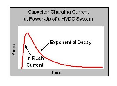
Inrush currents into capacitive components are a key concern in power-up stress to components. When DC input power is applied to a capacitive load, the step response of the voltage input will cause the input capacitor to charge. The capacitor charging starts with an inrush current and ends with an exponential decay down to the steady state condition. When the magnitude of the inrush peak is very large compared to the maximum rating of the components, then component stress is to be expected. The current into a capacitor is known to be : the peak inrush current will depend upon the capacitance C and the rate of change of the voltage (dV/dT). The inrush current will increase as the capacitance value increases, and the inrush current will increase as the voltage of the power source increases. This second parameter is of primary concern in high voltage power distribution systems. By their nature, high voltage power sources will deliver high voltage into the distribution system. Capacitive loads will then be subject to high inrush currents upon power-up. The stress to the components must be understood and minimized.

The objective of a pre-charge function is to limit the magnitude of the inrush current into capacitive loads during power-up. This may take several seconds depending on the system. In general, higher voltage systems benefit from longer pre-charge times during power-up.

Peak Inrush Current Into Powerline Capacitors Increases with Power-up dV/dT
11,000 μF Powerline Capacitor Peak Inrush Current at Power-Up of a 15 A Feed
1 ms 10 ms 100 ms 1 s
v = 28 V 310 A 31 A 3.1 A 0.31 A
v = 610 V 6710 A 671A 67A 7A
Color Key:
___ = High risk of tripping the breaker
___ = Careful selection of breaker with suitable rating required to avoid tripping
___ = Good

Consider an example where a high voltage source powers up a typical electronics control unit which has an internal power supply with 11000 μF input capacitance. When powered from a 28 V source, the inrush current into the electronics unit would approach 31 amperes in 10 milliseconds. If that same circuit is activated by a 610 V source, then the inrush current would approach 670 A in 10 milliseconds. It is wise not to allow unlimited inrush currents from high voltage power distribution system activation into capacitive loads: instead the inrush current should be controlled to avoid power-up stress to components.

Definition of a pre-charge function

[edit]
Precharging a high voltage DC power distribution line can control the inrush current into capacitive components, reducing stress and supporting a long component life.

The functional requirement of the high voltage pre-charge circuit is to minimize the peak current out from the power source by slowing down the dV/dT of the input power voltage such that a new "pre-charge mode" is created. The inductive loads on the distribution system must be switched off during the pre-charge mode, due to the dI/dT dependency. While pre-charging, the system voltage will rise slowly and controllably with power-up current never exceeding the maximum allowed value. As the circuit voltage approaches near steady state, then the pre-charge function is complete. Normal operation of a pre-charge circuit is to terminate pre-charge mode when the circuit voltage is 90% or 95% of the operating voltage. Upon completion of pre-charging, the pre-charge resistance is switched out of the power supply circuit and returns to a low impedance power source for normal mode. The high voltage loads are then powered up sequentially.

The simplest inrush-current limiting system, used in many consumer electronics devices, is a NTC resistor. When cold, its high resistance allows a small current to pre-charge the reservoir capacitor. After it warms up, its low resistance more efficiently passes the working current.

Many active power factor correction systems also include soft start.

If the example circuit from before is used with a pre-charge circuit which limits the dV/dT to less than 600 volts per second, then the inrush current will be reduced from 670 amperes to 7 amperes. This is a "kinder and gentler" way to activate a high voltage DC power distribution system.

Benefits of pre-charging

[edit]

The primary benefit of avoiding component stress during power-up is to realize a long system operating life due to reliable and long lasting components.

There are additional benefits: pre-charging reduces the electrical hazards which may occur when the system integrity is compromised due to hardware damage or failure. Activating the high voltage DC system into a short circuit or a ground fault or into unsuspecting personnel and their equipment can have undesired effects. Arc flash will be minimized if a pre-charge function slows down the activation time of a high voltage power-up. A slow pre-charge will also reduce the voltage into a faulty circuit which builds up while the system diagnostics come on-line. This allows a diagnostic shut down before the fault is fully realized in worst case proportions.

In cases where unlimited inrush current is large enough to trip the source circuit breaker, a slow precharge may even be required to avoid the nuisance trip.

Pre-charging is commonly used in battery electric vehicle applications. The current to the motor is regulated by a controller that employs large capacitors in its input circuit.[1] Such systems typically have contactors (a high-current relay) to disable the system during inactive periods and to act as an emergency disconnect should the motor current regulator fail in an active state. Without pre-charge the high voltage across the contactors and inrush current can cause a brief arc which will cause pitting of the contacts. Pre-charging the controller input capacitors (typically to 90 to 95 percent of applied battery voltage) eliminates the pitting problem. The current to maintain the charge is so low that some systems apply the pre-charge at all times other than when charging batteries, while more complex systems apply pre-charge as part of the starting sequence and will defer main contactor closure until the pre-charge voltage level is detected as sufficiently high.

Applications in high voltage power systems

[edit]

References

[edit]
Revisions and contributorsEdit on WikipediaRead on Wikipedia
from Grokipedia
Pre-charge is a fundamental technique in used to mitigate inrush currents in (DC) systems by gradually charging capacitive elements, such as DC-link capacitors, prior to connecting the full power source. This process prevents sudden voltage spikes that could damage components like contactors, fuses, and wiring. In high-voltage applications exceeding 100 V, such as electric vehicles (EVs), hybrid vehicles, inverters, and industrial power supplies, pre-charge circuits typically employ a series and auxiliary switches or contactors to control the charging rate. The circuit operates in stages: initially, with main contactors open, a pre-charge path—often including a resistor—closes to slowly build voltage across the capacitors until it approaches the source level, typically within a threshold like 30 V drop. Once stabilized, the pre-charge path disengages, and the main high-voltage contactors close for normal operation, ensuring no significant inrush occurs. The primary benefits of pre-charge include enhanced system reliability, prolonged component lifespan, and prevention of hazards like arcing or in contactors due to excessive currents. By limiting peak currents to levels, it reduces stress on semiconductors and electromechanical parts, enabling higher power density and safer operation in demanding environments like EV battery systems and DC-DC converters. Without pre-charge, the sudden required to charge large capacitances upon power-up could exceed component ratings, leading to failures or safety risks.

Fundamentals of Pre-charging

Inrush Currents in Capacitors

Inrush current is the maximum instantaneous current drawn by a at the moment it begins charging from a , arising primarily from the capacitor's inherently low (ESR), which offers minimal opposition to the flow of charge. This phenomenon occurs because an uncharged initially presents as a to the applied voltage, allowing charge to accumulate rapidly on its plates until the capacitor voltage approaches the source voltage. In , capacitors with ESR values often below 1 Ω exacerbate the issue, as the total path resistance remains low without intentional limiting elements. The peak inrush current can be derived from the standard RC circuit charging model. For a series RC circuit connected to a DC voltage VV, the current as a function of time is given by I(t)=VRet/(RC),I(t) = \frac{V}{R} e^{-t / (RC)}, where RR is the total resistance in the charging path (including ESR and any external series resistance), CC is the capacitance, and tt is time. At t=0t = 0, the exponential term equals 1, yielding the peak current Ipeak=V/RI_\text{peak} = V / R. This formula highlights how IpeakI_\text{peak} scales inversely with RR; low-ESR capacitors, common in modern designs for efficiency, can thus produce currents orders of magnitude higher than steady-state operating levels. These surges pose several risks to electrical systems. High IpeakI_\text{peak} values can induce voltage dips across the power supply, destabilizing the source and affecting connected devices. They frequently exceed the inrush ratings of fuses or circuit breakers, leading to premature blowing or tripping. Components such as switches, wiring, and semiconductors experience excessive and mechanical stress, accelerating wear or causing outright . Moreover, the abrupt di/dtdi/dt (rate of current change) generates (), which can couple into nearby circuits and degrade . Early observations of inrush currents emerged in 20th-century , with initial documented challenges appearing in circuits around the 1920s as electrolytic capacitors were integrated into radio power supplies for filtering. These wet electrolytic designs, pioneered by figures like Samuel Ruben, relied on high-ESR electrolytes that partially mitigated surges but highlighted the need for current management in low-impedance paths. A representative example illustrates the scale: for a 400 V DC bus capacitor bank of 1000 µF with an ESR of 0.1 Ω, the unconstrained IpeakI_\text{peak} reaches 400/0.1=4000400 / 0.1 = 4000 A, far exceeding typical fuse ratings and risking system damage. Pre-charging techniques address this by gradually building capacitor voltage to limit such peaks.

Purpose and Definition of Pre-charging

Pre-charging refers to the controlled process of gradually applying voltage to a capacitive load, such as DC-link capacitors in , prior to fully connecting it to the main power source, thereby restricting the peak that would otherwise occur due to the capacitor's initial uncharged state. This technique employs a limiting element, typically a in series with a switch, to moderate the charging rate and prevent excessive stress on system components like contactors, fuses, and power supplies. The primary purpose of pre-charging is to safely energize capacitors to their steady-state voltage while maintaining current levels well below the unrestricted inrush, which can exceed hundreds of amperes in high-voltage systems. By doing so, it mitigates risks of arcing, component damage, and system faults during power-up, particularly in applications involving large capacitances where abrupt connection could draw surge currents orders of magnitude higher than steady-state operation. The charging process adheres to the RC time constant principle, defined as τ=R×C\tau = R \times C, where RR is the limiting resistance and CC is the capacitance; this controlled resistance extends the time constant to ensure gradual voltage buildup without overwhelming the source. Pre-charging is distinct from soft-start mechanisms, which focus on overall power supply ramp-up to regulate output voltage in converters, whereas pre-charging specifically targets the initial energization of input or link capacitors. Pre-charging is typically deemed complete when the voltage reaches 90-95% of the supply voltage, at which point the limiting element is bypassed to enable full system operation, often verified through voltage sensing across the . This threshold ensures the remaining voltage differential is minimal, avoiding residual inrush upon main closure while optimizing startup time.

Mechanisms and Implementation

Basic Pre-charge Circuits

Basic pre-charge circuits primarily utilize passive and semi-active components to mitigate inrush currents by gradually charging capacitive loads in power systems. These designs are simple, cost-effective, and widely adopted in applications requiring reliable startup without sophisticated control. A fundamental method involves inserting a series resistor into the power path to limit the initial surge, forming an RC circuit where the resistor dissipates energy and controls the charging rate. In passive resistor-based pre-charge, a fixed , typically rated between 10 and 100 Ω, is placed in series with the load during the initial energization phase. This restricts the peak to a manageable level, preventing arcing at switches or damage to downstream components. The total energy dissipated in the is E=12CV2E = \frac{1}{2} C V^2, where CC is the and VV is the supply voltage; resistor selection must account for this pulse energy to ensure thermal rating is not exceeded, often requiring resistors rated for short-term overloads of several watts based on the system's voltage and duration. Relay or contactor switching enhances this passive approach by automating the 's insertion and removal. A dedicated pre-charge closes first, routing current through the to slowly charge the bank, while the main remains open. Once the voltage approaches the supply level—typically after 100 ms to 1 s—the pre-charge opens, and the main closes to bypass the for efficient steady-state operation. This timing balances quick system readiness with safe current limiting, often determined by the . Diode-based elements are integrated into these circuits to safeguard against transient effects during switching. Freewheeling diodes, connected in parallel with coils, provide a path for inductive kickback current, preventing voltage spikes that could cause or component failure when the relay de-energizes. These diodes ensure smooth transitions without reverse current flow disrupting the pre-charge process. Sizing the pre-charge resistor follows guidelines that prioritize parameters for and . The resistance is selected to keep the maximum ImaxI_{\max} below 10 A, calculated as Imax=VRI_{\max} = \frac{V}{R} for the initial uncharged state, considering the supply voltage and total of the . For instance, in a 400 V with 1000 μF , a 50 Ω yields an initial current under 8 A, with the pre-charge duration around 50 ms. A representative example of such a circuit is the NTC thermistor-based , which serves as a self-regulating alternative. The NTC starts with high resistance (e.g., 50–100 Ω at ) to cap , then decreases to under 1 Ω as it heats from the charging current, automatically bypassing itself without additional switching. This method is passive, compact, and effective for repetitive startups in power supplies up to 480 VAC. These basic circuits help ensure compliance with relevant standards such as IEC 60950-1 for equipment by limiting inrush currents to safe levels, preventing hazardous energy release or overloads.

Advanced Pre-charge Techniques

Advanced pre-charge techniques employ active switching elements such as MOSFETs or IGBTs to enable precise control over charging currents, often through (PWM) to precisely control the average charging current. This approach allows for gradual voltage buildup across capacitors while minimizing stress on components, contrasting with passive methods suitable only for simpler, low-power scenarios. In high-voltage systems, such as those in electric vehicles, these switches are driven by isolated gate drivers to handle voltages up to 800 V, ensuring safe operation during the pre-charge phase before main contactors engage. Modern implementations increasingly use wide-bandgap devices like SiC MOSFETs for reduced losses in high-voltage applications exceeding 800 V, as of 2025. Integration of DC-DC converters, particularly buck or boost topologies, further enhances efficiency by applying stepped voltage increments to the capacitor bank, achieving high efficiencies (often >90%) with minimal dissipation, compared to 50% in traditional resistive pre-charging where half the energy is dissipated as . For instance, a buck converter-based active pre-charge circuit uses a power and to limit average currents to around 4-5 A while charging millifarad-level s to 800 V in under 500 ms, with near-lossless operation due to inductive rather than resistive dissipation. Boost configurations are similarly employed in low-voltage source scenarios to step up to the required DC-link voltage, leveraging existing bidirectional converters in automotive systems for seamless integration. Voltage feedback loops are integral to these techniques, utilizing comparators or microcontrollers to continuously monitor voltage and adjust switching until it approximates the supply voltage, preventing overcharge or insufficient buildup. comparators, for example, sense shunt voltages to maintain current within bounds (e.g., 0.5-8 A peaks), closing the loop via gate drivers for stable operation at switching frequencies up to 47 kHz. Microcontroller-based implementations add flexibility, incorporating Hall sensors or shunts for real-time adjustments in complex setups. Soft-start integrated circuits (ICs) like the LM3488 provide built-in mechanisms to ramp up output voltage gradually, limiting inrush currents during startup in boost or SEPIC pre-charge converters. The LM3488's internal soft-start circuit enforces a 4 ms delay, progressively increasing the duty cycle to control the voltage slew rate and protect downstream components, making it ideal for wide-input (2.97-40 V) applications. In high-power systems exceeding 10 kW, techniques recycle pre-charge energy back to the source via bidirectional DC-DC converters, such as phase-shifted full-bridge topologies, reducing overall losses in repeated cycling scenarios like powertrains. These methods leverage existing onboard chargers to reverse energy flow, minimizing in setups where traditional pre-charging would waste significant power. The evolution of pre-charge techniques reflects broader advances in power semiconductors, shifting from passive resistive methods to active switching approaches, driven by improvements in and IGBT efficiency and control integration.

Benefits and Limitations

Key Advantages

Pre-charging significantly reduces stress on electrical components such as fuses, switches, and s by limiting peak inrush currents to safe levels, thereby extending their operational lifespan and preventing premature failures. In high-voltage systems, uncontrolled inrush can exceed hundreds of amperes, leading to contactor welding, fuse degradation, and overheating, but pre-charge circuits mitigate these issues by gradually building voltage across the load. For example, in automotive DC-link designs, pre-charging limits average current to 5.33 A with peaks at 9.46 A for an 800 V, 1000 µF , compared to instantaneous peaks that could otherwise reach thousands of amperes. Pre-charging enhances power quality by minimizing voltage sags and (). High inrush currents from uncharged capacitors can cause grid voltage dips and generate through rapid current changes, disrupting sensitive equipment, but controlled pre-charging stabilizes the supply and reduces these disturbances. Additionally, advanced pre-charge methods, such as those using topologies, improve energy efficiency by recovering 80-90% of the charging energy through inductive storage rather than dissipating it as heat in resistors, with average power losses dropping from 400 W in resistive designs at 400 V to near-lossless operation in active circuits. The technique also delivers cost savings in large-scale industrial systems by averting component failures and associated , where unplanned outages can thousands of dollars per hour depending on the operation's scale. Solid-state pre-charge solutions further reduce maintenance expenses through higher reliability and no mechanical wear, offering a strong via lower bill-of-materials and extended system uptime. Enhanced safety is another key benefit, as pre-charging lowers risks in high-voltage connections by curbing inrush-induced arcing during switch closure, with response times under 3 µs in modern designs outperforming mechanical relays (1-50 ms).

Potential Challenges

Implementing pre-charge circuits introduces additional design complexity due to the need for extra components, such as resistors, relays, or MOSFETs, alongside control logic to manage switching sequences. This added circuitry can increase the overall (BOM) and system cost, as protective elements and safety features contribute to higher material and assembly expenses. Timing considerations pose significant challenges, as improper delays in the pre-charge phase may result in incomplete capacitor charging, leaving residual inrush current when the main power path engages. For instance, in systems with large capacitive loads, delays shorter than the required charging time (typically 150-400 ms for automotive DC-link capacitors) can fail to fully charge the capacitors, potentially stressing downstream components. Mechanical relays, commonly used in these circuits, exhibit response times of 1-50 ms, further complicating precise timing control. Resistive pre-charge methods generate substantial heat by dissipating the charging energy as output, particularly during repeated operations, which necessitates robust strategies in confined or enclosed systems to prevent overheating. This heat buildup can degrade component reliability and requires careful selection of resistors with adequate power ratings and possibly auxiliary cooling. Common failure modes include mechanical wear in relays, which typically endure only around 10^5 switching cycles before reliability diminishes, and avalanche breakdown triggered by high-voltage spikes during transients. These issues can lead to contactor arcing, welding, or outright device failure, underscoring the need for robust component selection rated for the expected electrical stresses. Sizing the pre-charge elements involves trade-offs, where overly conservative values or circuit parameters can extend startup times beyond 5 seconds, thereby reducing system responsiveness and in applications requiring quick power-up. Balancing with acceptable charge duration is critical to avoid either excessive stress or operational delays. To mitigate these challenges, engineers often employ circuit simulation tools, such as LTSpice, to model and optimize pre-charge behavior, ensuring proper timing, thermal profiles, and component ratings without physical prototyping iterations. These simulations help refine designs to balance protection against inrush currents with minimal impact on performance. As of 2025, the adoption of integrated solid-state pre-charge solutions, compliant with standards like ISO 26262 for automotive functional safety, is increasing to further enhance reliability and reduce mechanical dependencies.

Applications

Power Supply Systems

In switch-mode power supplies (SMPS), pre-charging plays a critical role in gradually charging the bulk capacitors positioned after the rectification stage, thereby limiting the inrush current that occurs upon power-up. This process prevents excessive surges that could damage input components, such as fuses, bridge rectifiers, and contactors, while safeguarding the overall input stages of the power supply. By employing resistors or thermistors in series with the capacitors during initial energization, the voltage across the bulk capacitance rises slowly, reducing peak currents and enhancing system reliability in standard AC-DC converters. In (UPS) systems, pre-charging ensures safe transitions from battery to inverter operation by controlling the to the inverter's input capacitors, avoiding sparks, component stress, and potential failures during startup. Typically implemented with relays and current-limiting elements like PTC thermistors, this mechanism allows the capacitors to charge at a controlled rate—often over 2-3 seconds—before closing the main for full operation. For instance, in systems with a 100 V battery and 50,000 μF , pre-charge circuits can handle up to 250 joules of energy while maintaining current limits suitable for reliable performance. Pre-charging addresses inrush currents inherent to capacitive loads in power supplies, providing a smoother startup waveform observable via oscilloscope traces that reveal a gradual voltage ramp-up and reduced ripple compared to unmitigated connections. In high-power applications like server farm power supply units (e.g., 12 V/100 A configurations), such techniques prevent power surges that could propagate failures across multiple units, ensuring stable operation in dense computing environments. The evolution of pre-charging requirements is evident in standards for consumer and enterprise power supplies; for example, ATX specifications for PC power units have mandated inrush current limiting since the early 2000s to protect components, with modern iterations like ATX Version 3.1 (released in 2023) capping peak inrush at 200 A for 230 VAC inputs (100 A for 115 VAC) across multiple AC cycles, consistent with Version 3.0. This has become integral to preventing repetitive cycling damage and ensuring compatibility in desktop and server-grade systems.

High-Voltage and Specialized Equipment

In electric vehicles (EVs), pre-charging the DC-link capacitors is essential to mitigate inrush currents that could damage insulated gate bipolar transistors (IGBTs) in the traction inverter. Typical DC bus systems operate at 400 V with capacitances around 5000 µF, requiring controlled charging before the main contactor closes to limit peak currents and protect components. This process uses resistors or active switches to gradually build voltage, preventing arcing at relay contacts and ensuring safe operation of the power electronics. Many EV systems integrate pre-charge mechanisms with safety features such as pyrotechnic fuses for battery protection during faults. In applications, pre-charging limits inrush currents in solar inverters during startup from photovoltaic arrays, aligning with safety requirements in standards like UL 1741 for grid-tied equipment. These circuits employ soft-start mechanisms to charge the DC-link capacitors without stressing the input bridge rectifier or capacitors, ensuring reliable to . Similarly, inverters use pre-charge devices, such as auxiliary capacitors and switches, to manage the transition from the generator side to , preventing voltage dips and component wear during connection. Industrial high-voltage motor drives and rail systems rely on pre-charge sequences to safely energize the DC bus, typically lasting from milliseconds to several seconds depending on capacitance and resistor values. In motor drives, this sequence protects semiconductors and contactors from excessive currents, allowing gradual voltage ramp-up before full operation. Rail electrification systems, operating at voltages up to 1500 V DC, incorporate similar timed pre-charging to handle large inductive loads and ensure compliance with safety protocols during power-up. In specialized and applications, pre-charging supports high-voltage systems by managing inrush currents in distribution networks and power supplies, enhancing reliability in demanding environments. Future trends point to integration of (SiC) and (GaN) devices in pre-charge circuits, enabling faster switching and efficiencies exceeding 99% in high-voltage systems by 2030. These wide-bandgap semiconductors reduce losses in resistors and switches, supporting compact designs for EVs and renewables while meeting evolving efficiency standards.

References

Add your contribution
Related Hubs
User Avatar
No comments yet.