
Community hub
Recent from talks
Contribute something
Nothing was collected or created yet.
Gray code
View on Wikipedia
| Gray code | ||||
|---|---|---|---|---|
| 4 | 3 | 2 | 1 | |
| 0 | 0 | 0 | 0 | 0 |
| 1 | 0 | 0 | 0 | 1 |
| 2 | 0 | 0 | 1 | 1 |
| 3 | 0 | 0 | 1 | 0 |
| 4 | 0 | 1 | 1 | 0 |
| 5 | 0 | 1 | 1 | 1 |
| 6 | 0 | 1 | 0 | 1 |
| 7 | 0 | 1 | 0 | 0 |
| 8 | 1 | 1 | 0 | 0 |
| 9 | 1 | 1 | 0 | 1 |
| 10 | 1 | 1 | 1 | 1 |
| 11 | 1 | 1 | 1 | 0 |
| 12 | 1 | 0 | 1 | 0 |
| 13 | 1 | 0 | 1 | 1 |
| 14 | 1 | 0 | 0 | 1 |
| 15 | 1 | 0 | 0 | 0 |
The reflected binary code (RBC), also known as reflected binary (RB) or Gray code after Frank Gray, is an ordering of the binary numeral system such that two successive values differ in only one bit (binary digit).
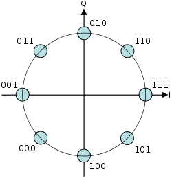
For example, the representation of the decimal value "1" in binary would normally be "001", and "2" would be "010". In Gray code, these values are represented as "001" and "011". That way, incrementing a value from 1 to 2 requires only one bit to change, instead of two.
Gray codes are widely used to prevent spurious output from electromechanical switches and to facilitate error correction in digital communications such as digital terrestrial television and some cable TV systems. The use of Gray code in these devices helps simplify logic operations and reduce errors in practice.[1]
Function
[edit]Many devices indicate position by closing and opening switches. If that device uses natural binary codes, positions 3 and 4 are next to each other but all three bits of the binary representation differ:
| Decimal | Binary |
|---|---|
| ... | ... |
| 3 | 011 |
| 4 | 100 |
| ... | ... |
The problem with natural binary codes is that physical switches are not ideal: it is very unlikely that physical switches will change states exactly in synchrony. In the transition between the two states shown above, all three switches change state. In the brief period while all are changing, the switches will read some spurious position. Even without keybounce, the transition might look like 011 — 001 — 101 — 100. When the switches appear to be in position 001, the observer cannot tell if that is the "real" position 1, or a transitional state between two other positions. If the output feeds into a sequential system, possibly via combinational logic, then the sequential system may store a false value.
This problem can be solved by changing only one switch at a time, so there is never any ambiguity of position, resulting in codes assigning to each of a contiguous set of integers, or to each member of a circular list, a word of symbols such that no two code words are identical and each two adjacent code words differ by exactly one symbol. These codes are also known as unit-distance,[2][3][4][5][6] single-distance, single-step, monostrophic[7][8][5][6] or syncopic codes,[7] in reference to the Hamming distance of 1 between adjacent codes.
Invention
[edit]
In principle, there can be more than one such code for a given word length, but the term Gray code was first applied to a particular binary code for non-negative integers, the binary-reflected Gray code, or BRGC. Bell Labs researcher George R. Stibitz described such a code in a 1941 patent application, granted in 1943.[9][10][11] Frank Gray introduced the term reflected binary code in his 1947 patent application, remarking that the code had "as yet no recognized name".[12] He derived the name from the fact that it "may be built up from the conventional binary code by a sort of reflection process".


In the standard encoding of the Gray code the least significant bit follows a repetitive pattern of 2 on, 2 off (... 11001100 ...); the next digit a pattern of 4 on, 4 off; the i-th least significant bit a pattern of 2i on 2i off. The most significant digit is an exception to this: for an n-bit Gray code, the most significant digit follows the pattern 2n−1 on, 2n−1 off, which is the same (cyclic) sequence of values as for the second-most significant digit, but shifted forwards 2n−2 places. The four-bit version of this is shown below:
| Decimal | Binary | Gray |
|---|---|---|
| 0 | 0000 | 0000 |
| 1 | 0001 | 0001 |
| 2 | 0010 | 0011 |
| 3 | 0011 | 0010 |
| 4 | 0100 | 0110 |
| 5 | 0101 | 0111 |
| 6 | 0110 | 0101 |
| 7 | 0111 | 0100 |
| 8 | 1000 | 1100 |
| 9 | 1001 | 1101 |
| 10 | 1010 | 1111 |
| 11 | 1011 | 1110 |
| 12 | 1100 | 1010 |
| 13 | 1101 | 1011 |
| 14 | 1110 | 1001 |
| 15 | 1111 | 1000 |
For decimal 15 the code rolls over to decimal 0 with only one switch change. This is called the cyclic or adjacency property of the code.[13]
In modern digital communications, Gray codes play an important role in error correction. For example, in a digital modulation scheme such as QAM where data is typically transmitted in symbols of 4 bits or more, the signal's constellation diagram is arranged so that the bit patterns conveyed by adjacent constellation points differ by only one bit. By combining this with forward error correction capable of correcting single-bit errors, it is possible for a receiver to correct any transmission errors that cause a constellation point to deviate into the area of an adjacent point. This makes the transmission system less susceptible to noise.
Despite the fact that Stibitz described this code[9][10][11] before Gray, the reflected binary code was later named after Gray by others who used it. Two different 1953 patent applications use "Gray code" as an alternative name for the "reflected binary code";[14][15] one of those also lists "minimum error code" and "cyclic permutation code" among the names.[15] A 1954 patent application refers to "the Bell Telephone Gray code".[16] Other names include "cyclic binary code",[10] "cyclic progression code",[17][10] "cyclic permuting binary"[18] or "cyclic permuted binary" (CPB).[19][20]
The Gray code is sometimes misattributed to 19th century electrical device inventor Elisha Gray.[11][21][22][23]
History and practical application
[edit]Mathematical puzzles
[edit]Reflected binary codes were applied to mathematical puzzles before they became known to engineers.
The binary-reflected Gray code represents the underlying scheme of the classical Chinese rings puzzle, a sequential mechanical puzzle mechanism described by the French Louis Gros in 1872.[24][11]
It can serve as a solution guide for the Towers of Hanoi problem, based on a game by the French Édouard Lucas in 1883.[25][26][27][28] Similarly, the so-called Towers of Bucharest and Towers of Klagenfurt game configurations yield ternary and pentary Gray codes.[29]
Martin Gardner wrote a popular account of the Gray code in his August 1972 "Mathematical Games" column in Scientific American.[30]
The code also forms a Hamiltonian cycle on a hypercube, where each bit is seen as one dimension.
Telegraphy codes
[edit]When the French engineer Émile Baudot changed from using a 6-unit (6-bit) code to 5-unit code for his printing telegraph system, in 1875[31] or 1876,[32][33] he ordered the alphabetic characters on his print wheel using a reflected binary code, and assigned the codes using only three of the bits to vowels. With vowels and consonants sorted in their alphabetical order,[34][35][36] and other symbols appropriately placed, the 5-bit character code has been recognized as a reflected binary code.[11] This code became known as Baudot code[37] and, with minor changes, was eventually adopted as International Telegraph Alphabet No. 1 (ITA1, CCITT-1) in 1932.[38][39][36]
About the same time, the German-Austrian Otto Schäffler[40] demonstrated another printing telegraph in Vienna using a 5-bit reflected binary code for the same purpose, in 1874.[41][11]
Analog-to-digital signal conversion
[edit]Frank Gray, who became famous for inventing the signaling method that came to be used for compatible color television, invented a method to convert analog signals to reflected binary code groups using vacuum tube-based apparatus. Filed in 1947, the method and apparatus were granted a patent in 1953,[12] and the name of Gray stuck to the codes. The "PCM tube" apparatus that Gray patented was made by Raymond W. Sears of Bell Labs, working with Gray and William M. Goodall, who credited Gray for the idea of the reflected binary code.[42]

Gray was most interested in using the codes to minimize errors in converting analog signals to digital; his codes are still used today for this purpose.
Position encoders
[edit].svg)

Gray codes are used in linear and rotary position encoders (absolute encoders and quadrature encoders) in preference to weighted binary encoding. This avoids the possibility that, when multiple bits change in the binary representation of a position, a misread will result from some of the bits changing before others.
For example, some rotary encoders provide a disk which has an electrically conductive Gray code pattern on concentric rings (tracks). Each track has a stationary metal spring contact that provides electrical contact to the conductive code pattern. Together, these contacts produce output signals in the form of a Gray code. Other encoders employ non-contact mechanisms based on optical or magnetic sensors to produce the Gray code output signals.
Regardless of the mechanism or precision of a moving encoder, position measurement error can occur at specific positions (at code boundaries) because the code may be changing at the exact moment it is read (sampled). A binary output code could cause significant position measurement errors because it is impossible to make all bits change at exactly the same time. If, at the moment the position is sampled, some bits have changed and others have not, the sampled position will be incorrect. In the case of absolute encoders, the indicated position may be far away from the actual position and, in the case of incremental encoders, this can corrupt position tracking.
In contrast, the Gray code used by position encoders ensures that the codes for any two consecutive positions will differ by only one bit and, consequently, only one bit can change at a time. In this case, the maximum position error will be small, indicating a position adjacent to the actual position.
Genetic algorithms
[edit]Due to the Hamming distance properties of Gray codes, they are sometimes used in genetic algorithms.[13] They are very useful in this field, since mutations in the code allow for mostly incremental changes, but occasionally a single bit-change can cause a big leap and lead to new properties.
Boolean circuit minimization
[edit]Gray codes are also used in labelling the axes of Karnaugh maps since 1953[43][44][45] as well as in Händler circle graphs since 1958,[46][47][48][49] both graphical methods for logic circuit minimization.
Error correction
[edit]In modern digital communications, 1D- and 2D-Gray codes play an important role in error prevention before applying an error correction. For example, in a digital modulation scheme such as QAM where data is typically transmitted in symbols of 4 bits or more, the signal's constellation diagram is arranged so that the bit patterns conveyed by adjacent constellation points differ by only one bit. By combining this with forward error correction capable of correcting single-bit errors, it is possible for a receiver to correct any transmission errors that cause a constellation point to deviate into the area of an adjacent point. This makes the transmission system less susceptible to noise.
-
 Codes 4-PSK
 -
 Codes 8-PSK
 -
 Codes 16-QAM


Communication between clock domains
[edit]Digital logic designers use Gray codes extensively for passing multi-bit count information between synchronous logic that operates at different clock frequencies. The logic is considered operating in different "clock domains". It is fundamental to the design of large chips that operate with many different clocking frequencies.
Cycling through states with minimal effort
[edit]If a system has to cycle sequentially through all possible combinations of on-off states of some set of controls, and the changes of the controls require non-trivial expense (e.g. time, wear, human work), a Gray code minimizes the number of setting changes to just one change for each combination of states. An example would be testing a piping system for all combinations of settings of its manually operated valves.
A balanced Gray code can be constructed,[50] that flips every bit equally often. Since bit-flips are evenly distributed, this is optimal in the following way: balanced Gray codes minimize the maximal count of bit-flips for each digit.
Gray code counters and arithmetic
[edit]George R. Stibitz utilized a reflected binary code in a binary pulse counting device in 1941 already.[9][10][11]
A typical use of Gray code counters is building a FIFO (first-in, first-out) data buffer that has read and write ports that exist in different clock domains. The input and output counters inside such a dual-port FIFO are often stored using Gray code to prevent invalid transient states from being captured when the count crosses clock domains.[51] The updated read and write pointers need to be passed between clock domains when they change, to be able to track FIFO empty and full status in each domain. Each bit of the pointers is sampled non-deterministically for this clock domain transfer. So for each bit, either the old value or the new value is propagated. Therefore, if more than one bit in the multi-bit pointer is changing at the sampling point, a "wrong" binary value (neither new nor old) can be propagated. By guaranteeing only one bit can be changing, Gray codes guarantee that the only possible sampled values are the new or old multi-bit value. Typically Gray codes of power-of-two length are used.
Sometimes digital buses in electronic systems are used to convey quantities that can only increase or decrease by one at a time, for example the output of an event counter which is being passed between clock domains or to a digital-to-analog converter. The advantage of Gray codes in these applications is that differences in the propagation delays of the many wires that represent the bits of the code cannot cause the received value to go through states that are out of the Gray code sequence. This is similar to the advantage of Gray codes in the construction of mechanical encoders, however the source of the Gray code is an electronic counter in this case. The counter itself must count in Gray code, or if the counter runs in binary then the output value from the counter must be reclocked after it has been converted to Gray code, because when a value is converted from binary to Gray code,[nb 1] it is possible that differences in the arrival times of the binary data bits into the binary-to-Gray conversion circuit will mean that the code could go briefly through states that are wildly out of sequence. Adding a clocked register after the circuit that converts the count value to Gray code may introduce a clock cycle of latency, so counting directly in Gray code may be advantageous.[52]
To produce the next count value in a Gray-code counter, it is necessary to have some combinational logic that will increment the current count value that is stored. One way to increment a Gray code number is to convert it into ordinary binary code,[53] add one to it with a standard binary adder, and then convert the result back to Gray code.[54] Other methods of counting in Gray code are discussed in a report by Robert W. Doran, including taking the output from the first latches of the master-slave flip flops in a binary ripple counter.[55]
Gray code addressing
[edit]As the execution of executable code typically causes an instruction memory access pattern of locally consecutive addresses, bus encodings using Gray code addressing instead of binary addressing can reduce the number of state changes of the address bits significantly, thereby reducing the CPU power consumption in some low-power designs.[56][57]
Constructing an n-bit Gray code
[edit]

The binary-reflected Gray code list for n bits can be generated recursively from the list for n − 1 bits by reflecting the list (i.e. listing the entries in reverse order), prefixing the entries in the original list with a binary 0, prefixing the entries in the reflected list with a binary 1, and then concatenating the original list with the reversed list.[11] For example, generating the n = 3 list from the n = 2 list:
| 2-bit list: | 00, 01, 11, 10 | |
| Reflected: | 10, 11, 01, 00 | |
| Prefix old entries with 0: | 000, 001, 011, 010, | |
| Prefix new entries with 1: | 110, 111, 101, 100 | |
| Concatenated: | 000, 001, 011, 010, | 110, 111, 101, 100 |
The one-bit Gray code is G1 = (0,1). This can be thought of as built recursively as above from a zero-bit Gray code G0 = ( Λ ) consisting of a single entry of zero length. This iterative process of generating Gn+1 from Gn makes the following properties of the standard reflecting code clear:
- Gn is a permutation of the numbers 0, ..., 2n − 1. (Each number appears exactly once in the list.)
- Gn is embedded as the first half of Gn+1.
- Therefore, the coding is stable, in the sense that once a binary number appears in Gn it appears in the same position in all longer lists; so it makes sense to talk about the reflective Gray code value of a number: G(m) = the mth reflecting Gray code, counting from 0.
- Each entry in Gn differs by only one bit from the previous entry. (The Hamming distance is 1.)
- The last entry in Gn differs by only one bit from the first entry. (The code is cyclic.)
These characteristics suggest a simple and fast method of translating a binary value into the corresponding Gray code. Each bit is inverted if the next higher bit of the input value is set to one. This can be performed in parallel by a bit-shift and exclusive-or operation if they are available: the nth Gray code is obtained by computing . Prepending a 0 bit leaves the order of the code words unchanged, prepending a 1 bit reverses the order of the code words. If the bits at position of codewords are inverted, the order of neighbouring blocks of codewords is reversed. For example, if bit 0 is inverted in a 3 bit codeword sequence, the order of two neighbouring codewords is reversed


If bit 1 is inverted, blocks of 2 codewords change order:
If bit 2 is inverted, blocks of 4 codewords reverse order:
Thus, performing an exclusive or on a bit at position with the bit at position leaves the order of codewords intact if , and reverses the order of blocks of codewords if . Now, this is exactly the same operation as the reflect-and-prefix method to generate the Gray code.


A similar method can be used to perform the reverse translation, but the computation of each bit depends on the computed value of the next higher bit so it cannot be performed in parallel. Assuming is the th Gray-coded bit ( being the most significant bit), and is the th binary-coded bit ( being the most-significant bit), the reverse translation can be given recursively: , and . Alternatively, decoding a Gray code into a binary number can be described as a prefix sum of the bits in the Gray code, where each individual summation operation in the prefix sum is performed modulo two.


To construct the binary-reflected Gray code iteratively, at step 0 start with the , and at step find the bit position of the least significant 1 in the binary representation of and flip the bit at that position in the previous code to get the next code . The bit positions start 0, 1, 0, 2, 0, 1, 0, 3, ...[nb 2] See find first set for efficient algorithms to compute these values.


Converting to and from Gray code
[edit]The following functions in C convert between binary numbers and their associated Gray codes. While it may seem that Gray-to-binary conversion requires each bit to be handled one at a time, faster algorithms exist.[58][53][nb 1]
typedef unsigned int uint;

// This function converts an unsigned binary number to reflected binary Gray code.
uint BinaryToGray(uint num)
{
    return num ^ (num >> 1); // The operator >> is shift right. The operator ^ is exclusive or.
}

// This function converts a reflected binary Gray code number to a binary number.
uint GrayToBinary(uint num)
{
    uint mask = num;
    while (mask) {           // Each Gray code bit is exclusive-ored with all more significant bits.
        mask >>= 1;
        num   ^= mask;
    }
    return num;
}

// A more efficient version for Gray codes 32 bits or fewer through the use of SWAR (SIMD within a register) techniques.
// It implements a parallel prefix XOR function. The assignment statements can be in any order.
//
// This function can be adapted for longer Gray codes by adding steps.

uint GrayToBinary32(uint num)
{
    num ^= num >> 16;
    num ^= num >>  8;
    num ^= num >>  4;
    num ^= num >>  2;
    num ^= num >>  1;
    return num;
}
// A Four-bit-at-once variant changes a binary number (abcd)2 to (abcd)2 ^ (00ab)2, then to (abcd)2 ^ (00ab)2 ^ (0abc)2 ^ (000a)2.
On newer processors, the number of ALU instructions in the decoding step can be reduced by taking advantage of the CLMUL instruction set. If MASK is the constant binary string of ones ended with a single zero digit, then carryless multiplication of MASK with the grey encoding of x will always give either x or its bitwise negation.
Special types of Gray codes
[edit]In practice, "Gray code" almost always refers to a binary-reflected Gray code (BRGC). However, mathematicians have discovered other kinds of Gray codes. Like BRGCs, each consists of a list of words, where each word differs from the next in only one digit (each word has a Hamming distance of 1 from the next word).
Gray codes with n bits and of length less than 2n
[edit]It is possible to construct binary Gray codes with n bits with a length of less than 2n, if the length is even. One possibility is to start with a balanced Gray code and remove pairs of values at either the beginning and the end, or in the middle.[59] OEIS sequence A290772 [60] gives the number of possible Gray sequences of length 2n that include zero and use the minimum number of bits.
n-ary Gray code
[edit]
|
There are many specialized types of Gray codes other than the binary-reflected Gray code. One such type of Gray code is the n-ary Gray code, also known as a non-Boolean Gray code. As the name implies, this type of Gray code uses non-Boolean values in its encodings.
For example, a 3-ary (ternary) Gray code would use the values 0,1,2.[29] The (n, k)-Gray code is the n-ary Gray code with k digits.[61] The sequence of elements in the (3, 2)-Gray code is: 00,01,02,12,11,10,20,21,22. The (n, k)-Gray code may be constructed recursively, as the BRGC, or may be constructed iteratively. An algorithm to iteratively generate the (N, k)-Gray code is presented (in C):
// inputs: base, digits, value
// output: Gray
// Convert a value to a Gray code with the given base and digits.
// Iterating through a sequence of values would result in a sequence
// of Gray codes in which only one digit changes at a time.
void toGray(unsigned base, unsigned digits, unsigned value, unsigned gray[digits])
{
	unsigned baseN[digits];	// Stores the ordinary base-N number, one digit per entry
	unsigned i;		// The loop variable

	// Put the normal baseN number into the baseN array. For base 10, 109
	// would be stored as [9,0,1]
	for (i = 0; i < digits; i++) {
		baseN[i] = value % base;
		value    = value / base;
	}

	// Convert the normal baseN number into the Gray code equivalent. Note that
	// the loop starts at the most significant digit and goes down.
	unsigned shift = 0;
	while (i--) {
		// The Gray digit gets shifted down by the sum of the higher
		// digits.
		gray[i] = (baseN[i] + shift) % base;
		shift = shift + base - gray[i];	// Subtract from base so shift is positive
	}
}
// EXAMPLES
// input: value = 1899, base = 10, digits = 4
// output: baseN[] = [9,9,8,1], gray[] = [0,1,7,1]
// input: value = 1900, base = 10, digits = 4
// output: baseN[] = [0,0,9,1], gray[] = [0,1,8,1]
There are other Gray code algorithms for (n,k)-Gray codes. The (n,k)-Gray code produced by the above algorithm is always cyclical; some algorithms, such as that by Guan,[61] lack this property when k is odd. On the other hand, while only one digit at a time changes with this method, it can change by wrapping (looping from n − 1 to 0). In Guan's algorithm, the count alternately rises and falls, so that the numeric difference between two Gray code digits is always one.
Gray codes are not uniquely defined, because a permutation of the columns of such a code is a Gray code too. The above procedure produces a code in which the lower the significance of a digit, the more often it changes, making it similar to normal counting methods.
See also Skew binary number system, a variant ternary number system where at most two digits change on each increment, as each increment can be done with at most one digit carry operation.
Balanced Gray code
[edit]Although the binary reflected Gray code is useful in many scenarios, it is not optimal in certain cases because of a lack of "uniformity".[50] In balanced Gray codes, the number of changes in different coordinate positions are as close as possible. To make this more precise, let G be an R-ary complete Gray cycle having transition sequence ; the transition counts (spectrum) of G are the collection of integers defined by


A Gray code is uniform or uniformly balanced if its transition counts are all equal, in which case we have for all k. Clearly, when , such codes exist only if n is a power of 2.[62] If n is not a power of 2, it is possible to construct well-balanced binary codes where the difference between two transition counts is at most 2; so that (combining both cases) every transition count is either or .[50] Gray codes can also be exponentially balanced if all of their transition counts are adjacent powers of two, and such codes exist for every power of two.[63]


For example, a balanced 4-bit Gray code has 16 transitions, which can be evenly distributed among all four positions (four transitions per position), making it uniformly balanced:[50]
whereas a balanced 5-bit Gray code has a total of 32 transitions, which cannot be evenly distributed among the positions. In this example, four positions have six transitions each, and one has eight:[50]
We will now show a construction[64] and implementation[65] for well-balanced binary Gray codes which allows us to generate an n-digit balanced Gray code for every n. The main principle is to inductively construct an (n + 2)-digit Gray code given an n-digit Gray code G in such a way that the balanced property is preserved. To do this, we consider partitions of into an even number L of non-empty blocks of the form


where , , and ). This partition induces an -digit Gray code given by


If we define the transition multiplicities

to be the number of times the digit in position i changes between consecutive blocks in a partition, then for the (n + 2)-digit Gray code induced by this partition the transition spectrum is


The delicate part of this construction is to find an adequate partitioning of a balanced n-digit Gray code such that the code induced by it remains balanced, but for this only the transition multiplicities matter; joining two consecutive blocks over a digit transition and splitting another block at another digit transition produces a different Gray code with exactly the same transition spectrum , so one may for example[63] designate the first transitions at digit as those that fall between two blocks. Uniform codes can be found when and , and this construction can be extended to the R-ary case as well.[64]


Long run Gray codes
[edit]Long run (or maximum gap) Gray codes maximize the distance between consecutive changes of digits in the same position. That is, the minimum run-length of any bit remains unchanged for as long as possible.[66]
Monotonic Gray codes
[edit]Monotonic codes are useful in the theory of interconnection networks, especially for minimizing dilation for linear arrays of processors.[67] If we define the weight of a binary string to be the number of 1s in the string, then although we clearly cannot have a Gray code with strictly increasing weight, we may want to approximate this by having the code run through two adjacent weights before reaching the next one.
We can formalize the concept of monotone Gray codes as follows: consider the partition of the hypercube into levels of vertices that have equal weight, i.e.


for . These levels satisfy . Let be the subgraph of induced by , and let be the edges in . A monotonic Gray code is then a Hamiltonian path in such that whenever comes before in the path, then .


An elegant construction of monotonic n-digit Gray codes for any n is based on the idea of recursively building subpaths of length having edges in .[67] We define , whenever or , and


otherwise. Here, is a suitably defined permutation and refers to the path P with its coordinates permuted by . These paths give rise to two monotonic n-digit Gray codes and given by


The choice of which ensures that these codes are indeed Gray codes turns out to be . The first few values of are shown in the table below.

| j = 0 | j = 1 | j = 2 | j = 3 | |
|---|---|---|---|---|
| n = 1 | 0, 1 | |||
| n = 2 | 00, 01 | 10, 11 | ||
| n = 3 | 000, 001 | 100, 110, 010, 011 | 101, 111 | |
| n = 4 | 0000, 0001 | 1000, 1100, 0100, 0110, 0010, 0011 | 1010, 1011, 1001, 1101, 0101, 0111 | 1110, 1111 |
These monotonic Gray codes can be efficiently implemented in such a way that each subsequent element can be generated in O(n) time. The algorithm is most easily described using coroutines.
Monotonic codes have an interesting connection to the Lovász conjecture, which states that every connected vertex-transitive graph contains a Hamiltonian path. The "middle-level" subgraph is vertex-transitive (that is, its automorphism group is transitive, so that each vertex has the same "local environment" and cannot be differentiated from the others, since we can relabel the coordinates as well as the binary digits to obtain an automorphism) and the problem of finding a Hamiltonian path in this subgraph is called the "middle-levels problem", which can provide insights into the more general conjecture. The question has been answered affirmatively for , and the preceding construction for monotonic codes ensures a Hamiltonian path of length at least 0.839N, where N is the number of vertices in the middle-level subgraph.[68]


Beckett–Gray code
[edit]Another type of Gray code, the Beckett–Gray code, is named for Irish playwright Samuel Beckett, who was interested in symmetry. His play "Quad" features four actors and is divided into sixteen time periods. Each period ends with one of the four actors entering or leaving the stage. The play begins and ends with an empty stage, and Beckett wanted each subset of actors to appear on stage exactly once.[69] Clearly the set of actors currently on stage can be represented by a 4-bit binary Gray code. Beckett, however, placed an additional restriction on the script: he wished the actors to enter and exit so that the actor who had been on stage the longest would always be the one to exit. The actors could then be represented by a first in, first out queue, so that (of the actors onstage) the actor being dequeued is always the one who was enqueued first.[69] Beckett was unable to find a Beckett–Gray code for his play, and indeed, an exhaustive listing of all possible sequences reveals that no such code exists for n = 4. It is known today that such codes do exist for n = 2, 5, 6, 7, and 8, and do not exist for n = 3 or 4. An example of an 8-bit Beckett–Gray code can be found in Donald Knuth's Art of Computer Programming.[11] According to Sawada and Wong, the search space for n = 6 can be explored in 15 hours, and more than 9500 solutions for the case n = 7 have been found.[70]
Snake-in-the-box codes
[edit]
Snake-in-the-box codes, or snakes, are the sequences of nodes of induced paths in an n-dimensional hypercube graph, and coil-in-the-box codes,[71] or coils, are the sequences of nodes of induced cycles in a hypercube. Viewed as Gray codes, these sequences have the property of being able to detect any single-bit coding error. Codes of this type were first described by William H. Kautz in the late 1950s;[3] since then, there has been much research on finding the code with the largest possible number of codewords for a given hypercube dimension.
Single-track Gray code
[edit]Yet another kind of Gray code is the single-track Gray code (STGC) developed by Norman B. Spedding[72][73] and refined by Hiltgen, Paterson and Brandestini in Single-track Gray Codes (1996).[74][75] The STGC is a cyclical list of P unique binary encodings of length n such that two consecutive words differ in exactly one position, and when the list is examined as a P × n matrix, each column is a cyclic shift of the first column.[76]

The name comes from their use with rotary encoders, where a number of tracks are being sensed by contacts, resulting for each in an output of 0 or 1. To reduce noise due to different contacts not switching at exactly the same moment in time, one preferably sets up the tracks so that the data output by the contacts are in Gray code. To get high angular accuracy, one needs lots of contacts; in order to achieve at least 1° accuracy, one needs at least 360 distinct positions per revolution, which requires a minimum of 9 bits of data, and thus the same number of contacts.
If all contacts are placed at the same angular position, then 9 tracks are needed to get a standard BRGC with at least 1° accuracy. However, if the manufacturer moves a contact to a different angular position (but at the same distance from the center shaft), then the corresponding "ring pattern" needs to be rotated the same angle to give the same output. If the most significant bit (the inner ring in Figure 1) is rotated enough, it exactly matches the next ring out. Since both rings are then identical, the inner ring can be cut out, and the sensor for that ring moved to the remaining, identical ring (but offset at that angle from the other sensor on that ring). Those two sensors on a single ring make a quadrature encoder. That reduces the number of tracks for a "1° resolution" angular encoder to 8 tracks. Reducing the number of tracks still further cannot be done with BRGC.
For many years, Torsten Sillke[77] and other mathematicians believed that it was impossible to encode position on a single track such that consecutive positions differed at only a single sensor, except for the 2-sensor, 1-track quadrature encoder. So for applications where 8 tracks were too bulky, people used single-track incremental encoders (quadrature encoders) or 2-track "quadrature encoder + reference notch" encoders.
Norman B. Spedding, however, registered a patent in 1994 with several examples showing that it was possible.[72] Although it is not possible to distinguish 2n positions with n sensors on a single track, it is possible to distinguish close to that many. Etzion and Paterson conjecture that when n is itself a power of 2, n sensors can distinguish at most 2n − 2n positions and that for prime n the limit is 2n − 2 positions.[78] The authors went on to generate a 504-position single track code of length 9 which they believe is optimal. Since this number is larger than 28 = 256, more than 8 sensors are required by any code, although a BRGC could distinguish 512 positions with 9 sensors.
An STGC for P = 30 and n = 5 is reproduced here:
| Angle | Code | Angle | Code | Angle | Code | Angle | Code | Angle | Code | ||||
|---|---|---|---|---|---|---|---|---|---|---|---|---|---|
| 0° | 10000 | 72° | 01000 | 144° | 00100 | 216° | 00010 | 288° | 00001 | ||||
| 12° | 10100 | 84° | 01010 | 156° | 00101 | 228° | 10010 | 300° | 01001 | ||||
| 24° | 11100 | 96° | 01110 | 168° | 00111 | 240° | 10011 | 312° | 11001 | ||||
| 36° | 11110 | 108° | 01111 | 180° | 10111 | 252° | 11011 | 324° | 11101 | ||||
| 48° | 11010 | 120° | 01101 | 192° | 10110 | 264° | 01011 | 336° | 10101 | ||||
| 60° | 11000 | 132° | 01100 | 204° | 00110 | 276° | 00011 | 348° | 10001 |
Each column is a cyclic shift of the first column, and from any row to the next row only one bit changes.[79] The single-track nature (like a code chain) is useful in the fabrication of these wheels (compared to BRGC), as only one track is needed, thus reducing their cost and size. The Gray code nature is useful (compared to chain codes, also called De Bruijn sequences), as only one sensor will change at any one time, so the uncertainty during a transition between two discrete states will only be plus or minus one unit of angular measurement the device is capable of resolving.[80]

Since this 30 degree example was added, there has been a lot of interest in examples with higher angular resolution. In 2008, Gary Williams,[81][user-generated source?] based on previous work,[78] discovered a 9-bit single track Gray code that gives a 1 degree resolution. This Gray code was used to design an actual device which was published on the site Thingiverse. This device[82] was designed by etzenseep (Florian Bauer) in September 2022.
An STGC for P = 360 and n = 9 is reproduced here:
| Angle | Code | Angle | Code | Angle | Code | Angle | Code | Angle | Code | Angle | Code | Angle | Code | Angle | Code | Angle | Code | |||||||||
|---|---|---|---|---|---|---|---|---|---|---|---|---|---|---|---|---|---|---|---|---|---|---|---|---|---|---|
| 0° | 100000001 | 40° | 000000011 | 80° | 000000110 | 120° | 000001100 | 160° | 000011000 | 200° | 000110000 | 240° | 001100000 | 280° | 011000000 | 320° | 110000000 | |||||||||
| 1° | 110000001 | 41° | 100000011 | 81° | 000000111 | 121° | 000001110 | 161° | 000011100 | 201° | 000111000 | 241° | 001110000 | 281° | 011100000 | 321° | 111000000 | |||||||||
| 2° | 111000001 | 42° | 110000011 | 82° | 100000111 | 122° | 000001111 | 162° | 000011110 | 202° | 000111100 | 242° | 001111000 | 282° | 011110000 | 322° | 111100000 | |||||||||
| 3° | 111000011 | 43° | 110000111 | 83° | 100001111 | 123° | 000011111 | 163° | 000111110 | 203° | 001111100 | 243° | 011111000 | 283° | 111110000 | 323° | 111100001 | |||||||||
| 4° | 111000111 | 44° | 110001111 | 84° | 100011111 | 124° | 000111111 | 164° | 001111110 | 204° | 011111100 | 244° | 111111000 | 284° | 111110001 | 324° | 111100011 | |||||||||
| 5° | 111001111 | 45° | 110011111 | 85° | 100111111 | 125° | 001111111 | 165° | 011111110 | 205° | 111111100 | 245° | 111111001 | 285° | 111110011 | 325° | 111100111 | |||||||||
| 6° | 111011111 | 46° | 110111111 | 86° | 101111111 | 126° | 011111111 | 166° | 111111110 | 206° | 111111101 | 246° | 111111011 | 286° | 111110111 | 326° | 111101111 | |||||||||
| 7° | 111011011 | 47° | 110110111 | 87° | 101101111 | 127° | 011011111 | 167° | 110111110 | 207° | 101111101 | 247° | 011111011 | 287° | 111110110 | 327° | 111101101 | |||||||||
| 8° | 101011011 | 48° | 010110111 | 88° | 101101110 | 128° | 011011101 | 168° | 110111010 | 208° | 101110101 | 248° | 011101011 | 288° | 111010110 | 328° | 110101101 | |||||||||
| 9° | 101011111 | 49° | 010111111 | 89° | 101111110 | 129° | 011111101 | 169° | 111111010 | 209° | 111110101 | 249° | 111101011 | 289° | 111010111 | 329° | 110101111 | |||||||||
| 10° | 101011101 | 50° | 010111011 | 90° | 101110110 | 130° | 011101101 | 170° | 111011010 | 210° | 110110101 | 250° | 101101011 | 290° | 011010111 | 330° | 110101110 | |||||||||
| 11° | 101010101 | 51° | 010101011 | 91° | 101010110 | 131° | 010101101 | 171° | 101011010 | 211° | 010110101 | 251° | 101101010 | 291° | 011010101 | 331° | 110101010 | |||||||||
| 12° | 101010111 | 52° | 010101111 | 92° | 101011110 | 132° | 010111101 | 172° | 101111010 | 212° | 011110101 | 252° | 111101010 | 292° | 111010101 | 332° | 110101011 | |||||||||
| 13° | 101110111 | 53° | 011101111 | 93° | 111011110 | 133° | 110111101 | 173° | 101111011 | 213° | 011110111 | 253° | 111101110 | 293° | 111011101 | 333° | 110111011 | |||||||||
| 14° | 001110111 | 54° | 011101110 | 94° | 111011100 | 134° | 110111001 | 174° | 101110011 | 214° | 011100111 | 254° | 111001110 | 294° | 110011101 | 334° | 100111011 | |||||||||
| 15° | 001010111 | 55° | 010101110 | 95° | 101011100 | 135° | 010111001 | 175° | 101110010 | 215° | 011100101 | 255° | 111001010 | 295° | 110010101 | 335° | 100101011 | |||||||||
| 16° | 001011111 | 56° | 010111110 | 96° | 101111100 | 136° | 011111001 | 176° | 111110010 | 216° | 111100101 | 256° | 111001011 | 296° | 110010111 | 336° | 100101111 | |||||||||
| 17° | 001011011 | 57° | 010110110 | 97° | 101101100 | 137° | 011011001 | 177° | 110110010 | 217° | 101100101 | 257° | 011001011 | 297° | 110010110 | 337° | 100101101 | |||||||||
| 18° | 001011001 | 58° | 010110010 | 98° | 101100100 | 138° | 011001001 | 178° | 110010010 | 218° | 100100101 | 258° | 001001011 | 298° | 010010110 | 338° | 100101100 | |||||||||
| 19° | 001111001 | 59° | 011110010 | 99° | 111100100 | 139° | 111001001 | 179° | 110010011 | 219° | 100100111 | 259° | 001001111 | 299° | 010011110 | 339° | 100111100 | |||||||||
| 20° | 001111101 | 60° | 011111010 | 100° | 111110100 | 140° | 111101001 | 180° | 111010011 | 220° | 110100111 | 260° | 101001111 | 300° | 010011111 | 340° | 100111110 | |||||||||
| 21° | 000111101 | 61° | 001111010 | 101° | 011110100 | 141° | 111101000 | 181° | 111010001 | 221° | 110100011 | 261° | 101000111 | 301° | 010001111 | 341° | 100011110 | |||||||||
| 22° | 000110101 | 62° | 001101010 | 102° | 011010100 | 142° | 110101000 | 182° | 101010001 | 222° | 010100011 | 262° | 101000110 | 302° | 010001101 | 342° | 100011010 | |||||||||
| 23° | 000100101 | 63° | 001001010 | 103° | 010010100 | 143° | 100101000 | 183° | 001010001 | 223° | 010100010 | 263° | 101000100 | 303° | 010001001 | 343° | 100010010 | |||||||||
| 24° | 000101101 | 64° | 001011010 | 104° | 010110100 | 144° | 101101000 | 184° | 011010001 | 224° | 110100010 | 264° | 101000101 | 304° | 010001011 | 344° | 100010110 | |||||||||
| 25° | 000101001 | 65° | 001010010 | 105° | 010100100 | 145° | 101001000 | 185° | 010010001 | 225° | 100100010 | 265° | 001000101 | 305° | 010001010 | 345° | 100010100 | |||||||||
| 26° | 000111001 | 66° | 001110010 | 106° | 011100100 | 146° | 111001000 | 186° | 110010001 | 226° | 100100011 | 266° | 001000111 | 306° | 010001110 | 346° | 100011100 | |||||||||
| 27° | 000110001 | 67° | 001100010 | 107° | 011000100 | 147° | 110001000 | 187° | 100010001 | 227° | 000100011 | 267° | 001000110 | 307° | 010001100 | 347° | 100011000 | |||||||||
| 28° | 000010001 | 68° | 000100010 | 108° | 001000100 | 148° | 010001000 | 188° | 100010000 | 228° | 000100001 | 268° | 001000010 | 308° | 010000100 | 348° | 100001000 | |||||||||
| 29° | 000011001 | 69° | 000110010 | 109° | 001100100 | 149° | 011001000 | 189° | 110010000 | 229° | 100100001 | 269° | 001000011 | 309° | 010000110 | 349° | 100001100 | |||||||||
| 30° | 000001001 | 70° | 000010010 | 110° | 000100100 | 150° | 001001000 | 190° | 010010000 | 230° | 100100000 | 270° | 001000001 | 310° | 010000010 | 350° | 100000100 | |||||||||
| 31° | 100001001 | 71° | 000010011 | 111° | 000100110 | 151° | 001001100 | 191° | 010011000 | 231° | 100110000 | 271° | 001100001 | 311° | 011000010 | 351° | 110000100 | |||||||||
| 32° | 100001101 | 72° | 000011011 | 112° | 000110110 | 152° | 001101100 | 192° | 011011000 | 232° | 110110000 | 272° | 101100001 | 312° | 011000011 | 352° | 110000110 | |||||||||
| 33° | 100000101 | 73° | 000001011 | 113° | 000010110 | 153° | 000101100 | 193° | 001011000 | 233° | 010110000 | 273° | 101100000 | 313° | 011000001 | 353° | 110000010 | |||||||||
| 34° | 110000101 | 74° | 100001011 | 114° | 000010111 | 154° | 000101110 | 194° | 001011100 | 234° | 010111000 | 274° | 101110000 | 314° | 011100001 | 354° | 111000010 | |||||||||
| 35° | 010000101 | 75° | 100001010 | 115° | 000010101 | 155° | 000101010 | 195° | 001010100 | 235° | 010101000 | 275° | 101010000 | 315° | 010100001 | 355° | 101000010 | |||||||||
| 36° | 010000111 | 76° | 100001110 | 116° | 000011101 | 156° | 000111010 | 196° | 001110100 | 236° | 011101000 | 276° | 111010000 | 316° | 110100001 | 356° | 101000011 | |||||||||
| 37° | 010000011 | 77° | 100000110 | 117° | 000001101 | 157° | 000011010 | 197° | 000110100 | 237° | 001101000 | 277° | 011010000 | 317° | 110100000 | 357° | 101000001 | |||||||||
| 38° | 010000001 | 78° | 100000010 | 118° | 000000101 | 158° | 000001010 | 198° | 000010100 | 238° | 000101000 | 278° | 001010000 | 318° | 010100000 | 358° | 101000000 | |||||||||
| 39° | 000000001 | 79° | 000000010 | 119° | 000000100 | 159° | 000001000 | 199° | 000010000 | 239° | 000100000 | 279° | 001000000 | 319° | 010000000 | 359° | 100000000 |
| Starting angle | Ending angle | Length | |
|---|---|---|---|
| 3 | 4 | 2 | |
| 23 | 28 | 6 | |
| 31 | 37 | 7 | |
| 44 | 48 | 5 | |
| 56 | 60 | 5 | |
| 64 | 71 | 8 | |
| 74 | 76 | 3 | |
| 88 | 91 | 4 | |
| 94 | 96 | 3 | |
| 99 | 104 | 6 | |
| 110 | 115 | 6 | |
| 131 | 134 | 4 | |
| 138 | 154 | 17 | |
| 173 | 181 | 9 | |
| 186 | 187 | 2 | |
| 220 | 238 | 19 | |
| 242 | 246 | 5 | |
| 273 | 279 | 7 | |
| 286 | 289 | 4 | |
| 307 | 360 | 54 |
Two-dimensional Gray code
[edit]
Two-dimensional Gray codes are used in communication to minimize the number of bit errors in quadrature amplitude modulation (QAM) adjacent points in the constellation. In a typical encoding the horizontal and vertical adjacent constellation points differ by a single bit, and diagonal adjacent points differ by 2 bits.[83]
Two-dimensional Gray codes also have uses in location identifications schemes, where the code would be applied to area maps such as a Mercator projection of the earth's surface and an appropriate cyclic two-dimensional distance function such as the Mannheim metric be used to calculate the distance between two encoded locations, thereby combining the characteristics of the Hamming distance with the cyclic continuation of a Mercator projection.[84]
Excess Gray code
[edit]If a subsection of a specific codevalue is extracted from that value, for example the last 3 bits of a 4-bit Gray code, the resulting code will be an "excess Gray code". This code shows the property of counting backwards in those extracted bits if the original value is further increased. Reason for this is that Gray-encoded values do not show the behaviour of overflow, known from classic binary encoding, when increasing past the "highest" value.
Example: The highest 3-bit Gray code, 7, is encoded as (0)100. Adding 1 results in number 8, encoded in Gray as 1100. The last 3 bits do not overflow and count backwards if you further increase the original 4 bit code.
When working with sensors that output multiple, Gray-encoded values in a serial fashion, one should therefore pay attention whether the sensor produces those multiple values encoded in 1 single Gray code or as separate ones, as otherwise the values might appear to be counting backwards when an "overflow" is expected.
Gray isometry
[edit]The bijective mapping { 0 ↔ 00, 1 ↔ 01, 2 ↔ 11, 3 ↔ 10 } establishes an isometry between the metric space over the finite field with the metric given by the Hamming distance and the metric space over the finite ring (the usual modular arithmetic) with the metric given by the Lee distance. The mapping is suitably extended to an isometry of the Hamming spaces and . Its importance lies in establishing a correspondence between various "good" but not necessarily linear codes as Gray-map images in of ring-linear codes from .[85][86]


Related codes
[edit]This section may contain an excessive number of citations. The details given are: Too many references makes the text hard to read. (March 2021) |
There are a number of binary codes similar to Gray codes, including:
- Datex codes or Giannini codes (1954), as described by Carl P. Spaulding,[7][87][88][89][90][6] use a variant of O'Brien code II.
- Codes used by Varec (c. 1954),[91][92][93][94] use a variant of O'Brien code I as well as base-12 and base-16 Gray code variants.
- Lucal code (1959)[95][96][55] aka modified reflected binary code (MRB)[95][96][nb 3]
- Gillham code (1961/1962),[88][97][6][98][99] uses a variant of Datex code and O'Brien code II.
- Leslie and Russell code (1964)[100][8][101][97]
- Royal Radar Establishment code[97]
- Hoklas code (1988)[102][103][104]
The following binary-coded decimal (BCD) codes are Gray code variants as well:
- Petherick code (1953),[17][105][106][107][53][103][nb 4] also known as Royal Aircraft Establishment (RAE) code.[108]
- O'Brien codes I and II (1955)[109][110][111][89][90][103] (An O'Brien type-I code[nb 5] was already described by Frederic A. Foss of IBM[112][113] and used by Varec in 1954. Later, it was also known as Watts code or Watts reflected decimal (WRD) code and is sometimes ambiguously referred to as reflected binary modified Gray code.[114][18][19][115][116][117][118][119][120][nb 1][nb 3] An O'Brien type-II code was already used by Datex in 1954.[nb 4])
- Excess-3 Gray code (1956)[121] (aka Gray excess-3 code,[89][90][6] Gray 3-excess code, reflex excess-3 code, excess Gray code,[103] Gray excess code, 10-excess-3 Gray code or Gray–Stibitz code), described by Frank P. Turvey Jr. of ITT.[121]
- Tompkins codes I and II (1956)[2][110][111][89][90][103]
- Glixon code (1957), sometimes ambiguously also called modified Gray code[122][53][123][124][110][111][89][90][103][nb 3][nb 5]
| Name | Bit | 0 | 1 | 2 | 3 | 4 | 5 | 6 | 7 | 8 | 9 | Weights[nb 7] | Tracks | Compl. | Cyclic | 5s | Comment |
| Gray BCD | 4 | 0 | 0 | 0 | 0 | 0 | 0 | 0 | 0 | 1 | 1 | 0–3 | 4 (3[nb 8]) | No | (2, 4, 8, 16) | No | [110][111] |
| 3 | 0 | 0 | 0 | 0 | 1 | 1 | 1 | 1 | 1 | 1 | |||||||
| 2 | 0 | 0 | 1 | 1 | 1 | 1 | 0 | 0 | 0 | 0 | |||||||
| 1 | 0 | 1 | 1 | 0 | 0 | 1 | 1 | 0 | 0 | 1 | |||||||
| Paul | 4 | 1 | 0 | 0 | 0 | 0 | 0 | 0 | 0 | 1 | 1 | 1–3 | 4 (3[nb 8]) | No | 2, 10 | No | [125] |
| 3 | 0 | 0 | 0 | 0 | 1 | 1 | 1 | 1 | 1 | 1 | |||||||
| 2 | 0 | 0 | 1 | 1 | 1 | 1 | 0 | 0 | 0 | 0 | |||||||
| 1 | 1 | 1 | 1 | 0 | 0 | 1 | 1 | 0 | 0 | 1 | |||||||
| Glixon | 4 | 0 | 0 | 0 | 0 | 0 | 0 | 0 | 0 | 1 | 1 | 0–3 | 4 | No | 2, 4, 8, 10 | (shifted +1) | [122][110][111][123][124][nb 5] |
| 3 | 0 | 0 | 0 | 0 | 1 | 1 | 1 | 1 | 1 | 0 | |||||||
| 2 | 0 | 0 | 1 | 1 | 1 | 1 | 0 | 0 | 0 | 0 | |||||||
| 1 | 0 | 1 | 1 | 0 | 0 | 1 | 1 | 0 | 0 | 0 | |||||||
| Tompkins I | 4 | 0 | 0 | 0 | 0 | 0 | 1 | 1 | 1 | 1 | 1 | 0–4 | 2 | No | 2, 4, 10 | Yes | [2][110][111] |
| 3 | 0 | 0 | 0 | 0 | 1 | 1 | 1 | 1 | 1 | 0 | |||||||
| 2 | 0 | 0 | 1 | 1 | 1 | 1 | 1 | 0 | 0 | 0 | |||||||
| 1 | 0 | 1 | 1 | 0 | 0 | 0 | 1 | 1 | 0 | 0 | |||||||
| O'Brien I (Watts) | 4 | 0 | 0 | 0 | 0 | 0 | 1 | 1 | 1 | 1 | 1 | 0–3 | 4 | 9[103][104][nb 9] | 2, 4, 10 | Yes | [109][110][111][nb 5] |
| 3 | 0 | 0 | 0 | 0 | 1 | 1 | 0 | 0 | 0 | 0 | |||||||
| 2 | 0 | 0 | 1 | 1 | 1 | 1 | 1 | 1 | 0 | 0 | |||||||
| 1 | 0 | 1 | 1 | 0 | 0 | 0 | 0 | 1 | 1 | 0 | |||||||
| Petherick (RAE) | 4 | 0 | 0 | 0 | 0 | 0 | 1 | 1 | 1 | 1 | 1 | 1–3 | 3 | 9[103][104][nb 9] | 2, 10 | Yes | [17][107][nb 4] |
| 3 | 1 | 0 | 0 | 0 | 1 | 1 | 0 | 0 | 0 | 1 | |||||||
| 2 | 0 | 0 | 1 | 1 | 1 | 1 | 1 | 1 | 0 | 0 | |||||||
| 1 | 1 | 1 | 1 | 0 | 0 | 0 | 0 | 1 | 1 | 1 | |||||||
| O'Brien II | 4 | 0 | 0 | 0 | 0 | 0 | 1 | 1 | 1 | 1 | 1 | 1–3 | 3 | 9[89][103][104][nb 9] | 2, 10 | Yes | [109][110][111][nb 4] |
| 3 | 0 | 0 | 0 | 1 | 1 | 1 | 1 | 0 | 0 | 0 | |||||||
| 2 | 0 | 1 | 1 | 1 | 0 | 0 | 1 | 1 | 1 | 0 | |||||||
| 1 | 1 | 1 | 0 | 0 | 0 | 0 | 0 | 0 | 1 | 1 | |||||||
| Susskind | 4 | 0 | 0 | 0 | 0 | 0 | 1 | 1 | 1 | 1 | 1 | 1–4 | 3 | 9[nb 9] | 2, 10 | Yes | [4] |
| 3 | 0 | 0 | 1 | 1 | 1 | 1 | 1 | 1 | 0 | 0 | |||||||
| 2 | 0 | 1 | 1 | 1 | 0 | 0 | 1 | 1 | 1 | 0 | |||||||
| 1 | 1 | 1 | 1 | 0 | 0 | 0 | 0 | 1 | 1 | 1 | |||||||
| Klar | 4 | 0 | 0 | 0 | 0 | 0 | 1 | 1 | 1 | 1 | 1 | 0–4 | 4 (3[nb 8]) | 9[nb 9] | 2, 10 | Yes | [126][127] |
| 3 | 0 | 0 | 0 | 1 | 1 | 1 | 1 | 0 | 0 | 0 | |||||||
| 2 | 0 | 0 | 1 | 1 | 1 | 1 | 1 | 1 | 0 | 0 | |||||||
| 1 | 0 | 1 | 1 | 1 | 0 | 0 | 1 | 1 | 1 | 0 | |||||||
| Tompkins II | 4 | 0 | 0 | 0 | 0 | 0 | 1 | 1 | 1 | 1 | 1 | 1–3 | 2 | 9[nb 10] | 2, 10 | Yes | [2][110][111] |
| 3 | 0 | 0 | 1 | 1 | 1 | 1 | 1 | 0 | 0 | 0 | |||||||
| 2 | 1 | 1 | 1 | 0 | 0 | 0 | 0 | 0 | 1 | 1 | |||||||
| 1 | 0 | 1 | 1 | 1 | 0 | 0 | 1 | 1 | 1 | 0 | |||||||
| Excess-3 Gray | 4 | 0 | 0 | 0 | 0 | 0 | 1 | 1 | 1 | 1 | 1 | 1–4 | 4 | 9[103][104][nb 9] | 2, 10 | Yes | [6][103] |
| 3 | 0 | 1 | 1 | 1 | 1 | 1 | 1 | 1 | 1 | 0 | |||||||
| 2 | 1 | 1 | 1 | 0 | 0 | 0 | 0 | 1 | 1 | 1 | |||||||
| 1 | 0 | 0 | 1 | 1 | 0 | 0 | 1 | 1 | 0 | 0 | |||||||
See also
[edit]- Linear-feedback shift register
- De Bruijn sequence
- Steinhaus–Johnson–Trotter algorithm – an algorithm that generates Gray codes for the factorial number system
- Minimum distance code
- Prouhet–Thue–Morse sequence – related to inverse Gray code
- Ryser formula
- Hilbert curve
Notes
[edit]- ^ a b c By applying a simple inversion rule, the Gray code and the O'Brien code I can be translated into the 8421 pure binary code and the 2421 Aiken code, respectively, to ease arithmetic operations.[C]
- ^ Sequence 0, 1, 0, 2, 0, 1, 0, 3, … (sequence A007814 in the OEIS).
- ^ a b c There are several Gray code variants which are called "modified" of some sort: The Glixon code is sometimes called modified Gray code.[D] The Lucal code is also called modified reflected binary code (MRB).[E] The O'Brien code I or Watts code is sometimes referred to as reflected binary modified Gray code.[F]
- ^ a b c d By interchanging and inverting three bit rows, the O'Brien code II and the Petherick code can be transferred into each other.
- ^ a b c d By swapping two pairs of bit rows, individually shifting four bit rows and inverting one of them, the Glixon code and the O'Brien code I can be transferred into each other.
- ^ Other unit-distance BCD codes include the non-Gray code related 5-bit Libaw–Craig and the 1-2-1 code.
- ^ Depending on a code's target application, the Hamming weights of a code can be important properties beyond coding-theoretical considerations also for physical reasons. Under some circumstances the all-cleared and/or all-set states must be omitted (f.e. to avoid non-conductive or short-circuit conditions), it may be desirable to keep the highest used weight as low as possible (f.e. to reduce power consumption of the reader circuit) or to keep the variance of used weights small (f.e. to reduce acoustic noise or current fluctuations).
- ^ a b c For Gray BCD, Paul and Klar codes, the number of necessary reading tracks can be reduced from 4 to 3 if inversion of one of the middle tracks is acceptable.
- ^ a b c d e f For O'Brien codes I and II and Petherick, Susskind, Klar as well as Excess-3 Gray codes, a 9s complement can be derived by inverting the most-significant (fourth) binary digit.
- ^ For Tompkins code II, a 9s complement can be derived by inverting the first three digits and swapping the two middle binary digits.
References
[edit]- ^ Gray, Joel (March 2020). "Understanding Gray Code: A Reliable Encoding System". graycode.ie. Section: Conclusion. Retrieved 2023-06-30.
- ^ a b c d Tompkins, Howard E. (September 1956) [1956-07-16]. "Unit-Distance Binary-Decimal Codes for Two-Track Commutation". IRE Transactions on Electronic Computers. Correspondence. EC-5 (3). Moore School of Electrical Engineering, University of Pennsylvania, Philadelphia, Pennsylvania, USA: 139. doi:10.1109/TEC.1956.5219934. ISSN 0367-9950. Archived from the original on 2020-05-18. Retrieved 2020-05-18. (1 page)
- ^ a b Kautz, William H. (June 1958). "Unit-Distance Error-Checking Codes". IRE Transactions on Electronic Computers. EC-7 (2): 179–180. doi:10.1109/TEC.1958.5222529. ISSN 0367-9950. S2CID 26649532. (2 pages)
- ^ a b Susskind, Alfred Kriss; Ward, John Erwin (1958-03-28) [1957, 1956]. "III.F. Unit-Distance Codes / VI.E.2. Reflected Binary Codes". Written at Cambridge, Massachusetts, USA. In Susskind, Alfred Kriss (ed.). Notes on Analog-Digital Conversion Techniques. Technology Books in Science and Engineering. Vol. 1 (3 ed.). New York, USA: Technology Press of the Massachusetts Institute of Technology / John Wiley & Sons, Inc. / Chapman & Hall, Ltd. pp. 3-10–3-16 [3-13–3-16], 6-65–6-60 [6-60]. (x+416+2 pages) (NB. The contents of the book was originally prepared by staff members of the Servomechanisms Laboraratory, Department of Electrical Engineering, MIT, for Special Summer Programs held in 1956 and 1957. Susskind's "reading-type code" is actually a minor variant of the code shown here with the two most significant bit rows swapped to better illustrate symmetries. Also, by swapping two bit rows and inverting one of them, the code can be transferred into the Petherick code, whereas by swapping and inverting two bit rows, the code can be transferred into the O'Brien code II.)
- ^ a b Chinal, Jean P. (January 1973). "3.3. Unit Distance Codes". Written at Paris, France. Design Methods for Digital Systems. Translated by Preston, Alan; Summer, Arthur (1st English ed.). Berlin, Germany: Akademie-Verlag / Springer-Verlag. p. 50. doi:10.1007/978-3-642-86187-1. ISBN 978-0-387-05871-9. S2CID 60362404. License No. 202-100/542/73. Order No. 7617470(6047) ES 19 B 1 / 20 K 3. Retrieved 2020-06-21. (xviii+506 pages) (NB. The French 1967 original book was named "Techniques Booléennes et Calculateurs Arithmétiques", published by Éditions Dunod.)
- ^ a b c d e f Military Handbook: Encoders – Shaft Angle To Digital (PDF). United States Department of Defense. 1991-09-30. MIL-HDBK-231A. Archived (PDF) from the original on 2020-07-25. Retrieved 2020-07-25. (NB. Supersedes MIL-HDBK-231(AS) (1970-07-01).)
- ^ a b c Spaulding, Carl P. (1965-01-12) [1954-03-09]. "Digital coding and translating system" (PDF). Monrovia, California, USA: Datex Corporation. U.S. patent 3165731A. Serial No. 415058. Archived (PDF) from the original on 2020-08-05. Retrieved 2018-01-21. (28 pages)
- ^ a b Russell, A. (August 1964). "Some Binary Codes and a Novel Five-Channel Code". Control (Systems, Instrumentation, Data Processing, Automation, Management, incorporating Automation Progress). Special Features. 8 (74). London, UK: Morgan-Grampain (Publishers) Limited: 399–404. Retrieved 2020-06-22. (6 pages)
- ^ a b c Stibitz, George Robert (1943-01-12) [1941-11-26]. "Binary counter". New York, USA: Bell Telephone Laboratories, Incorporated. U.S. patent 2,307,868. Serial No. 420537. Retrieved 2020-05-24. p. 2, right column, rows 43–73:
[…] A clearer idea of the position of the balls after each pulse will be obtained if the set of balls is represented by a number having a similar number of digits, each of which may have one of two arbitrary values, for example 0 and 1. If the upper position is called 0 and the lower position […] 1, then the setting of the counter […] may be read from left to right as 0,100,000. […] Following is a translation of the number of pulses received into this form of binary notation for the first sixteen pulses as received on the first five balls […] Pulse number […] Binary notation […]
[1] (4 pages) - ^ a b c d e Winder, C. Farrell (October 1959). "Shaft Angle Encoders Afford High Accuracy" (PDF). Electronic Industries. 18 (10). Chilton Company: 76–80. Archived from the original (PDF) on 2020-09-28. Retrieved 2018-01-14. p. 78:
[…] The type of code wheel most popular in optical encoders contains a cyclic binary code pattern designed to give a cyclic sequence of "on-off" outputs. The cyclic binary code is also known as the cyclic progression code, the reflected binary code, and the Gray code. This code was originated by G. R. Stibitz, of Bell Telephone Laboratories, and was first proposed for pulse-code modulation systems by Frank Gray, also of BTL. Thus the name Gray code. The Gray or cyclic code is used mainly to eliminate the possibility of errors at code transition which could result in gross ambiguities. […]
- ^ a b c d e f g h i Knuth, Donald Ervin (2014-09-12). "Enumeration and Backtracking / Generating all n-tuples". The Art of Computer Programming, Volume 4A: Combinatorial Algorithms, Part 1. Vol. 4A (1 ed.). Addison-Wesley Professional. pp. 442–443. ISBN 978-0-13348885-2. (912 pages)
- ^ a b Gray, Frank (1953-03-17) [1947-11-13]. Pulse Code Communication (PDF). New York, USA: Bell Telephone Laboratories, Incorporated. U.S. patent 2,632,058. Serial No. 785697. Archived (PDF) from the original on 2020-08-05. Retrieved 2020-08-05. (13 pages)
- ^ a b Goldberg, David Edward (1989). Genetic Algorithms in Search, Optimization, and Machine Learning (1 ed.). Reading, Massachusetts, USA: Addison-Wesley. Bibcode:1989gaso.book.....G.
- ^ Breckman, Jack (1956-01-31) [1953-12-31]. Encoding Circuit (PDF). Long Branch, New Jersey, USA: US Secretary of the Army. U.S. patent 2,733,432. Serial No. 401738. Archived (PDF) from the original on 2020-08-05. Retrieved 2020-08-05. (8 pages)
- ^ a b Ragland, Earl Albert; Schultheis, Jr., Harry B. (1958-02-11) [1953-10-16]. Direction-Sensitive Binary Code Position Control System (PDF). North Hollywood, California, USA: Bendix Aviation Corporation. U.S. patent 2,823,345. Serial No. 386524. Archived (PDF) from the original on 2020-08-05. Retrieved 2020-08-05. (10 pages)
- ^ Domeshek, Sol; Reiner, Stewart (1958-06-24) [1954-01-08]. Automatic Rectification System (PDF). US Secretary of the Navy. U.S. patent 2,839,974. Serial No. 403085. Archived (PDF) from the original on 2020-08-05. Retrieved 2020-08-05. (8 pages)
- ^ a b c Petherick, Edward John (October 1953). A Cyclic Progressive Binary-coded-decimal System of Representing Numbers (Technical Note MS15). Farnborough, UK: Royal Aircraft Establishment (RAE). (4 pages) (NB. Sometimes referred to as A Cyclic-Coded Binary-Coded-Decimal System of Representing Numbers.)
- ^ a b Evans, David Silvester (1960). Fundamentals of Digital Instrumentation (1 ed.). London, UK: Hilger & Watts Ltd. Retrieved 2020-05-24. (39 pages)
- ^ a b Evans, David Silvester (March 1961). "Chapter Three: Direct Reading from Coded Scales". Digital Data: Their derivation and reduction for analysis and process control (1 ed.). London, UK: Hilger & Watts Ltd / Interscience Publishers. pp. 18–23. Retrieved 2020-05-24. p. 20–23:
[…] Decoding. […] To decode C.P.B. or W.R.D. codes, a simple inversion rule can be applied. The readings of the higher tracks determine the way in which the lower tracks are translated. The inversion rule is applied line by line for the C.P.B. and for the W.R.D. it is applied decade by decade or line by line. Starting therefore with the top or slowest changing track of the C.P.B., if the result is odd (1) the next track value has to be inverted, i.e. 0 for 1 and 1 for 0. If, however, the first track is even (0), the second track is left as read, i.e. 0 for 0 and 1 for 1. Again, if the resultant reading of the second track is odd, the third track reading is inverted and so on. When an odd is changed to an even the line below is not inverted and when an even is changed to an odd the line below is inverted. The result of applying this rule to the pattern […] is the pure binary (P.B.) pattern […] where each track or digit can be given a definite numerical value (in this instance 1, 2, 4, 8, etc.). […] Using the line-by-line inversion rule on the W.R.D. code produces [a] pattern [of 1, 2, 4, 2 code] where again the digits can be given numerical values and summed decade by decade. The summing of the digits can be very useful, for example, in a high-speed scanning system; but in a parallel decoding system […], it is usual to treat each binary quartet or decade as an entity. In other words, if the first or more significant decade is odd, the second decade is rectified or complemented by inverting the D track and so on, the result being the repeating pattern of [rectified W.R.D. code]. This is an extremely easy thing to achieve since the only change required is the inversion of the meaning of the D track or complementing digit. […]
(8+82 pages) (NB. The author does not mention Gray at all and calls the standard Gray code "Cyclic Permuted Binary Code" (C.P.B.), the book index erroneously lists it as "cyclic pure binary code".) - ^ Newson, P. A. (1965). Tables for the Binary Encoding of Angles (1 ed.). United Kingdom Atomic Energy Authority, Research Group, Atomic Energy Research Establishment, Harwell, UK: H. M. Stationery Office. Retrieved 2020-05-24. (12 pages)
- ^ Heath, F. G. (September 1961). "Pioneers Of Binary Coding". Journal of the Institution of Electrical Engineers. 7 (81). Manchester College of Science and Technology, Faculty of Technology of the University of Manchester, Manchester, UK: Institution of Engineering and Technology (IET): 539–541. doi:10.1049/jiee-3.1961.0300. Archived from the original on 2020-03-28. Retrieved 2020-06-22. (3 pages)
- ^ Cattermole, Kenneth W. (1969). Written at Harlow, Essex, UK. Principles of pulse code modulation (1 ed.). London, UK / New York, USA: Iliffe Books Ltd. / American Elsevier Publishing Company, Inc. pp. 245, 434. ISBN 978-0-444-19747-4. LCCN 78-80432. SBN 444-19747-8. p. 245:
[…] There seems to be some confusion about the attributation of this code, because two inventors named Gray have been associated with it. When I first heard the name I took it as referring to Elisha Gray, and Heath testifies to his usage of it. Many people take it as referring to Frank Gray of Bell Telephone Laboratories, who in 1947 first proposed its use in coding tubes: his patent is listed in the bibliography. […]
(2+448+2 pages) - ^ Edwards, Anthony William Fairbank (2004). Cogwheels of the Mind: The Story of Venn Diagrams. Baltimore, Maryland, USA: Johns Hopkins University Press. pp. 48, 50. ISBN 0-8018-7434-3.
- ^ Gros, Luc-Agathon-Louis (1872). Théorie du baguenodier par un clerc de notaire lyonnais (in French) (1 ed.). Lyon, France: Aimé Vingtrinier. Archived from the original on 2017-04-03. Retrieved 2020-12-17. [2](2+16+4 pages and 4 pages foldout) (NB. This booklet was published anonymously, but is known to have been authored by Louis Gros.)
- ^ Lucas, Édouard (November 1883). La tour d'Hanoï: Véritable casse tête annamite - Jeu rapporté du Tonkin par le Professeur N. Claus (de Siam) Mandarin du Collège Li Sou Stian! (in French). Imprimerie Paul Bousrez, Tours. (NB. N. Claus de Siam is an anagram of Lucas d'Amiens, pseudonym of the author Édouard Lucas.)
- ^ de Parville, Henri [in French], ed. (1883-12-27). "La tour d'Hanoï, véritable casse-tête annamite, jeu rapporté du Tonkin par le professeur N. Claus (de Siam), mandarin du collège Li-Sou-Stian. Un vrai casse-tête, en effet, mais intéressant. Nous ne saurions mieux remercier le mandarin de son aimable intention à l'égard d'un profane qu'en signalant la Tour d'Hanoï aux personnes patientes possédées par le démon du jeu". Journal des Débats Politiques et Littéraires (Review). Revue des science (in French) (Matin ed.). Paris, France: 1–2 [2]. ark:/12148/bpt6k462461g. Archived from the original on 2020-12-18. Retrieved 2020-12-18. (1 page)
- ^ Allardice, R. E.; Fraser, A. Y. (February 1883). Allardice, Robert Edgar; Fraser, Alexander Yule (eds.). "La Tour d'Hanoï". Proceedings of the Edinburgh Mathematical Society (in English and French). 2 (5). Edinburgh Mathematical Society: 50–53. doi:10.1017/S0013091500037147. eISSN 1464-3839. ISSN 0013-0915. S2CID 122159381. [3] (4 pages)
- ^ Lucas, Édouard (1979) [1892]. Récréations mathématiques (in French). Vol. 3 (Librairie Albert Blanchard reissue ed.). p. 58. (The first edition of this book was published post-humously.)
- ^ a b Herter, Felix; Rote, Günter (2018-11-14) [2018-08-09, 2017-12, 2017-08-09, 2016-04-22]. "Loopless Gray Code Enumeration and the Tower of Bucharest" (PDF). Theoretical Computer Science. 748. Berlin, Germany: 40–54. arXiv:1604.06707. doi:10.1016/j.tcs.2017.11.017. ISSN 0304-3975. S2CID 4014870. Archived (PDF) from the original on 2020-12-16. Retrieved 2020-12-16. [4] (15/18/19/24 pages)
- ^ Gardner, Martin (August 1972). "The curious properties of the Gray code and how it can be used to solve puzzles". Scientific American. Mathematical Games. Vol. 227, no. 2. p. 106. (1 page)
- ^ Zeman, Johann; Fischer, Ferdinand, eds. (1877). "Einige neuere Vorschläge zur mehrfachen Telegraphie: A. Absatzweise vielfache Telegraphie". Dingler's Polytechnisches Journal (in German). 226. Augsburg, Germany: J. G. Cotta'sche Buchhandlung: 499–507. Archived from the original on 2020-12-21. Retrieved 2020-12-21. p. 499:
[…] Der um die Mitte des J[ahres] 1874 patenti[e]rte, ebenfalls dem Highton'schen verwandte Typendrucker des französischen Telegraphen-Verwaltungsbeamten Baudot wurde bei seiner 1875 patenti[e]rten Weiterentwicklung in einen fünffachen umgewandelt […]
- ^ Butrica, Andrew J. (1991-06-21). "Baudot, Jean Maurice Emile". In Froehlich, Fritz E.; Kent, Allen; Hall, Carolyn M. (eds.). The Froehlich/Kent Encyclopedia of Telecommunications: Volume 2 - Batteries to Codes-Telecommunications. Vol. 2. Marcel Dekker Inc. / CRC Press. pp. 31–34. ISBN 0-8247-2901-3. LCCN 90-3966. Retrieved 2020-12-20. p. 31:
[…] A Baudot prototype (4 years in the making) was built in 1876. The transmitter had 5 keys similar to those of a piano. Messages were sent in a special 5-element code devised by Baudot […]
- ^ Fischer, Eric N. (2000-06-20). "The Evolution of Character Codes, 1874–1968". ark:/13960/t07x23w8s. Retrieved 2020-12-20.
[…] In 1872, [Baudot] started research toward a telegraph system that would allow multiple operators to transmit simultaneously over a single wire and, as the transmissions were received, would print them in ordinary alphabetic characters on a strip of paper. He received a patent for such a system on June 17, 1874. […] Instead of a variable delay followed by a single-unit pulse, Baudot's system used a uniform six time units to transmit each character. […] his early telegraph probably used the six-unit code […] that he attributes to Davy in an 1877 article. […] in 1876 Baudot redesigned his equipment to use a five-unit code. Punctuation and digits were still sometimes needed, though, so he adopted from Hughes the use of two special letter space and figure space characters that would cause the printer to shift between cases at the same time as it advanced the paper without printing. The five-unit code he began using at this time […] was structured to suit his keyboard […], which controlled two units of each character with switches operated by the left hand and the other three units with the right hand. […]
[5][6] - ^ Rothen, Timotheus (1884-12-25). "Le télégraphe imprimeur Baudot". Journal Télégraphique (in French). VIII / #16 (12). Berne, Switzerland: Le Bureau International des Administrations Télégraphiques: 241–253 [249]. eISSN 2725-738X. ISSN 2223-1420. ark:/12148/bpt6k5725454q. Archived from the original on 2020-12-21. Retrieved 2020-12-20.
- ^ Pendry, Henry Walter (1920) [October 1919]. Written at London, UK. The Baudôt Printing Telegraph System (2 ed.). London, Bath, Melbourne, New York: Sir Isaac Pitman and Sons, Ltd. pp. 43–44. LCCN 21005277. OCLC 778309351. OL 6633244M. Retrieved 2020-12-20. (vii+184 pages) (NB. A first edition was published in 1913.)
- ^ a b MacMillan, David M. (2010-04-27) [2010-04-25, 2010-04-23]. "Codes that Don't Count - Some Printing Telegraph Codes as Products of their Technologies (With Particular Attention to the Teletypesetter)". lemur.com. Revision 3. Mineral Point, Wisconsin, USA. Archived from the original on 2020-12-18. Retrieved 2020-12-20.
- ^ Written at Lisbon, Portugal. Convention télégraphique internationale de Saint-Pétersbourg et Règlement et tarifs y annexés, Revision de Lisbonne, 1908 / Extraits de la publication: Documents de la Conférence télégraphique internationale de Lisbonne (in French). Berne, Switzerland: Bureau Internationale de L'Union Télégraphique. 1909 [1908].
- ^ "Chapter IX. Signaux de transmission, Article 35. Signaux de transmission des alphabets télegraphiques internationaux 'nos 1 et 2, signaux d.u code Morse, de l'appareil Hughes et de l'appareil Siemens". Written at Madrid, Spain. Règlement télégraphique annexé à la convention internationale des télécommunications - protocol finale audit règlement - Madrid, 1932 (PDF) (in French). Berne, Switzerland: Bureau Internationale de L'Union Télégraphique. 1933 [1932]. pp. 31–40 [33]. Archived (PDF) from the original on 2020-12-21. Retrieved 2020-12-21. (1+188 pages) [7]
- ^ "Chapter IX. Transmission Signals. Article 35. Transmission Signals of the International Telegraph Alphabets Nos. 1 and 2, Morse Code Signals and Signals of the Hughes and Siemens Instruments.". Telegraph Regulations Annexed To The International Telecommunication Convention - Final Protocol To The Telegraph Regulations - Madrid 1932 (PDF) (in English and French). London, UK: General Post Office / His Majesty's Stationery Office. 1933 [1932]. pp. 32–40 [34]. 43-152-2 / 18693. Archived (PDF) from the original on 2020-12-21. Retrieved 2020-12-21. (1+2*120+26 pages) [8]
- ^ Zemanek, Heinrich "Heinz" Josef (1983-12-01). Otto Schäffler (1838-1928). Pionier des Telephons, der Telegraphie und der Lochkarte sowie Erbauer der ersten Wiener Telephonzentrale. Blätter für Technikgeschichte (in German and English). Vol. 41–43 (1979–1981) (1 ed.). Vienna, Austria: Technisches Museum für Industrie und Gewerbe, Forschungsinstitut für Technikgeschichte / Springer-Verlag. pp. 81–118. ISBN 3-21181779-4. ISSN 0067-9127. OCLC 952698275.
- ^ Zemanek, Heinrich "Heinz" Josef (1976-06-07). "Computer prehistory and history in central Europe". Written at Vienna, Austria. International Workshop on Managing Requirements Knowledge. AFIPS '76: Proceedings of the June 7–10, 1976, national computer conference and exposition June 1976. Vol. 1. New York, USA: American Federation of Information Processing Societies, Association for Computing Machinery. pp. 15–20. doi:10.1145/1499799.1499803. ISBN 978-1-4503-7917-5. S2CID 14114959. Archived from the original on 2020-12-17. Retrieved 2020-12-17. p. 17:
[…] In 1874, Schaeffler invented another printing telegraph, a quadruple system like the Baudot, but mechanically more sophisticated. The Hughes telegraph had two synchronously rotating fingers, one in the sender and one in the receiver. By a piano-like keyboard the operator selected a letter and thereby made contact with the rotating finger in the corresponding direction. Since the receiving finger was in the same direction at this moment, the receiver could print the correct letter. The Baudot and the Schaeffler printing telegraphs use a five-bit binary code. ... Schaeffler's code is a reflected binary code! What F. Gray patented in 1953 for PCM, Schaeffler had applied in his telegraph in 1874, and for a similar reason: reliability. He had contact fingers sensing on five cams consecutively all combinations; the right one triggers printing. If the fingers are to make a minimal number of movements, the solution is the reflected binary code. For Schaeffler, this idea was a minor one. More exactly, the code is described in a letter by the Austrian Post employee, J[ohann] N[epomuk] Teufelhart, inserted there as a footnote and telling that Schaeffler found the code by combining wooden bars with the different combinations until he had the best solution. Another Post employee, Alexander Wilhelm Lambert of Linz, claims to have shown this code to Schaeffler as early as 1872, but this claim is not clear and cannot be checked. […]
(6 pages) - ^ Goodall, William M. (January 1951). "Television by Pulse Code Modulation". Bell System Technical Journal. 30 (1): 33–49. doi:10.1002/j.1538-7305.1951.tb01365.x. (NB. Presented orally before the I.R.E. National Convention, New York City, March 1949.)
- ^ Karnaugh, Maurice (November 1953) [1953-04-23, 1953-03-17]. "The Map Method for Synthesis of Combinational Logic Circuits" (PDF). Transactions of the American Institute of Electrical Engineers, Part I: Communication and Electronics. 72 (5): 593–599. doi:10.1109/TCE.1953.6371932. S2CID 51636736. Paper 53-217. Archived from the original (PDF) on 2017-04-16. Retrieved 2017-04-16. (NB. Also contains a short review by Samuel H. Caldwell.)
- ^ Wakerly, John F. (1994). Digital Design: Principles & Practices. New Jersey, USA: Prentice Hall. pp. 48–49, 222. ISBN 0-13-211459-3. (NB. The two page sections taken together say that K-maps are labeled with Gray code. The first section says that they are labeled with a code that changes only one bit between entries and the second section says that such a code is called Gray code.)
- ^ Brown, Frank Markham (2012) [2003, 1990]. "3.9.2 Maps". Boolean Reasoning – The Logic of Boolean Equations (reissue of 2nd ed.). Mineola, New York, USA: Dover Publications, Inc. p. 49. ISBN 978-0-486-42785-0. p. 49:
[…] Karnaugh's map orders the arguments of the discriminants according to the reflected binary code, also called the Gray code. […]
(xii+291+3 pages) 1st edition - ^ Händler, Wolfgang (1958). Ein Minimisierungsverfahren zur Synthese von Schaltkreisen (Minimisierungsgraphen) (Dissertation) (in German). Potsdam, Germany: Technische Hochschule Darmstadt. D 17. (73 pages+app.) [9]
- ^ Berger, Erich R.; Händler, Wolfgang (1967) [1962]. Steinbuch, Karl W.; Wagner, Siegfried W. (eds.). Taschenbuch der Nachrichtenverarbeitung (in German) (2 ed.). Berlin, Germany: Springer-Verlag OHG. pp. 64, 1034–1035, 1036, 1038. LCCN 67-21079. Title No. 1036. p. 64:
[…] Übersichtlich ist die Darstellung nach Händler, die sämtliche Punkte, numeriert nach dem Gray-Code […], auf dem Umfeld eines Kreises anordnet. Sie erfordert allerdings sehr viel Platz. […]
[Händler's diagram, where all points, numbered according to the Gray code, are arranged on the circumference of a circle, is easily comprehensible. It needs, however, a lot of space.] - ^ "Informatik Sammlung Erlangen (ISER)" (in German). Erlangen, Germany: Friedrich-Alexander Universität. 2012-03-13. Archived from the original on 2017-05-16. Retrieved 2017-04-12.
- ^ "Informatik Sammlung Erlangen (ISER) – Impressum" (in German). Erlangen, Germany: Friedrich-Alexander Universität. 2012-03-13. Archived from the original on 2012-02-26. Retrieved 2017-04-15.
- ^ a b c d e Bhat, Girish S.; Savage, Carla Diane (1996). "Balanced Gray Codes". Electronic Journal of Combinatorics. 3 (1) R25. doi:10.37236/1249.
- ^ Donohue, Ryan (2003). "Synchronization in Digital Logic Circuits" (PDF). Archived (PDF) from the original on 2018-01-15. Retrieved 2018-01-15.
- ^ Hulst, George D. (1962-02-06) [1957-11-15]. Reflected binary code counter (PDF). Nutley, New Jersey, USA: International Telephone and Telegraph Corporation (ITT). U.S. patent 3,020,481. Serial No. 696793. Archived (PDF) from the original on 2020-08-06. Retrieved 2020-08-06. (5 pages)
- ^ a b c d Powell, E. Alexander (June 1968). "Codes particularly useful for analogue to digital conversions". A short note on useful codes for Fluidic Control Circuits (PDF). Cranfield, UK: The College of Aeronautics, Department of Production Engineering. pp. 7, 9. S2CID 215864694. CoA Memo 156. Archived (PDF) from the original on 2020-12-15. Retrieved 2020-12-15. (18 pages) (NB. The paper names the Glixon code modified Gray code and misspells Richard W. Hamming's name.)
- ^ Mehta, Huzefa; Owens, Robert Michael; Irwin, Mary Jane "Janie" (1996-03-22). "Some issues in gray code addressing". Proceedings of the Sixth Great Lakes Symposium on VLSI. IEEE Computer Society. pp. 178–181. doi:10.1109/GLSV.1996.497616. ISBN 978-0-8186-7502-7. ISSN 1066-1395. S2CID 52837310.
- ^ a b Doran, Robert "Bob" William (March 2007). The Gray Code (PDF). CDMTCS Research Report Series. Centre for Discrete Mathematics and Theoretical Computer Science, University of Auckland, New Zealand. CDMTCS-304. Archived (PDF) from the original on 2020-05-22. Retrieved 2020-05-23. (25 pages)
- ^ Su, Ching-Long; Tsui, Chi-Ying; Despain, Alvin M. (1994). Low Power Architecture Design and Compilation Techniques for High-Performance Processors (PDF) (Report). Advanced Computer Architecture Laboratory. ACAL-TR-94-01. Archived (PDF) from the original on 2020-07-26. Retrieved 2020-12-17.
- ^ Guo, Hui; Parameswaran, Sri (April–June 2010). "Shifted Gray encoding to reduce instruction memory address bus switching for low-power embedded systems". Journal of Systems Architecture. 56 (4–6): 180–190. doi:10.1016/j.sysarc.2010.03.003.
- ^ Dietz, Henry Gordon "Hank" (2002). "The Aggregate Magic Algorithms: Gray Code Conversion". The Aggregate. Electrical and Computer Engineering Department, College of Engineering, University of Kentucky. Archived from the original on 2020-12-16. Retrieved 2020-12-16.
- ^ Maxfield, Max (2007-06-29). "How to generate Gray Codes for non-power-of-2 sequences". Archived from the original on 2022-01-29. Retrieved 2022-01-29.
- ^ (sequence A290772 in the OEIS)
- ^ a b Guan, Dah-Jyh (1998). "Generalized Gray Codes with Applications". Proceedings of the National Scientific Council, Republic of China, Part A. 22: 841–848. CiteSeerX 10.1.1.119.1344.
- ^ Wagner, D. G.; West, J. (1991). "Construction of Uniform Gray Codes". Congressus Numerantium. 80: 217–223.
- ^ a b Suparta, I. Nengah (2005). "A simple proof for the existence of exponentially balanced Gray codes". Electronic Journal of Combinatorics. 12 N19. doi:10.37236/1986.
- ^ a b Flahive, Mary Elizabeth; Bose, Bella (2007). "Balancing cyclic R-ary Gray codes". Electronic Journal of Combinatorics. 14 R31. doi:10.37236/949.
- ^ Strackx, Raoul; Piessens, Frank (2016). "Ariadne: A Minimal Approach to State Continuity". Usenix Security. 25.
- ^ Savage, Carla Diane (1997). "A Survey of Combinatorial Gray Codes". SIAM Review. 39 (4). Society for Industrial and Applied Mathematics (SIAM): 605–629. Bibcode:1997SIAMR..39..605S. CiteSeerX 10.1.1.39.1924. doi:10.1137/S0036144595295272. JSTOR 2132693. S2CID 6375360.
- ^ a b Savage, Carla Diane; Winkler, Peter (1995). "Monotone Gray codes and the middle levels problem". Journal of Combinatorial Theory. Series A. 70 (2): 230–248. doi:10.1016/0097-3165(95)90091-8. ISSN 0097-3165.
- ^ Savage, Carla Diane (1997-01-16). "Long cycles in the middle two levels of the Boolean lattice". Ars Combinatoria. 35 (A). North Carolina State University, Raleigh, North Carolina, USA: 97–108. CiteSeerX 10.1.1.39.2249. ISSN 0381-7032. S2CID 15975960. Archived from the original on 2020-05-13. Retrieved 2020-05-13. (15 pages)
- ^ a b Goddyn, Luis (1999). "MATH 343 Applied Discrete Math Supplementary Materials" (PDF). Department of Mathematics, Simon Fraser University. Archived from the original (PDF) on 2015-02-17.
- ^ Sawada, Joseph "Joe"; Wong, Dennis Chi-Him (2007). "A Fast Algorithm to generate Beckett–Gray codes". Electronic Notes in Discrete Mathematics. 29: 571–577. doi:10.1016/j.endm.2007.07.091.
- ^ Richards, Richard Kohler (January 1971). "Snake-in-the-Box Codes". Written at Ames, Iowa, USA. Digital Design. New York, USA: Wiley-Interscience, John Wiley & Sons, Inc. pp. 206–207. ISBN 0-471-71945-5. LCCN 73-147235. (12+577+1 pages)
- ^ a b NZ 264738, Spedding, Norman Bruce, "A position encoder", published 1994-10-28[failed verification]
- ^ Spedding, Norman Bruce (1994-10-28). "The following is a copy of the provisional patent filed on behalf of Industrial Research Limited on 1994-10-28 – NZ Patent 264738" (PDF). Industrial Research Limited. NZ Patent 264738. Archived (PDF) from the original on 2017-10-29. Retrieved 2018-01-14.
- ^ Hiltgen, Alain P.; Paterson, Kenneth G.; Brandestini, Marco (September 1996). "Single-Track Gray Codes". IEEE Transactions on Information Theory. 42 (5): 1555–1561. doi:10.1109/18.532900. Zbl 857.94007.
- ^ Hiltgen, Alain P.; Paterson, Kenneth G. (September 2001). "Single-Track Circuit Codes" (PDF). IEEE Transactions on Information Theory. 47 (6): 2587–2595. Bibcode:2001ITIT...47.2587H. CiteSeerX 10.1.1.10.8218. doi:10.1109/18.945274. Archived (PDF) from the original on 2018-01-15. Retrieved 2018-01-15.
- ^ Etzion, Tuvi; Schwartz, Moshe (November 1999) [1998-05-17]. "The Structure of Single-Track Gray Codes" (PDF). IEEE Transactions on Information Theory. IT-45 (7): 2383–2396. CiteSeerX 10.1.1.14.8333. doi:10.1109/18.796379. Archived (PDF) from the original on 2018-01-15. Retrieved 2018-01-15. Technical Report CS0937 Archived 2018-12-15 at the Wayback Machine
- ^ Sillke, Torsten (1997) [1993-03-01]. "Gray-Codes with few tracks (a question of Marco Brandestini)". Archived from the original on 2017-10-29. Retrieved 2017-10-29.
- ^ a b Etzion, Tuvi; Paterson, Kenneth G. (May 1996). "Near Optimal Single-Track Gray Codes" (PDF). IEEE Transactions on Information Theory. IT-42 (3): 779–789. CiteSeerX 10.1.1.14.1527. doi:10.1109/18.490544. Archived (PDF) from the original on 2016-10-30. Retrieved 2018-04-08.
- ^ Ruskey, Frank; Weston, Mark (2005-06-18). "A Survey of Venn Diagrams: Symmetric Diagrams". Dynamic Surveys. Electronic Journal of Combinatorics. doi:10.37236/26.
- ^ Alciatore, David G.; Histand, Michael B. (1999). Mechatronics. McGraw–Hill Education – Europe. ISBN 978-0-07-131444-2.
- ^ Williams, Gary (2008-07-25). "'single track gray code' sought for encoding 360 degrees with 9 sensors". Experts Exchange.
- ^ Bauer, Florian. "9-Bit Absolute Singletrack Gray Code Rotary Encoder". Thingiverse.
- ^ Krishna (2008-05-11). "Gray code for QAM". Archived from the original on 2017-10-29. Retrieved 2017-10-29.
- ^ Strang, Thomas; Dammann, Armin; Röckl, Matthias; Plass, Simon (October 2009). Using Gray codes as Location Identifiers (PDF). 6. GI/ITG KuVS Fachgespräch Ortsbezogene Anwendungen und Dienste (in English and German). Oberpfaffenhofen, Germany: Institute of Communications and Navigation, German Aerospace Center (DLR). CiteSeerX 10.1.1.398.9164. Archived (PDF) from the original on 2015-05-01. Retrieved 2020-12-16. (5/8 pages) [10]
- Thomas Strang; et al. (October 2009). "Using Gray codes as Location Identifiers" (PDF). ResearchGate (Abstract) (in German and English). Archived from the original on 2020-09-03.
- ^ Greferath, Marcus (2009). "An Introduction to Ring-Linear Coding Theory". In Sala, Massimiliano; Mora, Teo; Perret, Ludovic; Sakata, Shojiro; Traverso, Carlo (eds.). Gröbner Bases, Coding, and Cryptography. Springer Science & Business Media. p. 220. ISBN 978-3-540-93806-4.
- ^ Solé, Patrick (2016). "Kerdock and Preparata codes". In Hazewinkel, Michiel (ed.). Encyclopedia of Mathematics. Springer Science+Business Media. ISBN 978-1-4020-0609-8. Archived from the original on 2017-10-29.
- ^ Spaulding, Carl P. (1965-07-12). How to Use Shaft Encoders. Monrovia, California, USA: Datex Corporation. (85 pages)
- ^ a b Wheeler, Edwin L. (1969-12-30) [1968-04-05]. Analog to digital encoder (PDF). New York, USA: Conrac Corporation. U.S. patent 3487460A. Serial No. 719026 (397812). Archived (PDF) from the original on 2020-08-05. Retrieved 2018-01-21. p. 5, left column 9, rows 15–22:
[…] The MOA-GILLHAM code is essentially the combination of the Gray code discussed thereinabove and the well known Datex code; the Datex code is disclosed in U.S. Patent 3,165,731. The arrangement is such that the Datex code defines the bits for the units count of the encoder and the Gray code defines the bits for each of the higher order decades, the tens, hundreds, etc. […]
(11 pages) - ^ a b c d e f Dokter, Folkert; Steinhauer, Jürgen (1973-06-18). "2.4. Coding numbers in the binary system". Digital Electronics. Philips Technical Library (PTL) / Macmillan Education (Reprint of 1st English ed.). Eindhoven, Netherlands: The Macmillan Press Ltd. / N. V. Philips' Gloeilampenfabrieken. pp. 32, 39, 50–53. doi:10.1007/978-1-349-01417-0. ISBN 978-1-349-01419-4. SBN 333-13360-9. p. 53:
[…] The Datex code […] uses the O'Brien code II within each decade, and reflected decimal numbers for the decimal transitions. For further processing, code conversion to the natural decimal notation is necessary. Since the O'Brien II code forms a 9s complement, this does not give rise to particular difficulties: whenever the code word for the tens represents an odd number, the code words for the decimal units are given as the 9s complements by inversion of the fourth binary digit. […]
- ^ a b c d e Dokter, Folkert; Steinhauer, Jürgen (1975) [1969]. "2.4.4.6. Einschrittige Kodes". Digitale Elektronik in der Meßtechnik und Datenverarbeitung: Theoretische Grundlagen und Schaltungstechnik. Philips Fachbücher (in German). Vol. I (improved and extended 5th ed.). Hamburg, Germany: Deutsche Philips GmbH. pp. 41, 48, 51, 58, 60–61. ISBN 3-87145-272-6. (xii+327+3 pages)
- ^ "…accurate liquid level metering – at ANY DISTANCE!". Petroleum Refiner (Advertisement). 33 (9). Gulf Publishing Company: 368. September 1954. ISSN 0096-6517. p. 368:
[…] The complete dispatching operation, gauging, and remote control is integrated into one single unitized system when a "Varec" Pulse Code Telemetering System is installed. […]
- ^ Bishup, Bernard W.; Repeta, Anthony A.; Giarrizzo, Frank C. (1968-08-13) [1963-04-03]. "Telemetering and supervisory control system having normally continuous telemetering signals". Leeds and Northrup Co. US3397386A. [11]
- ^ "Encoder Pulse Format". Installation and Operations Manual for the Model 1900 Micro 4-Wire Transmitter (PDF). Cypress, California, USA: Whessoe Varec, Inc. January 1993 [1991-07-01]. pp. 04-4 – 04-8. 33-08461. Archived (PDF) from the original on 2020-05-16. Retrieved 2020-05-16. (38 pages) (NB. Position 5 for "Inches" on page 04-8 should read "0111" rather than "1111".)
- ^ "2.2.3.3 MSP Level Data Format". Varec Model 1900 – Micro 4-Wire Transmitter (BSAP to Mark / Space Protocol (MSP)) – Application Notes (PDF). Emerson Electric. pp. 11–14. Archived (PDF) from the original on 2020-05-16. Retrieved 2020-05-16. (vi+33 pages)
- ^ a b Lucal, Harold M. (December 1959). "Arithmetic Operations for Digital Computers Using a Modified Reflected Binary". IRE Transactions on Electronic Computers. EC-8 (4): 449–458. doi:10.1109/TEC.1959.5222057. ISSN 0367-9950. S2CID 206673385. (10 pages)
- ^ a b Sellers, Jr., Frederick F.; Hsiao, Mu-Yue; Bearnson, Leroy W. (November 1968). Error Detecting Logic for Digital Computers (1st ed.). New York, USA: McGraw-Hill Book Company. pp. 152–164. LCCN 68-16491. OCLC 439460.
- ^ a b c Wightman, Eric Jeffrey (1972). "Chapter 6. Displacement measurement". Instrumentation in Process Control (1 ed.). London, UK: Butterworth & Co (Publishers) Ltd. pp. 122–123. ISBN 0-408-70293-1. p. 122–123:
[…] Other forms of code are also well known. Among these are the Royal Radar Establishment code; The Excess Three decimal code; Gillham code which is recommended by ICAO for automatic height transmission for air traffic control purposes; the Petherick code, and the Leslie and Russell code of the National Engineering Laboratory. Each has its particular merits and they are offered as options by various encoder manufacturers. […]
(12+367+5 pages) - ^ Phillips, Darryl (2012-07-26) [1998]. "Altitude – MODEC ASCII". AirSport Avionics. Archived from the original on 2012-07-26.
- ^ Stewart, K. (2010-12-03). "Aviation Gray Code: Gillham Code Explained". Custom Computer Services (CCS). Archived from the original on 2018-01-16. Retrieved 2018-01-14.
- ^ Leslie, William "Bill" H. P.; Russell, A. (1964). A cyclic progressive decimal code for simple translation to decimal and analogue outputs (Report). East Kilbride, Glasgow, UK: National Engineering Laboratory. NEL Report 129. (17 pages)
- ^ Leslie, William "Bill" H. P. (1974). "The work on NC at NEL". In Koenigsberger, Franz; Tobias, Stephen Albert (eds.). Proceedings of the Fourteenth International Machine Tool Design and Research Conference, 12–14 September 1973. The Macmillan Press Ltd. pp. 215–224 [215, 217]. doi:10.1007/978-1-349-01921-2_30. ISBN 978-1-34901921-2. LCCN 73-16545. SBN 333-14913-0. Archived from the original on 2022-04-07. Retrieved 2020-05-21.
- ^ Hoklas, Archibald (1989-09-06) [1988-04-29]. "Abtastvorrichtung zur digitalen Weg- oder Winkelmessung" (PDF) (in German). VEB Schiffselektronik Johannes Warnke. GDR Patent DD271603A1. WP H 03 M / 315 194 8. Archived from the original (PDF) on 2018-01-18. Retrieved 2018-01-18 – via DEPATIS. [12] [13]
- ^ a b c d e f g h i j k Hoklas, Archibald (2005). "Gray code – Unit distance code". Archived from the original on 2018-01-15. Retrieved 2018-01-15.
- ^ a b c d e Hoklas, Archibald (2005). "Gray-Kode – Einschrittiger Abtastkode" (in German). Archived from the original on 2018-01-15. Retrieved 2018-01-15.
- ^ Petherick, Edward John; Hopkins, A. J. (1958). Some Recently Developed Digital Devices for Encoding the Rotations of Shafts (Technical Note MS21). Farnborough, UK: Royal Aircraft Establishment (RAE).
- ^ "Digitizer als Analog-Digital-Wandler in der Steuer-, Meß- und Regeltechnik" (PDF). Technische Mitteilungen. Relais, elektronische Geräte, Steuerungen (in German). No. 13. Cologne-Niehl, Germany: Franz Baumgartner (FraBa). May 1963. pp. 1–2. Archived from the original (PDF) on 2020-05-21. Retrieved 2020-05-21. pp. 1–2:
[…] Die Firma Harrison Reproduction Equipment, Farnborough/England […] hat in jahrelanger Entwicklung in Zusammenarbeit mit der Britischen Luftwaffe und britischen Industriebetrieben den mechanischen Digitizer […] zu einer technischen Reife gebracht, die fast allen Anforderungen […] genügt. […] Um bei der dezimalen Entschlüsselung des verwendeten Binärcodes zu eindeutigen und bei der Übergabe von einer Dezimalstelle zur anderen in der Reihenfolge immer richtigen Ergebnissen zu kommen, wurde ein spezieller Code entwickelt, der jede Möglichkeit einer Fehlaussage durch sein Prinzip ausschließt und der außerdem durch seinen Aufbau eine relativ einfache Entschlüsselung erlaubt. Der Code basiert auf dem Petherick-Code. […]
(4 pages) - ^ a b Charnley, C. J.; Bidgood, R. E.; Boardman, G. E. T. (October 1965). "The Design of a Pneumatic Position Encoder". IFAC Proceedings Volumes. 2 (3). The College of Aeronautics, Cranfield, Bedford, England: 75–88. doi:10.1016/S1474-6670(17)68955-9. Chapter 1.5.
- ^ Hollingdale, Stuart H. (1958-09-19). "Session 14. Data Processing". Applications of Computers (Conference paper). Atlas – Application of Computers, University of Nottingham 15–19 September 1958. Archived from the original on 2020-05-25. Retrieved 2020-05-25.
- ^ a b c O'Brien, Joseph A. (May 1956) [1955-11-15, 1955-06-23]. "Cyclic Decimal Codes for Analogue to Digital Converters". Transactions of the American Institute of Electrical Engineers, Part I: Communication and Electronics. 75 (2). Bell Telephone Laboratories, Whippany, New Jersey, USA: 120–122. doi:10.1109/TCE.1956.6372498. ISSN 0097-2452. S2CID 51657314. Paper 56-21. Archived from the original on 2020-05-18. Retrieved 2020-05-18. (3 pages) (NB. This paper was prepared for presentation at the AIEE Winter General Meeting, New York, USA, 1956-01-30 to 1956-02-03.)
- ^ a b c d e f g h i Steinbuch, Karl W., ed. (1962). Written at Karlsruhe, Germany. Taschenbuch der Nachrichtenverarbeitung (in German) (1 ed.). Berlin / Göttingen / New York: Springer-Verlag OHG. pp. 71–74, 97, 761–764, 770, 1080–1081. LCCN 62-14511.
- ^ a b c d e f g h i Steinbuch, Karl W.; Weber, Wolfgang; Heinemann, Traute, eds. (1974) [1967]. Taschenbuch der Informatik – Band II – Struktur und Programmierung von EDV-Systemen. Taschenbuch der Nachrichtenverarbeitung (in German). Vol. 2 (3 ed.). Berlin, Germany: Springer Verlag. pp. 98–100. ISBN 3-540-06241-6. LCCN 73-80607.
- ^ Foss, Frederic A. (1960-12-27) [1954-12-17]. "Control Systems" (PDF). International Business Machines Corp. Fig. 7, Fig. 8, Fig. 11. U.S. patent 2966670A. Serial No. 475945. Archived (PDF) from the original on 2020-06-21. Retrieved 2020-08-05. (14 pages) (NB. The author called his code 2*-4-2-1 (+9-±7-±3-±1) reflected decimal code.)
- ^ Foss, Frederic A. (December 1954). "The Use of a Reflected Code in Digital Control Systems". IRE Transactions on Electronic Computers. EC-3 (4): 1–6. doi:10.1109/IREPGELC.1954.6499244. ISSN 2168-1740. (6 pages)
- ^ Evans, David Silvester (1958). "[title unknown]". Transactions. 10–12. Institute of Measurement and Control: 87. (NB. The Watts code was called W.R.D. code or Watts Reflected Decimal to distinguish it from other codes used at Hilger & Watts Ltd.)
- ^ Benjamin, P. W.; Nicholls, G. S. (1963). "3.2.2 Electromechanical Digitizers". Measurement of Neutron Spectra by Semi-Automatic Scanning of Recoil Protons in Photographic Emulsions. United Kingdom Atomic Energy Authority, Atomic Weapons Research Establishment, UK: U.S. Department of Energy. pp. 8–10, 19. AWRE Report No. NR 5/63. [14] (23 pages)
- ^ Klinkowski, James J. (1967-03-14) [1964-03-23]. "Electronic Diode Matrix Decoder Circuits" (PDF). Detroit, Michigan, USA: Burroughs Corporation. U.S. patent 3309695A. Serial No. 353845. Archived (PDF) from the original on 2020-05-23. Retrieved 2020-05-23. (5 pages) [15]
- ^ Klinkowski, James J. (1970-03-31) [1966-12-22]. "Binary-coded decimal signal converter" (PDF). Detroit, Michigan, USA: Burroughs Corporation. U.S. patent 3504363A. Serial No. 603926. Archived (PDF) from the original on 2020-05-23. Retrieved 2020-05-23. (7 pages)
- ^ "[title unknown]". Electrical Design News. 12. Rogers Publishing Company. 1967. ISSN 0012-7515. [16][17]
- ^ Tóth-Zentai, Györgyi (1979-10-05). "Some Problems Of Angular Rotational Digital Converters". Periodica Polytechnica Electrical Engineering. 23 (3–4). Department of Electronics Technology, Technical University, Budapest, Hungary: 265–270 [266]. Retrieved 2020-05-23. [18] (6 pages) (NB. Shows a 6-digit Watts code.)
- ^ Savard, John J. G. (2018) [2006]. "Decimal Representations". quadibloc. Archived from the original on 2018-07-16. Retrieved 2018-07-16.
- ^ a b Turvey, Jr., Frank P. (1958-07-29) [1956-05-17]. "Pulse-Count Coder" (PDF). Nutley, New Jersey, USA: International Telephone and Telegraph Corporation. U.S. patent 2845617A. Serial No. 585494. Archived (PDF) from the original on 2020-05-23. Retrieved 2020-05-23. (5 pages)
- ^ a b Glixon, Harry Robert (March 1957). "Can You Take Advantage of the Cyclic Binary-Decimal Code?". Control Engineering. 4 (3). Technical Publishing Company, a division of Dun-Donnelley Publishing Corporation, Dun & Bradstreet Corp.: 87–91. ISSN 0010-8049. (5 pages)
- ^ a b Borucki, Lorenz; Dittmann, Joachim (1971) [July 1970, 1966, Autumn 1965]. "2.3 Gebräuchliche Codes in der digitalen Meßtechnik". Written at Krefeld / Karlsruhe, Germany. Digitale Meßtechnik: Eine Einführung (in German) (2 ed.). Berlin / Heidelberg, Germany: Springer-Verlag. pp. 10–23 [12–14]. doi:10.1007/978-3-642-80560-8. ISBN 3-540-05058-2. LCCN 75-131547. ISBN 978-3-642-80561-5. (viii+252 pages) 1st edition (NB. Like Kämmerer, the authors describe a 6-bit 20-cyclic Glixon code.)
- ^ a b Kämmerer, Wilhelm [in German] (May 1969). "II.15. Struktur: Informationsdarstellung im Automaten". Written at Jena, Germany. In Frühauf, Hans [in German]; Kämmerer, Wilhelm; Schröder, Kurz; Winkler, Helmut (eds.). Digitale Automaten – Theorie, Struktur, Technik, Programmieren. Elektronisches Rechnen und Regeln (in German). Vol. 5 (1 ed.). Berlin, Germany: Akademie-Verlag GmbH. p. 173. License no. 202-100/416/69. Order no. 4666 ES 20 K 3. (NB. A second edition 1973 exists as well. Like Borucki and Dittmann, but without naming it Glixon code, the author creates a 20-cyclic tetradic code from Glixon code and a Glixon code variant with inverted high-order bit.)
- ^ Paul, Matthias R. (1995-08-10) [1994]. "Unterbrechungsfreier Schleifencode" [Continuous loop code]. 1.02 (in German). Retrieved 2008-02-11. (NB. The author called this code Schleifencode (English: "loop code"). It differs from Gray BCD code only in the encoding of state 0 to make it a cyclic unit-distance code for full-circle rotatory applications. Avoiding the all-zero code pattern allows for loop self-testing and to use the data lines for uninterrupted power distribution.)
- ^ Klar, Rainer (1970-02-01). Digitale Rechenautomaten – Eine Einführung [Digital Computers – An Introduction]. Sammlung Göschen (in German). Vol. 1241/1241a (1 ed.). Berlin, Germany: Walter de Gruyter & Co. / G. J. Göschen'sche Verlagsbuchhandlung. p. 17. ISBN 3-11-083160-0. . Archiv-Nr. 7990709. Archived from the original on 2020-06-01. Retrieved 2020-04-13. (205 pages) (NB. A 2019 reprint of the first edition is available under ISBN 3-11002793-3, 978-3-11002793-8. A reworked and expanded 4th edition exists as well.)
- ^ Klar, Rainer (1989) [1988-10-01]. Digitale Rechenautomaten – Eine Einführung in die Struktur von Computerhardware [Digital Computers – An Introduction into the structure of computer hardware]. Sammlung Göschen (in German). Vol. 2050 (4th reworked ed.). Berlin, Germany: Walter de Gruyter & Co. p. 28. ISBN 3-11011700-2. (320 pages) (NB. The author called this code Einheitsabstandscode (English: "unit-distance code"). By swapping two bit rows and inverting one of them, it can be transferred into the O'Brien code II, whereas by swapping and inverting two bit rows, it can be transferred into the Petherick code.)
Further reading
[edit]- Richards, Richard Kohler (1955). Arithmetic Operations in Digital Computers (5 ed.). New York, USA: D. Van Nostrand Co., Inc.
- Richards, Richard Kohler (1967). Electronic Digital Components and Circuits. D. Van Nostrand Co., Inc. pp. 490, 500–504, 510–511.
- Black, Paul E. (2004-02-25). "Gray code". NIST.
- Press, William H.; Teukolsky, Saul A.; Vetterling, William T.; Flannery, Brian P. (2007). "Section 22.3. Gray Codes". Numerical Recipes: The Art of Scientific Computing (3rd ed.). New York, USA: Cambridge University Press. ISBN 978-0-521-88068-8. Archived from the original on 2011-08-11. Retrieved 2011-08-18.
- Savage, Carla Diane (1997). "A Survey of Combinatorial Gray Codes". SIAM Review. 39 (4). Society for Industrial and Applied Mathematics (SIAM): 605–629. Bibcode:1997SIAMR..39..605S. CiteSeerX 10.1.1.39.1924. doi:10.1137/S0036144595295272. JSTOR 2132693. S2CID 6375360.
- Wilf, Herbert Saul (1989). "Chapters 1–3". Combinatorial algorithms: An update. Society for Industrial and Applied Mathematics (SIAM). ISBN 0-89871-231-9.
- Dewar, Megan; Stevens, Brett (2012-08-29). Ordering Block Designs – Gray Codes, Universal Cycles and Configuration. CMS Books in Mathematics (1 ed.). New York, USA: Springer Science+Business Media. doi:10.1007/978-1-4614-4325-4. ISBN 978-1-46144324-7. ISSN 1613-5237.
- Maxfield, Clive "Max" (2012-10-01) [2011-05-28]. "Gray Code Fundamentals". Design How-To. EETimes. Part 1. Archived from the original on 2017-10-30. Retrieved 2017-10-30. Part 2 Part 3
- Warren, Jr., Henry S. (2013). "Chapter 13: Gray Code". Hacker's Delight (2 ed.). Addison Wesley – Pearson Education, Inc. pp. 311–317. ISBN 978-0-321-84268-8. (7 pages)
- Zinovik, Igor; Kroening, Daniel; Chebiryak, Yury (2008-03-21). "Computing Binary Combinatorial Gray Codes Via Exhaustive Search With SAT Solvers". IEEE Transactions on Information Theory. 54 (4). IEEE: 1819–1823. Bibcode:2008ITIT...54.1819Z. doi:10.1109/TIT.2008.917695. hdl:20.500.11850/11304. S2CID 2854180. (5 pages)
- O'Brien, Joseph A. (June 1957). "Unit-Distance Binary-Decimal Code Translators". IRE Transactions on Electronic Computers. EC-6 (2): 122–123. doi:10.1109/TEC.1957.5221585. ISSN 0367-9950. Retrieved 2020-05-25. (2 pages)
- Barr, K. G. (March 1981). "A decimal Gray code – Easily converted for shaft position coding" (PDF). Wireless World. Vol. 87, no. 1542. Faculty of Natural Sciences, University of the West Indies. pp. 86–87. Archived (PDF) from the original on 2020-07-28. Retrieved 2020-07-28.
External links
[edit]- "Gray Code" demonstration by Michael Schreiber, Wolfram Demonstrations Project (with Mathematica implementation). 2007.
- NIST Dictionary of Algorithms and Data Structures: Gray code.
- Hitch Hiker's Guide to Evolutionary Computation, Q21: What are Gray codes, and why are they used?, including C code to convert between binary and BRGC.
- Dragos A. Harabor uses Gray codes in a 3D digitizer.
- Single-track gray codes, binary chain codes (Lancaster 1994), and linear-feedback shift registers are all useful in finding one's absolute position on a single-track rotary encoder (or other position sensor).
- AMS Column: Gray codes
- Optical Encoder Wheel Generator
- ProtoTalk.net – Understanding Quadrature Encoding – Covers quadrature encoding in more detail with a focus on robotic applications
Gray code
View on GrokipediaFundamentals
Definition and Properties
A Gray code is a binary encoding of numbers such that two successive values differ in exactly one bit position.[6] The binary reflected Gray code (BRGC), often simply referred to as the standard Gray code, is a specific and prominent example of such an encoding, representing a permutation of all 2^n distinct n-bit binary strings where each consecutive pair in the sequence differs by a single bit flip.[7] This single-bit-change property ensures minimality in the Hamming distance between adjacent codewords, which is precisely 1, distinguishing Gray codes from standard binary representations where transitions can involve multiple bit changes.[7] Mathematically, a Gray code for n bits consists of 2^n unique codewords that form a Hamiltonian path on the n-dimensional hypercube graph, whose vertices correspond to all possible n-bit strings and whose edges connect pairs differing in exactly one bit.[8] In this graph-theoretic view, the codewords are the vertices visited in sequence along the path, guaranteeing that every vertex is included exactly once with adjacent visits separated by a single edge. For n ≥ 2, cyclic variants exist that form a Hamiltonian cycle, closing the path back to the starting codeword with one final bit change.[7] Gray codes are not unique; numerous sequences satisfy the adjacent single-bit-change condition for a given n, though the BRGC is canonical due to its recursive structure and ease of generation.[7] The hypercube provides the foundational prerequisite: its 2^n vertices represent the complete set of n-bit codewords, and the Gray code ordering traverses this structure without revisiting vertices, emphasizing connectivity via minimal bit differences.[8] To illustrate, the following table shows the standard 3-bit BRGC sequence, listing decimal equivalents alongside the binary codewords:| Decimal | BRGC |
|---|---|
| 0 | 000 |
| 1 | 001 |
| 2 | 011 |
| 3 | 010 |
| 4 | 110 |
| 5 | 111 |
| 6 | 101 |
| 7 | 100 |
Purpose and Advantages
The primary purpose of Gray codes is to minimize errors resulting from simultaneous bit flips during transitions in mechanical or electrical systems, particularly in applications like shaft encoders where physical movement can cause asynchronous changes in signal states.[1] In such systems, electromechanical switches or optical sensors may not synchronize perfectly, leading to intermediate readings that do not correspond to valid states if multiple bits change at once.[10] By ensuring that only one bit differs between consecutive codewords, Gray codes prevent these spurious outputs, making them essential for reliable position sensing and analog-to-digital conversion.[1] A key advantage of Gray codes over standard binary representation lies in their ability to avoid invalid intermediate states during transitions. In binary counting, consecutive values often require multiple bit flips—for example, advancing from 3 (011) to 4 (100) in a 3-bit system involves changing all three bits simultaneously, which can produce erroneous intermediate values like 001, 010, or 110 if sampled mid-transition due to propagation delays.[11] In contrast, the reflected binary Gray code for these values is 010 (3) to 110 (4), differing only in the most significant bit, ensuring that any sampled value during the transition is either the old or new valid state.[10] This single-bit-change property directly reduces the risk of glitches and decoding errors in dynamic systems. Beyond error minimization, Gray codes offer broader benefits in terms of energy efficiency and robustness. In switching circuits, the sequential single-bit transitions lower dynamic power consumption by reducing simultaneous switching activity on bus lines, with studies showing up to 33% fewer bit switches in address buses compared to binary encoding.[12] Additionally, their design enhances tolerance to noise in electrical environments, as the limited bit changes make it easier to detect and correct transient faults without propagating large discrepancies.[10] These advantages make Gray codes particularly valuable in resource-constrained or high-reliability applications.History
Invention and Early Development
The concept of codes where successive values differ by only one unit predates the modern binary reflected Gray code, with early applications in telegraphy. In 1878, French engineer Émile Baudot employed a cyclic permutation code—now recognized as a form of Gray code—in a demonstration of his synchronous telegraph system at the Universal Exposition in Paris, where it facilitated efficient transmission by minimizing bit transitions between characters. This precursor code, part of the Baudot code system, allowed for synchronized multiplexing over telegraph lines and earned Baudot a gold medal for its innovation in reducing errors from mechanical switching. The formal invention of the binary reflected Gray code is attributed to Frank Gray, a researcher at Bell Laboratories. In a patent filed on November 13, 1947, and issued on March 17, 1953 (U.S. Patent 2,632,058), Gray described the "reflected binary code" as a method for pulse code communication, specifically designed to prevent spurious output errors in electromechanical devices like shaft encoders and cathode-ray tube readers. The code rearranges binary representations so that adjacent numerical values differ in only one bit position, thereby reducing the impact of single-bit errors during transmission or mechanical transitions; for example, the sequence progresses such that each step reflects the previous half-sequence prefixed with an inverted bit. This innovation was motivated by practical needs in early digital communication systems at Bell Labs, where minimizing multi-bit changes prevented amplification of noise or misalignment in pulse coding. Early development of Gray codes extended to theoretical and puzzle-solving contexts, revealing deeper combinatorial structures. The sequence of moves in the Tower of Hanoi puzzle, popularized by Édouard Lucas in 1883, corresponds to a Gray code path, where each legal move changes the binary state of disk positions by exactly one bit, modeling the problem as traversals in a state graph. This connection highlights Gray codes' role in enumerating configurations with minimal changes, akin to unit-distance sequences. By the 1950s, such sequences were linked to Hamiltonian paths in the n-dimensional hypercube graph, where vertices represent binary strings and edges connect strings differing by one bit, providing a graph-theoretic foundation for generating Gray codes without delving into advanced combinatorial optimizations.Historical Applications
One of the earliest applications of Gray code principles emerged in 19th-century telegraphy, where French engineer Émile Baudot incorporated a form of Gray code into his 5-bit character encoding system demonstrated in 1878. This design facilitated efficient multiplexing of multiple telegraph lines over a single channel, minimizing crosstalk errors by ensuring that consecutive characters typically differed by only one bit, thus reducing the likelihood of signal interference propagating multiple bit flips.[13][14] Gray code concepts also found use in mathematical puzzles during the late 19th and early 20th centuries, particularly in solving mechanical brainteasers like the Chinese rings puzzle (also known as baguenaudier) and the Tower of Hanoi. In these puzzles, each ring or disk position can be represented as a binary state (on/off the bar for rings, or on a specific peg for disks), and valid moves correspond to single-bit changes in the state representation, mirroring the Gray code's unit-distance property. For the Chinese rings puzzle with 3 rings, the optimal solution requires 5 moves, following a reflected binary Gray code sequence of states such as 111 → 110 → 100 → 101 → 001 → 000, where each step adheres to the puzzle's movement rules allowing single or adjacent ring manipulations.[15] Similarly, for the Tower of Hanoi with 3 disks, the 7-move solution can be mapped to a 3-bit Gray code traversal of the configuration space, where disk positions are encoded such that each legal move flips exactly one bit, progressing through states like 000 (all on source peg) to 111 (all on target peg) via intermediate single-bit changes.[16][17] In the 1930s and 1940s, researchers at Bell Laboratories applied Gray code to early analog-to-digital conversion systems, particularly in shaft position indicators for rotating machinery such as radar antennas and servomechanisms. Frank Gray developed the code to encode angular positions on a rotating disk with concentric tracks, preventing synchronization errors during transitions between adjacent positions by limiting changes to one bit at a time, which avoided transient multi-bit ambiguities in electromechanical readers. This approach was detailed in Gray's 1947 patent filing for pulse code communication systems, which included applications to position-sensing devices and was issued in 1953.[5] The timeline of these historical applications spans from Baudot's telegraphy innovations in the 1870s–1880s, through puzzle-solving insights in the early 1900s, to Bell Labs' engineering implementations in the 1930s–1940s, culminating in the 1950s with adoption in computing prototypes like early pulse-code modulation experiments.[18]Construction and Conversion
Generating Standard Binary Gray Codes
The standard binary reflected Gray code (BRGC) for n bits is a Hamiltonian path on the n-dimensional hypercube where consecutive codes differ by exactly one bit, with a total length of 2^n entries.[19] This construction ensures that the sequence visits every possible n-bit binary string exactly once while minimizing transitions to a single bit flip between adjacent elements.[3] The recursive method builds the BRGC incrementally. For the base case n=1, the sequence is simply 0 followed by 1. For n ≥ 2, the n-bit sequence is formed by taking the (n-1)-bit BRGC, prefixing each entry with 0 to create the first half, then appending the reverse (reflection) of the (n-1)-bit BRGC with each entry prefixed by 1. This reflection step introduces the single-bit change at the midpoint, maintaining the adjacency property throughout.[3] The process can be expressed formally as: where denotes the k-bit BRGC, is concatenation (prefixing), is list concatenation, and is the reversed (n-1)-bit BRGC.[19] To illustrate, the sequences for small n are as follows:| n | Binary Reflected Gray Code Sequence |
|---|---|
| 1 | 0, 1 |
| 2 | 00, 01, 11, 10 |
| 3 | 000, 001, 011, 010, 110, 111, 101, 100 |
| 4 | 0000, 0001, 0011, 0010, 0110, 0111, 0101, 0100, 1100, 1101, 1111, 1110, 1010, 1011, 1001, 1000 |
Binary-to-Gray and Gray-to-Binary Conversion
The standard binary-reflected Gray code conversion from binary to Gray involves computing each Gray code bit as the exclusive-OR (XOR) of the corresponding binary bit and the binary bit immediately to its left (higher significance), with the most significant bit (MSB) unchanged.[2] This method ensures that adjacent codes differ by exactly one bit, as originally described in the context of pulse code communication systems.[1] Formally, for an -bit binary number (where is the MSB), the Gray code is given by: where denotes the XOR operation.[3] For example, consider the 4-bit binary number 1011 (decimal 11). The MSB . Then , , and , yielding the Gray code 1110 (decimal 14).[2] A step-by-step pseudocode for binary-to-Gray conversion is as follows:function binary_to_gray(binary: [integer](/page/Integer), n: int) -> [integer](/page/Integer):
gray = 0
for i from 0 to n-1:
if i == 0:
gray |= (binary & (1 << (n-1))) // MSB unchanged
else:
bit = ((binary >> (n-1-i)) & 1) ^ ((binary >> (n-i)) & 1)
gray |= (bit << (n-1-i))
return gray
function binary_to_gray(binary: [integer](/page/Integer), n: int) -> [integer](/page/Integer):
    gray = 0
    for i from 0 to n-1:
        if i == 0:
            gray |= (binary & (1 << (n-1)))  // MSB unchanged
        else:
            bit = ((binary >> (n-1-i)) & 1) ^ ((binary >> (n-i)) & 1)
            gray |= (bit << (n-1-i))
    return gray
gray = binary ^ (binary >> 1). This works because the right-shift aligns each bit with its higher neighbor for XOR, assuming the integer width matches .[20]
The reverse conversion from Gray to binary uses a cumulative XOR starting from the MSB, where each binary bit is the XOR of the corresponding Gray bit and the already-computed higher binary bit.[3] Formally:
This propagates the parity from higher bits downward.[2]
Applying this to the earlier example Gray code 1110: . Then , , and , recovering the binary 1011.[2]
Pseudocode for Gray-to-binary conversion:
function gray_to_binary(gray: integer, n: int) -> integer:
    binary = 0
    // Start with MSB
    if (gray & (1 << (n-1))):
        binary |= (1 << (n-1))
    for i from n-2 downto 0:
        higher_bit = (binary >> (i+1)) & 1
        bit = ((gray >> i) & 1) ^ higher_bit
        if bit:
            binary |= (1 << i)
    return binary