

Community hub
Recent from talks
Contribute something
Nothing was collected or created yet.
Pulley
View on Wikipedia| Pulley | |
|---|---|
 Pulleys on a ship. In this context, pulleys are normally known as blocks | |
| Classification | Simple machine |
| Industry | Construction, transportation |
| Wheels | 1 |
| Axles | 1 |


A pulley is a wheel on an axle or shaft enabling a taut cable or belt passing over the wheel to move and change direction, or transfer power between itself and a shaft.
A pulley may have a groove or grooves between flanges around its circumference to locate the cable or belt. The drive element of a pulley system can be a rope, cable, belt, or chain.
History
[edit]The earliest evidence of pulleys dates back to Ancient Egypt in the Twelfth Dynasty (1991–1802 BC)[1] and Mesopotamia in the early 2nd millennium BC.[2] In Roman Egypt, Hero of Alexandria (c. 10–70 AD) identified the pulley as one of six simple machines used to lift weights.[3] Pulleys are assembled to form a block and tackle in order to provide mechanical advantage to apply large forces. Pulleys are also assembled as part of belt and chain drives in order to transmit power from one rotating shaft to another.[4][5] Plutarch's Parallel Lives recounts a scene where Archimedes proved the effectiveness of compound pulleys and the block-and-tackle system by using one to pull a fully laden ship towards him as if it was gliding through water.[6]
Block and tackle
[edit]
A block is a set of pulleys (wheels) assembled so that each pulley rotates independently from every other pulley. Two blocks with a rope attached to one of the blocks and threaded through the two sets of pulleys form a block and tackle.[8][9]
A block and tackle is assembled so one block is attached to the fixed mounting point and the other is attached to the moving load. The ideal mechanical advantage of the block and tackle is equal to the number of sections of the rope that support the moving block.
In the diagram on the right, the ideal mechanical advantage of each of the block and tackle assemblies[7] shown is as follows:
- Gun tackle: 2
- Luff tackle: 3
- Double tackle: 4
- Gyn tackle: 5
- Threefold purchase: 6
Rope and pulley systems
[edit]

A rope and pulley system—that is, a block and tackle—is characterised by the use of a single continuous rope to transmit a tension force around one or more pulleys to lift or move a load—the rope may be a light line or a strong cable. This system is included in the list of simple machines identified by Renaissance scientists.[10][11]
If the rope and pulley system does not dissipate or store energy, then its mechanical advantage is the number of parts of the rope that act on the load. This can be shown as follows.
Consider the set of pulleys that form the moving block and the parts of the rope that support this block. If there are p of these parts of the rope supporting the load W, then a force balance on the moving block shows that the tension in each of the parts of the rope must be W/p. This means the input force on the rope is T=W/p. Thus, the block and tackle reduces the input force by the factor p.
-
 A gun tackle has a single pulley in both the fixed and moving blocks with two rope parts supporting the load W
 -
 Separation of the pulleys in the gun tackle show the force balance that results in a rope tension of W/2


-
 A double tackle has two pulleys in both the fixed and moving blocks with four rope parts supporting the load W
 -
 Separation of the pulleys in the double tackle show the force balance that results in a rope tension of W/4


Method of operation
[edit]The simplest theory of operation for a pulley system assumes that the pulleys and lines are weightless and that there is no energy loss due to friction. It is also assumed that the lines do not stretch.
In equilibrium, the forces on the moving block must sum to zero. In addition the tension in the rope must be the same for each of its parts. This means that the two parts of the rope supporting the moving block must each support half the load.
-
 Fixed pulley
 -
 Diagram 1: The load F on the moving pulley is balanced by the tension in two parts of the rope supporting the pulley
 -
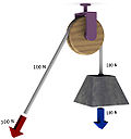
 Movable pulley
 -
 Diagram 2: A movable pulley lifting the load W is supported by two rope parts with tension W/2


These are different types of pulley systems:
- Fixed: A fixed pulley has an axle mounted in bearings attached to a supporting structure. A fixed pulley changes the direction of the force on a rope or belt that moves along its circumference. Mechanical advantage is gained by combining a fixed pulley with a movable pulley or another fixed pulley of a different diameter.
- Movable: A movable pulley has an axle in a movable block. A single movable pulley is supported by two parts of the same rope and has a mechanical advantage of two.
- Compound: A combination of fixed and movable pulleys forms a block and tackle. A block and tackle can have several pulleys mounted on the fixed and moving axles, further increasing the mechanical advantage.
-
 Diagram 3: The gun tackle "rove to advantage" has the rope attached to the moving pulley. The tension in the rope is W/3 yielding an advantage of three
 -
 Diagram 3a: The Luff tackle adds a fixed pulley "rove to disadvantage." The tension in the rope remains W/3 yielding an advantage of three


The mechanical advantage of the gun tackle can be increased by interchanging the fixed and moving blocks so the rope is attached to the moving block and the rope is pulled in the direction of the lifted load. In this case the block and tackle is said to be "rove to advantage."[12] Diagram 3 shows that now three rope parts support the load W which means the tension in the rope is W/3. Thus, the mechanical advantage is three.
By adding a pulley to the fixed block of a gun tackle the direction of the pulling force is reversed though the mechanical advantage remains the same, Diagram 3a. This is an example of the Luff tackle.
Free body diagrams
[edit]The mechanical advantage of a pulley system can be analysed using free body diagrams which balance the tension force in the rope with the force of gravity on the load. In an ideal system, the massless and frictionless pulleys do not dissipate energy and allow for a change of direction of a rope that does not stretch or wear. In this case, a force balance on a free body that includes the load, W, and n supporting sections of a rope with tension T, yields:

The ratio of the load to the input tension force is the mechanical advantage MA of the pulley system,[13]

Thus, the mechanical advantage of the system is equal to the number of sections of rope supporting the load.
Belt and pulley systems
[edit]


A belt and pulley system is characterized by two or more pulleys in common to a belt. This allows for mechanical power, torque, and speed to be transmitted across axles. If the pulleys are of differing diameters, a mechanical advantage is realized.
A belt drive is analogous to that of a chain drive; however, a belt sheave may be smooth (devoid of discrete interlocking members as would be found on a chain sprocket, spur gear, or timing belt) so that the mechanical advantage is approximately given by the ratio of the pitch diameter of the sheaves only, not fixed exactly by the ratio of teeth as with gears and sprockets.
In the case of a drum-style pulley, without a groove or flanges, the pulley often is slightly convex to keep the flat belt centered. It is referred to as a 'crowned' pulley. Though once widely used on factory line shafts, this type of pulley is still found driving the rotating brush in upright vacuum cleaners, in belt sanders and bandsaws.[14] Agricultural tractors built up to the early 1950s generally had a belt pulley for a flat belt (which is what Belt Pulley magazine was named after). It has been replaced by other mechanisms with more flexibility in methods of use, such as power take-off and hydraulics.
Just as the diameters of gears (and, correspondingly, their number of teeth) determine a gear ratio and thus the speed increases or reductions and the mechanical advantage that they can deliver, the diameters of pulleys determine those same factors. Cone pulleys and step pulleys (which operate on the same principle, although the names tend to be applied to flat belt versions and V-belt versions, respectively) are a way to provide multiple drive ratios in a belt-and-pulley system that can be shifted as needed, just as a transmission provides this function with a gear train that can be shifted. V-belt step pulleys are the most common way that drill presses deliver a range of spindle speeds.
With belts and pulleys, friction is one of the most important forces. Some uses for belts and pulleys involve peculiar angles (leading to bad belt tracking and possibly slipping the belt off the pulley) or low belt-tension environments, causing unnecessary slippage of the belt and hence extra wear to the belt. To solve this, pulleys are sometimes lagged. Lagging is the term used to describe the application of a coating, cover or wearing surface with various textured patterns which is sometimes applied to pulley shells. Lagging is often applied in order to extend the life of the shell by providing a replaceable wearing surface or to improve the friction between the belt and the pulley. Notably drive pulleys are often rubber lagged (coated with a rubber friction layer) for exactly this reason.[15] Applying powdered rosin to the belt may increase the friction temporarily, but may shorten the life of the belt.[16]
See also
[edit]- Block (sailing) – Sailing term; single or multiple pulley
- Conveyor pulley
- Deadeye – Item used in rigging of sailing ships
- Differential pulley – Self-balancing mechanical lifting hoist
- Eccentric (mechanism) – Circular disk rigidly fixed to a rotating axle with its center offset from that of the axle
- Hoist – Device used for lifting or lowering a load
- Portsmouth Block Mills – Building in Portsmouth, Hampshire, England
- Reel – Device used to store elongated and flexible objects
- Slickline – Single strand wire which is used to run tools into wellbore
- V-belt – Method of connecting two rotating shafts or pulleys
- Wireline (cabling) – Technology used in oil and gas wells
References
[edit]- ^ Arnold, Dieter (1991). Building in Egypt: Pharaonic Stone Masonry. Oxford University Press. p. 71. ISBN 9780195113747.
- ^ Moorey, Peter Roger Stuart (1999). Ancient Mesopotamian Materials and Industries: The Archaeological Evidence. Eisenbrauns. p. 4. ISBN 9781575060422.
- ^ Usher, Abbott Payson (1988). A History of Mechanical Inventions. USA: Courier Dover Publications. p. 98. ISBN 0-486-25593-X.
- ^ Uicker, John; Pennock, Gordon; Shigley, Joseph (2010). Theory of Machines and Mechanisms (4th ed.). Oxford University Press, USA. ISBN 978-0-19-537123-9.
- ^ Paul, Burton (1979). Kinematics and dynamics of planar machinery (illustrated ed.). Prentice-Hall. ISBN 978-0-13-516062-6.
- ^ Rorres, Chris (2017). Archimedes in the 21st Century. Springer International Publishing. p. 71. ISBN 9783319580593.
- ^ a b MacDonald, Joseph A (14 June 2008). Handbook of Rigging: For Construction and Industrial Operations. McGraw-Hill Professional. p. 376. ISBN 978-0-07-149301-7.
- ^ Prater, Edward L. (1994). "Basic Machines" (PDF). Naval Education and Training Professional Development and Technology Center, NAVEDTRA 14037.
- ^ Bureau of Naval Personnel (1971) [1965]. Basic Machines and How They Work (PDF). Dover Publications. ISBN 0-486-21709-4. Archived from the original (PDF) on 2016-09-22. Retrieved 2011-12-13.
- ^ Avery, Elroy (1878). Elementary physics. Sheldon and company. p. 459.
wheel and axle.
- ^ Bowser, Edward (1890). An elementary treatise on analytic mechanics: With numerous examples (5 ed.). D. Van Nostrand company. p. 180.
- ^ "Seamanship Reference, Chapter 5, General Rigging" (PDF). sccheadquarters.com.
- ^ Tiner, John Hudson (2006-05-01). Exploring the world of physics : from simple machines to nuclear energy. Green Forest, AR: New Leaf Publishing Group. p. 68. ISBN 978-1-61458-156-7. LCCN 2005936557. OCLC 892430550.
- ^ "How crowned pulleys keep a flat belt tracking". Wood Gears.
- ^ "Pulley Lagging". CKIT. Retrieved 17 June 2022.
- ^ "Leather and cotton belts". The English Mechanic and World of Science. No. 1236. London. 30 November 1888. p. 278.