Hubbry Logo
Capacitor discharge ignitionCapacitor discharge ignitionMain
Open search
Capacitor discharge ignition
Community hub
Capacitor discharge ignition
logo
8 pages, 0 posts
0 subscribers
Be the first to start a discussion here.
Capacitor discharge ignition
from Wikipedia
CDI module

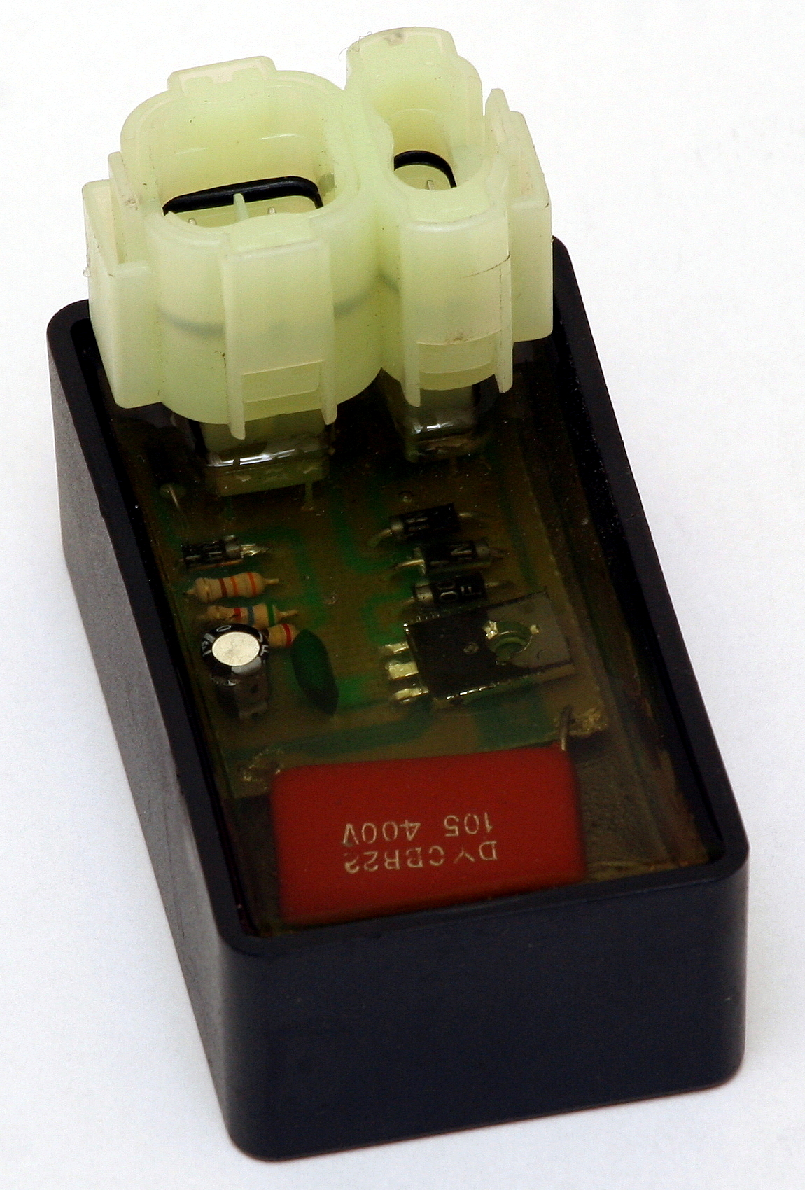
Capacitor discharge ignition (CDI) or thyristor ignition is a type of automotive electronic ignition system which is widely used in outboard motors, motorcycles, lawn mowers, chainsaws, small engines, gas turbine-powered aircraft, and some cars. It was originally developed to overcome the long charging times associated with high inductance coils used in inductive discharge ignition (IDI) systems, making the ignition system more suitable for high engine speeds (for small engines, racing engines and rotary engines). The capacitive-discharge ignition uses capacitor to discharge current to the ignition coil to fire the spark plugs.

History

[edit]

Nikola Tesla

[edit]

The history of the capacitor discharge ignition system can be traced back to the 1890s when it is believed that Nikola Tesla was the first to propose such an ignition system. In U.S. patent 609,250 first filed February 17, 1897, Tesla writes 'Any suitable moving portion of the apparatus is caused to mechanically control the charging of a condenser and its discharge through a circuit in inductive relation to a secondary circuit leading to the terminals between which the discharge is to occur, so that at the desired intervals the condenser may be discharged through its circuit and induce in the other circuit a current of high potential which produces the desired discharge.' The patent also describes very generally with a drawing, a mechanical means to accomplish its purpose.

Ford Model K

[edit]

Originally invented for Henry Fords six cylinder racer in 1905, the first production use of a CDI system was put into use in 1906 as standard equipment with the Ford Model K. The Model K utilized dual ignition systems, one of which was the Holley-Huff Magneto, or Huff System, manufactured by the Holley Brothers Company. It was designed by Edward S. Huff with US patent #882003 filed July 1, 1905 and assigned to Henry Ford. The system used an engine driven DC generator that charged a capacitor and then discharged the capacitor through the ignition coil primary winding. An excerpt from the 'Motorway' Jan 11 1906, describes its use on Ford six cylinder cars: 'The efficiency of the Ford Magneto is shown by the fact that the instant it is switched in the car will pick up speed and, without changing the position of the ignition control lever, will run at least ten miles an hour faster.'

Robert Bosch and the Thyratron

[edit]

It was the Robert Bosch company which was the pioneer of the first electronic CD ignitions. (Bosch is also responsible for the invention of the high-tension magneto.) During World War Two, Bosch had fitted thyratron (tube type) CD ignitions to some piston engined fighter aircraft. With a CD ignition, an aeroplane engine did not need a warm up period for reliable ignition and so a fighter aircraft could take flight more quickly as a result. This early German system used a rotary DC converter along with fragile tube circuitry, and was not suited to life in a fighter aircraft. Failures occurred within only a few hours. The quest for a reliable electronic means of producing a CD ignition began in earnest during the 1950s. In the mid-1950s, the Engineering Research Institute of the University of Michigan in cooperation with Chrysler Corporation in the United States worked to find a method to produce a viable solution.

They were unsuccessful, but did provide much data on the advantages of such a system, should one be built. Namely; a fast voltage rise time to fire fouled or wet spark plugs, high energy throughout the RPM range resulting in better starting, more power and economy, and lower emissions. A few engineers, scientists, and hobbyists had built CD ignitions throughout the 1950s using thyratrons. However, thyratrons were unsuitable for use in automobiles for two reasons. They required a warm-up period which was a nuisance, and were vulnerable to vibration which drastically reduced their service life. In an automotive application, the thyratron CD ignition would fail in weeks or months. The unreliability of those early thyratron CD ignitions made them unsuitable for mass production despite providing short term benefits. One company at least, Tung-Sol (a manufacturer of vacuum tubes) marketed a thyratron CD ignition, model Tung-Sol EI-4 in 1962, but it was expensive. Despite the failings of thyratron CD ignitions, the improved ignition that they gave made them a worthwhile addition for some drivers. For the Wankel powered NSU Spider of 1964, Bosch resurrected its thyratron method for a CD ignition and used this up until at least 1966. It suffered the same reliability problems as the Tung-Sol EI-4.

Thyristor

[edit]

It was the SCR, Silicon-controlled rectifier or thyristor invented in the late 1950s that replaced the troublesome thyratron, and paved the way for a reliable solid-state CD ignition. This was thanks to Bill Gutzwiller and his team at General Electric. The SCR was rugged with an indefinite lifetime, but very prone to unwanted trigger impulses which would turn the SCR 'on'. Unwanted trigger impulses in early attempts at using SCRs for CD ignitions were caused by electrical interference, but the main culprit proved to be 'points bounce'. Points bounce is a feature of a points-triggered system. In the standard system with points, distributor, ignition coil, ignition (Kettering system) points bounce prevents the coil from saturating fully as RPM increases resulting in a weak spark, thus limiting high speed potential. In a CD ignition, at least those early attempts, the points bounce created unwanted trigger pulses to the SCR (thyristor) that resulted in a series of weak, untimed sparks that caused extreme misfiring. There were two possible solutions to the problem. The first would be to develop another means of triggering the discharge of the capacitor to one discharge per power stroke by replacing the points with something else. This could be done magnetically or optically, but that would necessitate more electronics and an expensive distributor. The other option was to keep the points, as they were already in use and reliable, and find a way to overcome the 'points bounce' problem. This was accomplished in April 1962 by a Canadian, RCAF officer F.L. Winterburn working in his basement in Ottawa, Ontario. The design used an inexpensive method that would recognize only the first opening of the points and ignore subsequent openings when the points bounced.

Hyland Electronics

[edit]
F.L. Winterburn

A company was formed in Ottawa in early 1963 called Hyland Electronics building CD ignitions using the Winterburn design. The discharge capacitor within the CD ignition had the ability to provide a powerful spark in excess of 4 times the spark power of the Kettering system using the same coil, with the exception that spark energy could be maintained at high rpm unlike the Kettering system. The Hyland unit consumed only four amperes at 5000rpm (8cyl) or 10,000rpm(4cyl). Dynamometer testing during 1963 and 1964 showed a minimum of 5% increase in horsepower with the system, with 10% the norm. One example, a Ford Falcon, had an increase in horsepower of 17%. Spark plug lifespan was increased to at least 50,000 miles and points lifespan was greatly extended from 8,000 miles to at least 60,000 miles. Points lifespan became a factor of rubbing block (cam follower) wear and the life cycle of the spring with some lasting almost 100,000 miles.

The Hyland unit was tolerant of varied points gaps. The system could be switched back to standard inductive discharge ignition by the swapping of two wires. The Hyland CD ignition was the first commercially produced solid-state CD ignition and retailed for $39.95 Canadian. The patents were applied for by Winterburn on September 23, 1963 (United States patent# 3,564,581). The design was leaked to the United States in the summer of 1963 when Hyland exposed the design to a US company in an effort to expand sales. Afterward, numerous companies started building their own throughout the 1960s and 1970s without licence. Some were direct copies of the Winterburn circuit. In 1971 Bosch bought the European patent rights (German, French, British) from Winterburn.

Wireless World

[edit]

The UK Wireless World magazine of January 1970 published a detailed Capacitor-discharge Ignition system as an electronic hobby build project by R.M. Marston. The circuit of this system was similar to the Winterburn patent in that it used a push-pull converted switch mode oscillator for energy transfer to a store - discharge capacitor and conventional contact breakers to initiate a thyristor triggering discharge of the charged CD capacitor. It was stated to offer several advantages over conventional ignition. Among which: better combustion, easy starting even under subzero conditions, immunity to contactor (points) bounce and 2% - 5% fuel economy. Subsequent letters to Wireless World ( March & May 1970), with Mr. Marston's replies, further discussed aspects of the design and build. In July 1971 Mr. A.P. Harris, undergraduate of the City University London made a detailed electrical engineering analysis of the Marston design as well as automotive engine measurement trials to verify fuel economy. These confirmed the benefits of the CD ignition system. However, he found that the core ingredient of the CD design rested on careful hand winding of the switch mode transformer and appropriate selection of oscillator transistors and choice of oscillator frequency.

Current aftermarket systems

[edit]

For various reasons, probably mostly cost, the majority of currently available aftermarket ignition systems appear to be of the inductive discharge type, although in the 1970s and 1980s a variety of capacitive discharge units were readily available, some retaining the points while others provided an alternative type of timing sensor.

The basic principle

[edit]

Most ignition systems used in cars are inductive discharge ignition (IDI) systems, which are solely relying on the electric inductance at the coil to produce high-voltage electricity to the spark plugs as the magnetic field collapses when the current to the primary coil winding is disconnected (disruptive discharge). In a CDI system, a charging circuit charges a high voltage capacitor, and at the instant of ignition, usually determined by a crank position sensor, the system stops charging the capacitor, allowing the capacitor to discharge its output to the ignition coil before reaching the spark plug.

Typical CDI module

[edit]

A typical CDI module consists of a small transformer, a charging circuit, a triggering circuit and a main capacitor. First, the system voltage is raised to 250 to 600 volts by a power supply inside the CDI module. Then, the electric current flows to the charging circuit and charges the capacitor. The rectifier inside the charging circuit prevents capacitor discharge before the moment of ignition. When the triggering circuit receives the triggering signal, the triggering circuit stops the operation of the charging circuit, allowing the capacitor to discharge its output rapidly to the low inductance ignition coil. In a CD ignition, the ignition coil acts as a pulse transformer rather than an energy storage medium as it does in an inductive system. The voltage output to the spark plugs is highly dependent on the design of the CD ignition. Voltages exceeding the insulation capabilities of existing ignition components can lead to early failure of those components. Most CD ignitions are made to give very high output voltages but this is not always beneficial. When there is no triggering signal the charging circuit is re-connected to charge the capacitor.

Stored energy

[edit]

The amount of energy the CDI system can store for the generation of a spark is dependent on the voltage and capacitance of the capacitors used, but usually it is around 50 mJ, or more. The standard points/coil/distributor ignition, more properly called the inductive discharge ignition system or Kettering ignition system, produces 25mJ at low speed and drops off quickly as speed increases.

One factor often not taken into consideration when discussing CDI spark energy is the actual energy provided to the spark gap versus the energy applied to the primary side of the coil. As a simple example, a typical ignition coil may have a secondary winding resistance of 4000 ohms and a secondary current of 400 milliamperes. Once a spark has struck, the voltage across the spark gap in a running engine drops to a relatively low value, in the order of 1500-2000 volts. This, combined with the fact that the coil secondary current of 400 milliamperes loses approximately 1600 volts through the 4000 ohm secondary resistance means that fully 50% of the energy is lost in heating the coil secondary. Actual measurements show the real world efficiency to be only 35 to 38% when coil primary winding losses are included.

Types

[edit]

Most CDI modules are generally of two types:

AC-CDI

The AC-CDI module obtains its electricity source solely from the alternating current produced by the alternator. The AC-CDI system is the most basic CDI system which is widely used in small engines.

DC-CDI

The DC-CDI module is powered by the battery, and therefore an additional DC/AC inverter circuit is included in the CDI module to raise the 12 V DC to 400-600 V DC, making the CDI module slightly larger. However, vehicles that use DC-CDI systems have more precise ignition timing and the engine can be started more easily when cold.

Similar Non-CDI Ignition Systems

[edit]

Not all small engine ignition systems are CDI. Some engines like older Briggs and Stratton use magneto ignition. The entire ignition system, coil and points, are under the magnetized flywheel.

Another sort of ignition system commonly used on small off-road motorcycles in the 1960s and 1970s was called Energy Transfer. A coil under the flywheel generated a strong DC current pulse as the flywheel magnet moved over it. (If the engine was rotated while examining the wave-form output of the coil with an oscilloscope, it would appear to be AC. However, since the charge-time of the coil corresponds to much less than a full revolution of the crank, the coil really 'sees' only DC current for charging the external ignition coil.) This DC current flowed through a wire to an ignition coil mounted outside of the engine. The points sometimes were under the flywheel for two-stroke engines, and commonly on the camshaft for four-stroke engines. This system worked like all Kettering (points/coil) ignition systems: the opening points trigger the collapse of the magnetic field in the ignition coil, producing a high voltage pulse which flows through the spark plug wire to the spark plug.

Some electronic ignition systems exist that are not CDI. These systems use a transistor to switch the charging current to the coil off and on at the appropriate times. This eliminates the problem of burned and worn points, and provides a hotter spark because of the faster voltage rise and collapse time in the ignition coil.

Advantages and disadvantages of CDI

[edit]

A CDI system has a short charging time, a fast voltage rise (between 3 ~ 10 kV/μs) compared to typical inductive systems (300 ~ 500 V/μs) and a short spark duration limited to about 50-600 μs.[citation needed] The fast voltage rise makes CDI systems insensitive to shunt resistance, but the limited spark duration can for some applications be too short to provide reliable ignition. The insensitivity to shunt resistance and the ability to fire multiple sparks can provide improved cold starting ability.[citation needed]

Since the CDI system provides only a reduced duration spark, it's also possible to combine this ignition system with ionization measurement. This is done by connecting a low voltage (about 80 V) to the spark plug, except when fired. The current flow over the spark plug can then be used to calculate the temperature and pressure inside the cylinder.[citation needed]

References

[edit]
Revisions and contributorsEdit on WikipediaRead on Wikipedia
from Grokipedia
Capacitor discharge ignition (CDI) is a type of electronic ignition system that stores electrical energy in a , which is then rapidly discharged through an to produce a high-voltage spark for igniting the air-fuel mixture in spark-ignition engines. This system, which eliminates mechanical breaker points, relies on solid-state components such as a charge coil or magneto to generate low-voltage , a to convert it to DC, and a storage charged to around 300 volts. A silicon-controlled (SCR) or triggers the discharge at the precise timing determined by engine speed, often via a in digital variants, producing spark voltages up to 40 kV with a short duration of about 0.1 milliseconds. Developed in the late and early as an alternative to conventional inductive ignition systems, CDI technology saw its first commercial unit, the EI-4, introduced in for high-performance automotive applications. By the , it had become widely adopted in small engines, including those in motorcycles, outboard motors, all-terrain vehicles, and , due to its ability to deliver consistent sparks at high RPMs without mechanical wear. In modern digital CDI systems, particularly for two-wheelers, advanced timing control adjusts ignition advance from 0° at low speeds to 25° at high speeds, enhancing , reducing emissions, and preventing engine stalling. Key advantages of CDI include increased spark (typically 20-40 millijoules), longer life (up to four to five times that of conventional systems), easier cold starts, and resistance to environmental factors like moisture, as the sealed solid-state design requires no adjustments or point replacements. While early CDI units used battery power with DC-DC converters, magneto-based versions generate their own , making them ideal for portable applications. The system's short spark (10-30 microseconds) excels in high-compression and high-output engines, firing fouled plugs effectively and operating under pressures up to three times higher than inductive systems.

Fundamentals

Basic Principle

Capacitor discharge ignition (CDI) is an electronic ignition method that generates a high-voltage spark for igniting the air-fuel in internal combustion engines by rapidly discharging a pre-charged through the primary winding of an . In this system, the is charged to a voltage typically ranging from 250 to 600 volts DC, storing electrical energy that is then released in a short, intense pulse to induce a secondary voltage of 20-30 kV across the spark plug gap. This discharge creates a powerful spark capable of reliable ignition even under high engine speeds or fouled plug conditions. Unlike traditional inductive ignition systems, which rely on the collapse of a in the coil to generate voltage, CDI utilizes the stored electrostatic in the for spark production, enabling faster transfer and reduced dependence on speed for performance. Inductive systems build gradually through current buildup in the coil's primary, resulting in slower spark characteristics, whereas CDI's -based approach delivers a near-instantaneous , improving efficiency at elevated RPMs. The basic circuit configuration places the charged in series with the primary winding of the , with discharge initiated by a switch, such as a (SCR), triggered at the precise timing determined by engine position signals. This setup ensures the 's is dumped quickly into the coil, producing a secondary voltage with a rapid rise rate of 3-10 kV/μs, which is significantly faster than the 0.3-0.5 kV/μs typical of inductive systems and essential for effective spark kernel formation. The foundational physics of CDI centers on electrostatic in the , governed by the equation E=12CV2E = \frac{1}{2} C V^2 where EE is the stored energy in joules, CC is the in farads, and VV is the charging voltage in volts; for example, a 0.2 μF charged to 600 V yields approximately 36 mJ of energy available for spark generation. This quadratic relationship highlights how higher voltages disproportionately increase available energy, optimizing CDI for compact, high-output designs without bulky inductors.

Key Components

The capacitor discharge ignition (CDI) system relies on several core hardware elements to store, switch, and transform electrical into a high-voltage spark for ignition. These components are typically integrated into a compact module to ensure reliability in harsh automotive environments. At the heart of the system is the high-voltage , which stores the energy needed for spark generation. This component usually has a ranging from 0.1 to 1 μF and is rated for voltages between 400 and 600 V to handle the rapid charging and discharge cycles without breakdown. It is often constructed with metallized for high stability and low losses during operation. The functions as a pulse transformer, stepping up the low-voltage discharge from the to the required at the . Its primary winding typically exhibits an of 1 to 5 mH, enabling quick energy transfer without excessive ringing, while the secondary winding produces output voltages of 20 to 40 kV to ionize the . Primary resistance is commonly around 0.4 to 1.8 ohms, and secondary resistance ranges from 5 to 15 kΩ, optimized for short-duration s rather than sustained . Switching is managed by the triggering device, such as a (silicon-controlled rectifier, SCR) or similar semiconductor switch like an IGBT or , which rapidly connects the charged to the ignition coil's primary upon receiving a timing signal. This device ensures precise control, with the gate triggered by a low-voltage to initiate discharge at the optimal position. The charging circuit elevates the input from a low-voltage source, such as a 6-12 V battery or , to the capacitor's rated voltage using a step-up , DC-DC converter, or dedicated charging coil. It includes rectification to convert AC to DC and prevent back-discharge, often producing 250-400 V for stable operation independent of engine speed. The triggering circuit generates the timing signal for the switching device, typically employing a pickup coil or to detect or position. This sensor outputs a low-voltage (around 6 AC) that is processed to fire the gate, ensuring spark timing aligns with engine requirements. In typical implementations, these elements are assembled into a compact PCB module within a sealed CDI box, providing electrical isolation for high-voltage sections and protection against vibration and moisture in aftermarket or OEM units. This integration allows for straightforward installation and maintenance in small engines like those in motorcycles and outboard motors.

Types of CDI Systems

AC-CDI

AC-CDI, or alternating current capacitor discharge ignition, is a variant of CDI systems that relies on the engine's flywheel alternator or magneto to generate the necessary power for capacitor charging, eliminating the need for a separate battery. This design harnesses the alternating current produced by the rotating magnets in the flywheel assembly as the engine operates, providing a self-contained power source suitable for compact applications, particularly in two-stroke engines. In the circuit, rectifier diodes play a crucial role by converting the incoming AC voltage from the into pulsating DC, which charges the to high voltages typically ranging from 200 to 400 V. This rectification process ensures unidirectional current flow into the capacitor, preventing reverse charging during AC waveform negative cycles and simplifying the overall architecture by obviating the need for an inverter or external power conversion stages. The resulting setup reduces component count and enhances reliability in harsh operating environments. Timing in AC-CDI systems is achieved through phase detection from the alternator windings, where a dedicated pulser coil or pickup generates a trigger signal aligned with the engine's position. This signal initiates the or SCR discharge of the into the at the optimal moment, synchronizing spark timing with engine rotation without additional sensors. These systems are commonly implemented in two-stroke motorcycles, such as Yamaha models, and small engines like chainsaws, where space constraints and the absence of a battery favor their lightweight, integrated design. Performance characteristics include voltage output that scales with engine RPM, delivering consistent high-speed sparks but potentially weaker ignition at low speeds due to reduced output. This RPM-dependent behavior makes AC-CDI particularly effective for applications emphasizing high-revving operation over idle stability.

DC-CDI

DC-powered capacitor discharge ignition (DC-CDI) systems draw electrical power from a standard 12V battery, employing a DC-AC inverter—typically consisting of an oscillator and step-up —to generate high-voltage charging pulses for the storage . This inverter converts the low-voltage DC input into , which is then rectified back to DC at elevated levels, ensuring the capacitor charges efficiently without reliance on engine-generated . Unlike AC-CDI variants, this battery-dependent approach provides a stable power source unaffected by engine speed variations and is commonly used in four-stroke engines such as motorcycles and scooters. The core circuit of a DC-CDI includes the inverter producing approximately 300-400V DC pulses to charge the main , often supplemented by a to maintain consistent output regardless of battery fluctuations or RPM. The charged then discharges rapidly through a silicon-controlled (SCR) into the primary winding of the , generating the high-voltage spark needed for . This design incorporates electronic timing controls, such as microprocessors or analog circuits, enabling programmable ignition advance curves that optimize timing based on load, RPM, and other parameters for enhanced and . DC-CDI systems are commonly implemented in four-stroke engines like and scooters, as well as in outboard —such as post-1980s models from manufacturers like Mercury—and high-performance applications demanding reliable spark delivery. These systems deliver a consistent charge of around 300-400V, contributing to superior low-RPM starting capability and improved operation in cold weather conditions due to the stable, battery-sourced power and accurate timing. The independence from output ensures robust performance across a wide range of operating conditions, making DC-CDI particularly suitable for applications requiring reliability in variable environments.

Configurations for 2-Cylinder and 4-Cylinder Motorcycle Engines

CDI systems for motorcycles are designed specifically for the engine's cylinder count and configuration. In 4-cylinder engines, the CDI typically manages ignition across all four cylinders using a wasted spark system with two ignition coils. Each coil fires a paired set of cylinders simultaneously (such as cylinders 1-4 and 2-3), where one cylinder receives a spark during its compression stroke (useful for combustion) while the paired cylinder receives a spark during its exhaust stroke (wasted). In contrast, 2-cylinder (twin) engines generally use one or two coils in a wasted spark configuration, often firing both cylinders together or in accordance with the engine's firing order. These differences in coil arrangements, firing orders, ignition timing curves, and required sensor inputs render CDI units model-specific and non-interchangeable across different engine configurations or cylinder counts, as variations in ignition management requirements prevent compatibility between systems designed for different setups.

Historical Development

Early Concepts and Patents

The concept of capacitor discharge ignition (CDI) originated in the late as an innovative method to generate high-voltage sparks for internal combustion engines using stored in a condenser. laid the foundational patent for this approach in U.S. Patent 609,250, filed on February 17, 1897, and granted on August 16, 1898, titled "Electrical Igniter for Gas-Engines." In this invention, Tesla described a system where a condenser is charged from a battery or via a circuit-closing switch and then discharged through the primary winding of an , producing a powerful, rapid spark across separated terminals in the engine's explosive chamber. This design emphasized the condenser's role in delivering an instantaneous discharge for reliable ignition, addressing limitations in contemporary low-intensity spark systems. An early practical implementation of CDI principles appeared in the automotive domain with the 1906 Ford Model K, a six-cylinder vehicle designed for high-performance applications. Edward S. Huff, a self-taught electrical working closely with , developed the patented under U.S. 882,003, filed on July 1, 1905, and assigned to . The Huff system utilized an engine-driven DC generator (magneto) to charge a , which was then discharged mechanically to create consistent, high-energy sparks suitable for the engine's elevated RPMs, enhancing reliability during conditions. This marked one of the first production uses of CDI in a , prioritizing faster spark timing over conventional inductive methods for improved at speed. However, these pioneering efforts encountered significant technical hurdles that hindered broader adoption. Mechanical switches responsible for controlling the condenser's charge and discharge were susceptible to severe arcing from the high-voltage transients, leading to rapid contact erosion and inconsistent performance. The wear from repeated arcing not only shortened component lifespan but also introduced timing inaccuracies, making the systems unreliable for everyday or prolonged high-speed operation. These limitations underscored a key conceptual evolution in ignition design: moving away from vibration-prone contact-breaker mechanisms toward more precise discharge control to achieve quicker, hotter sparks essential for advancing and speed. Early CDI thus represented a theoretical leap, though practical viability awaited refinements in switching technology.

Mid-20th Century Innovations

In the post-war period, efforts to adapt CDI for automotive use gained momentum in the 1950s. Corporation experimented with CDI systems to improve ignition reliability over traditional breaker-point mechanisms. These initiatives focused on overcoming the limitations of early electronic switches, paving the way for practical implementation. A major breakthrough came with the introduction of the silicon-controlled rectifier (SCR), or , by in 1957, which replaced the unreliable tubes with solid-state devices capable of handling high voltages and currents more durably. In 1963, F.L. Winterburn filed a for an SCR-based CDI design (U.S. Patent 3,564,581, granted 1971) that addressed points bounce by using a and to trigger the electronic switch cleanly, preventing unwanted misfires. This innovation significantly enhanced system stability. The shift to SCRs enabled fully solid-state CDI operation, reducing mechanical wear and maintenance needs compared to earlier tube-based or contact-dependent systems, marking a key step toward widespread automotive adoption.

Commercialization and Aftermarket Adoption

The Tung-Sol EI-4, introduced in 1962 by Motion Inc. using a tube design, marked the first commercial CDI unit for high-performance automotive applications. Hyland Electronics, established in , , in 1963, became the first company to commercialize solid-state capacitor discharge ignition (CDI) systems by producing units based on F.L. Winterburn's SCR design. These early production models offered improved spark characteristics that extended life by at least five times compared to conventional points-based systems and provided a modest 3-4% horsepower increase on mildly tuned engines. In the late 1960s and early , DIY enthusiasts contributed to CDI's grassroots adoption through accessible designs published in technical magazines. For instance, R.M. Marston detailed a capacitor-discharge in the January 1970 issue of Wireless World, enabling hobbyists to build their own units using readily available components. This DIY accessibility spurred aftermarket interest, particularly among and owners seeking reliability upgrades. By the 1970s, CDI systems gained significant traction in the aftermarket for and outboard boat engines, where their resistance to moisture and vibration proved advantageous over mechanical points ignitions. Adoption accelerated with products like the 1969 Kawasaki Mach III, one of the first production to feature electronic CDI. Modern aftermarket offerings, such as MSD Performance's Digital 6AL CDI boxes, continue this legacy in racing applications, incorporating adjustable RPM limiters to protect engines during high-speed operation and delivering up to 135 mJ of spark energy. The 1980s saw CDI transition from aftermarket novelty to standard (OEM) integration, especially in Japanese motorcycles. Honda's CB series, including models like the CB750 and CB900 from 1979-1983, widely adopted CDI modules for their dual-unit setups that enhanced starting reliability and performance in multi-cylinder engines. This OEM shift solidified CDI's role in mainstream powersports, reducing maintenance needs and supporting the era's emphasis on electronic engine management.

Operation and Energy Management

Charging Process

In capacitor discharge ignition (CDI) systems, the charging process begins with power input from either low-voltage alternating current (AC) generated by an engine's alternator or stator winding, typically around 6-12V AC, or direct current (DC) from a battery, often 12V in DC-CDI variants. This low-voltage source feeds into a step-up transformer, which boosts the voltage through its secondary windings to produce high-voltage pulses suitable for capacitor charging, often reaching intermediate levels before final storage. The high-voltage pulses undergo rectification via diodes arranged in a bridge or half-wave configuration to ensure unidirectional current flow, converting the AC pulses into positive DC for efficient charging while blocking reverse polarity that could damage components. The rectified voltage is then directed to the storage capacitor, where it accumulates charge according to the circuit's time constant τ = RC, with R representing the charging (or equivalent impedance) that limits current to prevent excessive stress, and C the value, typically determining a charge rate that allows buildup in milliseconds. Voltage buildup in the occurs rapidly, reaching 250-600V within 1-2 ms per cycle, synchronized to the position via a trigger signal from a pickup coil or that monitors rotation. This timing ensures charging aligns with the engine's ignition needs, and an interrupt mechanism—activated by the trigger signal—opens the charging path through a switch like a silicon-controlled rectifier (SCR), halting further accumulation just before the discharge phase to avoid overvoltage. Efficiency in the charging process is influenced by losses primarily in the step-up (due to core and winding resistances) and diodes (from forward voltage drops), typically accounting for 20-30% of input energy dissipation, resulting in overall system efficiencies around 70% at high engine speeds. These losses are minimized in designs using constant-current charging circuits, which maintain steady buildup rates even under varying loads.

Discharge Mechanism

The discharge mechanism in capacitor discharge ignition (CDI) systems begins with trigger initiation, where a , such as a or inductive pickup, detects the piston's position near top dead center and generates a precise pulse to the thyristor gate. This pulse, typically lasting a few microseconds, rapidly closes the switch in less than 1 μs, initiating the discharge process. The , functioning as a high-power switch, allows the stored charge to flow unimpeded once triggered. Upon triggering, the rapidly dumps its charge through the primary winding of the , creating a sudden change in that induces a high-voltage in the secondary winding via mutual . The secondary voltage is given by Vsecondary=NdΦdtV_{\text{secondary}} = N \cdot \frac{d\Phi}{dt}, where NN is the turns ratio and dΦdt\frac{d\Phi}{dt} is the rate of change of , typically resulting in 20-40 kV across the gap. This energy transfer occurs almost instantaneously, producing a high-current in the primary circuit up to 100 A. The resulting spark at the plug exhibits short duration characteristics, lasting 50-100 μs, which enables quick and efficient ignition of the air-fuel mixture, particularly beneficial at high speeds. This brief, intense discharge contrasts with longer-duration sparks in other systems, prioritizing rapid energy delivery over sustained arcing. After the capacitor's energy is depleted, the self-commutates and turns off due to current reversal induced by the coil's inductive ringing, which applies a reverse voltage across the device and drops the anode current below the holding level. This natural resets the circuit for the next cycle without external intervention. Timing precision in the discharge is achieved through adjustable dwell control, where the interval between sensor detection and triggering is optimized—often via digital microcontrollers—for ideal phasing across varying engine conditions like RPM and load.

Stored Energy Characteristics

The stored in a discharge ignition (CDI) system is governed by the fundamental for electrostatic in a , E=12CV2E = \frac{1}{2} C V^2, where EE is the in joules, CC is the in farads, and VV is the voltage across the in volts. In CDI applications, this is pre-charged into the main discharge , typically ranging from 0.47 to 2.2 μF, and charged to voltages between 400 and 630 V, yielding stored energies of 50–100 mJ for standard single-cylinder systems. For example, a 1 μF charged to 400 V stores approximately 80 mJ, providing a rapid discharge capable of generating high-voltage sparks for ignition. Compared to inductive discharge systems, CDI delivers higher peak power during spark generation due to its fast energy release, but the discharge duration is shorter, often tens to hundreds of microseconds versus 1–2 milliseconds for inductive systems. Inductive systems typically store and deliver around 25 mJ at low engine RPM, with energy output decreasing rapidly at higher speeds due to limited dwell time. This contrast highlights CDI's advantage in high-RPM scenarios, where its consistent energy delivery supports reliable ignition without significant drop-off. Energy transfer from the stored charge to the spark output accounts for losses primarily in the during discharge, where resistive heating and magnetic inefficiencies convert a portion of the stored to ; in typical designs, only about 15 mJ of a 100 mJ stored charge reaches the . These coil losses necessitate robust heat dissipation in components like the transformer windings to prevent thermal degradation. For scalability, CDI systems can be engineered for higher energies up to 200 mJ or more in variants using larger capacitances or elevated voltages, enabling support for multi-cylinder engines where simultaneous or sequential firing demands greater total output without compromising per-cylinder performance. Such configurations maintain the core principle of rapid discharge while adapting to increased power requirements. Stored and discharge characteristics in CDI are commonly measured using traces of voltage and current waveforms across the and coil, allowing direct calculation of delivered via integration of the power curve (voltage × current over time). These traces reveal the sharp voltage rise (3–10 kV/μs) and oscillatory decay, confirming efficient transfer metrics in real-time testing.

Applications

Traditional Uses in Vehicles and Engines

Capacitor discharge ignition (CDI) systems saw early adoption in the automotive sector during the and , primarily as aftermarket upgrades for performance vehicles. Introduced by Delco-Remy in as a production option for models like the and Pontiac, CDI provided a stronger, hotter spark through rapid discharge, enhancing high-RPM operation and cold-start reliability compared to traditional breaker-point systems. These systems gained popularity among enthusiasts for muscle cars, including the , where aftermarket CDI kits were favored for their ability to fire fouled plugs and support modified engines in hot rods and racing applications. In the motorcycle industry, CDI became a standard feature in Japanese two-stroke engines by the , driven by manufacturers like Yamaha, , and Kawasaki to meet demands for lightweight, high-revving powersports machines. This shift from points-based ignitions allowed for more precise timing control and consistent sparking in compact, high-output two-stroke designs prevalent in off-road and street-legal bikes of the era. Marine applications leveraged CDI's robustness in outboard motors, particularly from brands like Johnson and Evinrude, where it ensured reliable high-RPM sparking in harsh, wet conditions starting from the . The system's solid-state design, often encapsulated for moisture resistance, supported consistent ignition in saltwater environments and under varying loads typical of , replacing less durable points systems for better in two- and four-stroke outboards. For small engines in recreational and utility equipment, AC-CDI variants offered simplicity and self-sufficiency without needing a battery, making them ideal for lawnmowers, all-terrain vehicles (ATVs), and snowmobiles. In snowmobiles, for instance, brands like transitioned to CDI around 1982 for models such as the Citation and , providing dependable operation in cold, high-vibration settings with minimal maintenance. In these traditional contexts, CDI contributed to extended spark plug life by delivering a more efficient, multi-spark discharge that reduced fouling and electrode wear, often allowing plugs to last significantly longer than in inductive systems. In racing applications across automotive and powersports, it enabled 5-10 mph top-speed gains through optimized and stronger sparks, supporting higher compression and without major engine modifications. By the , CDI had achieved dominance in the powersports market, becoming the for motorcycles, ATVs, and snowmobiles due to its reliability and performance in high-revving, compact engines.

Modern and Specialized Applications

In the 2010s and beyond, microcontroller-based CDI systems have been integrated into electronic (EFI) setups for motorcycles, enabling precise synchronized with engine parameters via CAN-bus networks. These digital CDI units, often employing microcontrollers like the PIC18F6627 operating at 40 MHz, support programmable timing maps and compatibility with EFI kits to optimize combustion efficiency and emissions control. For instance, systems such as the SportDevices programmable CDI use for adjustable spark delays based on RPM, allowing seamless adaptation to modern EFI demands without mechanical distributors. High-energy CDI variants find specialized use in racing and aviation applications where reliable spark delivery is critical under extreme conditions. In drag racing, the MSD 7AL-2 Plus ignition control delivers superior spark energy—up to 160 mJ per firing—with built-in two-step rev limiting and adjustable output curves tailored for short-duration, high-RPM runs, making it a preferred choice for nitro-fueled and boosted engines. Similarly, in light aircraft, CDI systems like Light Speed Engineering's Plasma series provide robust performance at altitude by generating hot sparks exceeding 130 mJ at up to 40,000 volts, with automatic timing adjustments for manifold pressure and RPM to maintain power and fuel efficiency across varying atmospheric conditions. These solid-state designs eliminate moving parts, enhancing reliability in environments where magneto systems may falter due to lower spark intensity. CDI technology has also been adapted for unmanned aerial vehicles (UAVs) and drones, where compact, lightweight ignition is essential for small internal engines. Programmable CDI units, such as those from Ecotrons, weigh only 120 grams and support single- or dual-channel operation in engines from 20cc to 600cc, integrating with ECUs for precise control and high reliability in rotary or multi-cylinder configurations. These systems enable efficient fuel in hybrid drone designs, contributing to extended flight times without significantly increasing payload. Additionally, some advanced CDI implementations incorporate ionization current sensing through the gap to detect misfires in real-time, supporting closed-loop feedback for engine diagnostics in constrained applications. To meet evolving automotive standards, modern CDI systems in vehicles emphasize electromagnetic interference (EMI) shielding, aligning with 2025 regulations like CISPR 25 Class 5 limits for radiated and . Shielded high-tension cables and grounded enclosures minimize interference from spark events, ensuring compatibility with sensitive such as ADAS and systems. This focus on EMI mitigation has driven design enhancements, including conductive braiding on ignition leads, to maintain system integrity in increasingly electrified powertrains.

Comparisons with Other Ignition Systems

Inductive Discharge Systems

Inductive discharge ignition systems, also known as conventional or ignition systems, operate on the principle of to generate high-voltage sparks for engine combustion. A low-voltage current from the battery flows through the primary winding of the , building a strong around the coil's iron core. This current is interrupted by a (in older mechanical systems) or a (in electronic variants), causing the to collapse rapidly and induce a high-voltage pulse in the secondary winding via . The resulting voltage is directed to the spark plugs to ignite the air-fuel mixture. Key components include the ignition coil, which stores energy magnetically; a distributor that routes the high-voltage output to the correct spark plug based on engine position; and dwell control mechanisms, such as adjustable points or electronic timing circuits, which regulate the charging time of the primary coil to ensure sufficient magnetic buildup before discharge. Typical stored energy in these systems ranges from 25 to 50 millijoules, calculated as the magnetic energy E=12LI2E = \frac{1}{2} L I^2, where LL is the primary inductance and II is the primary current. These systems produce sparks with a longer duration of 1 to 2 milliseconds and lower peak voltages of 15 to 25 kilovolts, providing sustained arc energy suitable for reliable ignition under normal conditions. Developed by and first installed in a in 1911, with patent issuance in 1915, the inductive system became the dominant automotive ignition technology from the through the , powering the transition from hand-cranked to electric-start vehicles. Limitations include mechanical wear on points due to arcing during interruption, necessitating periodic replacement, and a slower voltage of approximately 1 kV/μs, which can reduce spark intensity in high-compression or fouled-plug scenarios. In contrast to capacitor discharge ignition (CDI) systems, inductive systems deliver energy through prolonged magnetic collapse rather than rapid capacitive dumping.

Magneto and Similar Non-CDI Systems

Magneto ignition systems function through , employing a permanent rotor that rotates within or around a coil assembly to generate without any need for external electrical power sources. This self-contained design relies on the engine's mechanical rotation—typically driven by the or —to induce a changing in the primary coil windings, producing a low-voltage current that builds a . When breaker points or an equivalent switching mechanism interrupt this current, the collapsing induces a high-voltage (often up to 20,000 volts) in the secondary coil windings, which is then directed to the spark plugs to create the ignition spark. Variants of magneto systems include energy transfer configurations commonly used in small engines, such as those developed by , where magnets embedded in the engine pass by the coil armature to generate the necessary current, often in conjunction with mechanical points or solid-state switches for timing control. These systems transfer directly from the 's rotation to the , enabling simple, compact designs suitable for portable equipment without batteries or alternators. In such setups, the 's magnets induce voltage in the armature coil as they approach and recede, with the points opening at the optimal moment to release the stored energy as a spark. Key characteristics of magneto systems include relatively low spark energy output, typically in the range of 30-50 mJ per discharge, which varies directly with engine RPM due to the dependence on rotational speed for generation. This RPM-dependent performance results in weaker sparks at low speeds but stronger output at higher RPMs, making magnetos reliable for steady-state operation once the engine is running. They are widely applied in small engines like those in lawnmowers, chainsaws, and generators, as well as in reciprocating engines, where dual-magneto setups provide redundancy for safety. The evolution of magneto systems in the introduced transistorized variants, replacing mechanical breaker points with solid-state switches to improve reliability and reduce , though these remained fundamentally inductive in operation. For instance, early electronic magnetos used transistors to control current flow in the primary coil, enhancing durability in harsh environments. In contrast to capacitor discharge ignition (CDI) systems, magnetos do not employ capacitors for ; instead, they rely on magnetic saturation within the to build and release energy, resulting in longer-duration but lower-peak sparks without the rapid discharge characteristic of CDI.

Advantages and Limitations

Benefits of CDI

Capacitor discharge ignition (CDI) systems excel in high-speed operation due to their rapid spark voltage , typically ranging from 3 to 10 kV/µs, which significantly outpaces the 0.3 to 0.5 kV/µs of inductive systems. This fast ensures reliable ignition kernel formation and flame propagation at elevated RPMs, where dwell time is limited, resulting in improved efficiency. A key durability advantage of CDI lies in its solid-state design, which eliminates mechanical breaker points prone to wear, arcing, and frequent adjustments found in conventional systems. This leads to extended spark plug life—often doubling or more compared to points-based ignitions—and substantially reduced maintenance requirements, enhancing overall system reliability in demanding environments like marine or automotive engines. CDI facilitates easier engine starting, particularly in cold conditions, by delivering consistent high-energy sparks insensitive to increased resistance from fouled or wet plugs. The system's ability to produce sparks across oil-contaminated or rich mixtures prevents misfires, ensuring smoother cold starts and reliable operation without the need for plug cleaning or replacement as often as with inductive setups. In modern engine control units (ECUs), CDI supports advanced diagnostics through ionization current measurement, where post-spark ion flow in the is monitored to detect knock events accurately and adjust timing in real-time. This feature improves engine protection and without additional sensors. Additionally, CDI's design accommodates multi-spark modes, firing multiple sparks per cycle to enhance low-RPM stability and contribute to gains of 3.5% to 6% in tested engines by enabling leaner mixtures and better burn completeness.

Drawbacks and Challenges

One significant limitation of capacitor discharge ignition (CDI) systems is the short duration of the spark, typically ranging from 50 to 600 microseconds, which can restrict effective energy transfer in large engines and lead to misfires under high load or lean mixture conditions. This brevity contrasts with longer-duration sparks in alternative systems, potentially compromising reliability in demanding applications such as high-displacement marine or industrial engines. CDI systems are prone to () due to their high rate of voltage change (dV/dt), which generates noise that can disrupt onboard electronics, particularly in modern vehicles equipped with sensitive control modules and sensors as of 2025. Mitigation often requires additional shielding and filtering components to prevent signal degradation in communication systems or engine management units. The design of CDI involves more complex electronics compared to simpler inductive systems, increasing manufacturing costs and elevating the risk of failure from component degradation, notably capacitor aging due to chemical breakdown and thermal stress. Capacitors in these units typically exhibit reduced performance after several years of operation, with lifespan influenced by environmental factors like vibration and temperature, often lasting 20-30 years or more on average, though reduced in harsh conditions. Safety challenges arise from the high-voltage output of CDI systems, which poses risks of electrical shocks to technicians during and can result in sudden no-start failures if components fail, critical in applications like where stranding could endanger users. Proper grounding and insulated tools are essential to address these hazards. In AC-powered CDI variants, voltage supply varies with RPM, leading to inconsistent performance at low speeds where output is insufficient, often requiring supplementary rev limiters or regulators to avoid over-revving or erratic . This variability can exacerbate starting difficulties in low-RPM scenarios without additional circuitry for stabilization.

References

Add your contribution
Related Hubs
User Avatar
No comments yet.