Hubbry Logo
Deep drawingDeep drawingMain
Open search
Deep drawing
Community hub
Deep drawing
logo
8 pages, 0 posts
0 subscribers
Be the first to start a discussion here.
Deep drawing
Deep drawing
from Wikipedia
Example of deep drawn parts

Deep drawing is a sheet metal forming process in which a sheet metal blank is radially drawn into a forming die by the mechanical action of a punch.[1] It is thus a shape transformation process with material retention. The process is considered "deep" drawing when the depth of the drawn part exceeds its diameter. This is achieved by redrawing the part through a series of dies.

The flange region (sheet metal in the die shoulder area) experiences a radial drawing stress and a tangential compressive stress due to the material retention property. These compressive stresses (hoop stresses) result in flange wrinkles (wrinkles of the first order). Wrinkles can be prevented by using a blank holder, the function of which is to facilitate controlled material flow into the die radius. Deep drawing presses, especially in the Aerospace and Medical industries, require unparalleled accuracy and precision. Sheet hydroforming presses do complex draw work. Bed size, tonnage, stroke, speed, and more can be tailored to your specific draw forming application.

Process

[edit]

The total drawing load consists of the ideal forming load and an additional component to compensate for friction in the contacting areas of the flange region and bending forces as well as unbending forces at the die radius. The forming load is transferred from the punch radius through the drawn part wall into the deformation region (sheet metal flange). In the drawn part wall, which is in contact with the punch, the hoop strain is zero whereby the plane strain condition is reached. In reality, mostly the strain condition is only approximately plane. Due to tensile forces acting in the part wall, wall thinning is prominent and results in an uneven part wall thickness, such that the part wall thickness is lowest at the point where the part wall loses contact with the punch, i.e., at the punch radius.

The thinnest part thickness determines the maximum stress that can be transferred to the deformation zone. Due to material volume constancy, the flange thickens and results in blank holder contact at the outer boundary rather than on the entire surface. The maximum stress that can be safely transferred from the punch to the blank sets a limit on the maximum blank size (initial blank diameter in the case of rotationally symmetrical blanks). An indicator of material formability is the limiting drawing ratio (LDR), defined as the ratio of the maximum blank diameter that can be safely drawn into a cup without flange to the punch diameter. Determination of the LDR for complex components is difficult and hence the part is inspected for critical areas for which an approximation is possible. During severe deep drawing the material work hardens and it may be necessary to anneal the parts in controlled atmosphere ovens to restore the original elasticity of the material.

Commercial applications of this metal shaping process often involve complex geometries with straight sides and radii. In such a case, the term stamping is used in order to distinguish between the deep drawing (radial tension-tangential compression) and stretch-and-bend (along the straight sides) components. Deep drawing is always accompanied by other forming techniques within the press. These other forming methods include:[2]

  • Beading: Material is displaced to create a larger, or smaller, diameter ring of material beyond the original body diameter of a part, often used to create O-ring seats.
  • Bottom Piercing: A round or shaped portion of metal is cut from the drawn part.
  • Bulging: In the bulging process a portion of the part's diameter is forced to protrude from the surrounding geometry.
  • Coining: Material is displaced to form specific shapes in the part. Typically coining should not exceed a depth of 30% of the material thickness.
  • Curling: Metal is rolled under a curling die to create a rolled edge.
  • Extruding: After a pilot hole is pierced, a larger diameter punch is pushed through, causing the metal to expand and grow in length.
  • Ironing / Wall Thinning: Ironing is a process to reduce the wall thickness of parts. Typically ironing should not exceed a depth of 30% of the material thickness.
  • Necking: A portion of the part is reduced in diameter to less than the major diameter.
  • Notching: A notch is cut into the open end of the part. This notch can be round, square, or shaped.
  • Rib Forming: Rib forming involves creating an inward or outward protruding rib during the drawing process.
  • Side Piercing: Holes are pierced in the side wall of the drawn part. The holes may be round or shaped according to specifications.
  • Stamping / Marking: This process is typically used to put identification on a part, such as a part number or supplier identification.
  • Threading: Using a wheel and arbor, threads are formed into a part. In this way threaded parts can be produced within the stamping press.
  • Trimming: In the Trimming process, excess metal that is necessary to draw the part is cut away from the finished part.

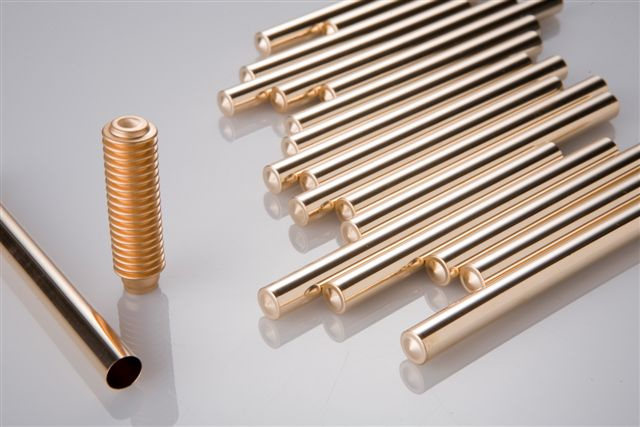
Often components are partially deep drawn in order to create a series of diameters throughout the component (as in the image of the deep draw line). It common use to consider this process as a cost saving alternative to turned parts which require much more raw material.

Example of deep drawn line

The sequence of deep drawn components is referred to as a "deep draw line". The numbers of components that form the deep draw line is given by the quantity of "stations" available in the press. In the case of mechanical presses this is determined by the number of cams on the top shaft.

For high precision mass productions, it is always advisable to use a transfer press also known as eyelet press. The advantage of this type of press, in respect to conventional progressive presses, is that the parts are transferred from one die to the next by means of so-called "fingers". Not only do the fingers transfer the parts but they also guide the component during the process. This allows parts to be drawn to the deepest depths with the tightest tolerances.

Other types of presses:[3]

  • Die-Set Transfer Press: Part is transferred via transfer fingers as the part progresses through the forming process. Tooling components attached to die plates enable the die to be installed in the press as one unit.
  • ICOP (Individually Cam Operated Press): The part is transferred via transfer fingers as the part progresses through the forming process. Die components are installed in the press one station at a time.
  • Progressive Die Press: The part is carried on the steel webbing as it progresses through the forming process.

Variations

[edit]

Deep drawing has been classified into conventional and unconventional deep drawing. The main aim of any unconventional deep drawing process is to extend the formability limits of the process. Some of the unconventional processes include hydromechanical deep drawing, Hydroform process, Aquadraw process, Guerin process, Marform process and the hydraulic deep drawing process to name a few.

The Marform process, for example, operates using the principle of rubber pad forming techniques. Deep-recessed parts with either vertical or sloped walls can be formed. In this type of forming, the die rig employs a rubber pad as one tool half and a solid tool half, similar to the die in a conventional die set, to form a component into its final shape. Dies are made of cast light alloys and the rubber pad is 1.5-2 times thicker than the component to be formed. For Marforming, single-action presses are equipped with die cushions and blank holders. The blank is held against the rubber pad by a blank holder, through which a punch is acting as in conventional deep drawing. It is a double-acting apparatus: at first the ram slides down, then the blank holder moves: this feature allows it to perform deep drawings (30-40% transverse dimension) with no wrinkles.[4][5][6][7][8]

Industrial uses of deep drawing processes include automotive body and structural parts, aircraft components, utensils and white goods. Complex parts are normally formed using progressive dies in a single forming press or by using a press line.

Workpiece materials and power requirements

[edit]

Softer materials are much easier to deform and therefore require less force to draw. The following is a table demonstrating the draw force to percent reduction of commonly used materials.

Drawing force required for various materials and reductions [kN][9]
Material Percent reduction
39% 43% 47% 50%
Aluminium 88 101 113 126
Brass 117 134 151 168
Cold-rolled steel 127 145 163 181
Stainless steel 166 190 214 238

Tool materials

[edit]

Punches and dies are typically made of tool steel, however cheaper (but softer) carbon steel is sometimes used in less severe applications. It is also common to see cemented carbides used where high wear and abrasive resistance is present. Alloy steels are normally used for the ejector system to kick the part out and in durable and heat resistant blank holders.[10]

Lubrication and cooling

[edit]

Lubricants are used to reduce friction between the working material and the punch and die. They also aid in removing the part from the punch. Some examples of lubricants used in drawing operations are heavy-duty emulsions, phosphates, white lead, and wax films. Plastic films covering both sides of the part while used with a lubricant will leave the part with a fine surface.

See also

[edit]

References

[edit]
Revisions and contributorsEdit on WikipediaRead on Wikipedia
from Grokipedia
Deep drawing is a fundamental forming that transforms a flat blank into a hollow, cylindrical or box-shaped component by radially drawing the material into a die cavity using a mechanically actuated punch, typically under controlled blank holder pressure to prevent wrinkling. This is distinguished from shallower forming operations by the depth of the formed part, which is generally equal to or greater than the diameter of the opening, allowing for the production of seamless, high-strength parts with minimal thinning in the walls. It operates under a combination of tensile and compressive stresses, enabling efficient plastic deformation while maintaining the blank's original surface area through inward metal flow rather than significant stretching. The deep drawing process begins with a circular or rectangular blank clamped between a die and a blank holder, after which the punch descends to force the central portion of the sheet over the die and into the cavity, progressively drawing the edges inward. Key components include the punch, which imparts the forming force; the die, which defines the final shape; and the blank holder, which applies to control flow and avoid defects like wrinkles or . Presses used range from mechanical types with capacities up to 1000 tons for single-stage operations to multi-stage transfer presses for complex parts, often incorporating such as or to reduce during high-speed production. In cases requiring greater depths, redrawing or multi-stage processes may follow the initial draw, sometimes with intermediate annealing to relieve in the . Deep drawing is widely applied in industries such as automotive, , and goods to produce components like fuel tanks, kitchen sinks, beverage cans, and cartridge cases, leveraging its ability to create strong, seamless structures from a single piece of material. Suitable materials are primarily ductile metals, including low-carbon steels, aluminum alloys, stainless steels, , , and , which can withstand the required plastic deformation without fracturing. The process excels in high-volume production runs exceeding 50,000 parts per year, offering cost efficiency and consistent wall thickness—typically with reductions up to 48% in a single draw—while enhancing material strength through . A critical in deep drawing is the limiting draw ratio (LDR), defined as the ratio of blank diameter to punch diameter, which typically ranges from 2.0 to 2.2 for most and determines the maximum feasible depth without defects; exceeding this often necessitates multi-stage forming or process adjustments like variable blank holder force. Advantages include high utilization, reduced seams that could lead to leaks or weaknesses, and compatibility with for precision parts, but challenges such as potential at the punch , wrinkling in the , or splitting require careful control of factors like , tooling , and . Modern simulations using finite element analysis help optimize these variables, ensuring defect-free outcomes in complex applications like automotive body panels.

Introduction

Definition and Basic Principles

Deep drawing is a bulk deformation process in forming where a flat blank is radially drawn into a forming die by a mechanically or hydraulically loaded punch, creating hollow axisymmetric or non-axisymmetric shapes such as cups, boxes, or cylindrical components. The process is classified as "deep" when the height or depth of the formed part exceeds the punch diameter, enabling the production of parts with significant depth relative to their width. This method maintains the original thickness of the sheet with minimal thinning, distinguishing it from processes that rely on extensive . The basic principles of deep drawing revolve around controlled material flow under combined stresses. As the punch advances, the central portion of the blank forms the bottom of the part, while the surrounding flange experiences radial tensile stresses that draw the material inward toward the die cavity and tangential compressive (hoop) stresses that compress the edges. A blank holder applies uniform pressure to the flange periphery to restrain excessive outward flow, preventing defects like wrinkling by facilitating even deformation and reducing friction against the die. This setup ensures the material flows progressively from the flange to the sidewall and bottom radii, with the punch-die clearance typically set at 107-115% of the sheet thickness to balance these forces. Unlike shallow drawing or stamping, which forms parts with limited depth through simple or over a die, deep drawing achieves high depth-to-diameter ratios, often up to 2:1 or more via the limiting drawing ratio (LDR), allowing for taller, seamless structures in a single or multi-stage operation. It is particularly cost-effective for producing high-volume axisymmetric parts, such as beverage cans or automotive panels, compared to subtractive , which generates and higher per-unit costs for similar geometries. Essential to successful deep drawing is the sheet metal's formability, governed by properties like , (r-value >1.5 for favorable drawability), and strain-hardening exponent, which determine the material's ability to undergo large deformations without failure.

Historical Development

Manual sheet metal forming techniques, such as repetitive hammering and annealing to shape , , and silver into hollow objects, date back to ancient civilizations like those in and around 3000 BCE, laying the groundwork for advanced metal manipulation. However, deep drawing as a mechanized process emerged during the in the mid-19th century in and America, with early presses developed for items like cookware and shells. By the mid-19th century, innovations such as Henry Marchand's deep drawing press in 1866 in enabled the formation of larger hollow shells from blanks, marking a shift from handcrafting to machine-based production. Hydraulic presses, developed earlier in the late but adapted for metal forming by the 1850s, further facilitated scalable manufacturing of components like basins and ammunition shells. In the , post-World War II advancements introduced through transfer presses, allowing multi-stage deep drawing for higher-volume production of automotive and appliance parts. The formation of the International Deep Drawing Research Group (IDDRG) standardized testing and research, promoting global improvements in the process. By the , hydraulic deep drawing techniques expanded capabilities for complex geometries, such as irregular shapes in components, by combining fluid pressure with traditional punching. The 1990s brought (CAD) integration for die optimization, enabling simulations to predict material flow and reduce trial-and-error in tooling, which streamlined design for intricate parts. This evolution from manual forming to automated transformed , enabling efficient production of everyday items like cookware and cans while significantly lowering costs through minimized waste and labor.

Process Fundamentals

Mechanics and Stresses

In deep drawing, the deformation process divides the blank into three primary zones: the flange, the die radius, and the wall. The flange region experiences compressive radial flow as material is drawn inward, primarily through shear deformation without significant thickness change, facilitating the overall inward material movement toward the die. The die radius zone involves and subsequent unbending of the sheet as it transitions from the flat flange to the vertical wall, where localized strains occur due to changes. The wall zone undergoes tensile , leading to potential as the material elongates circumferentially to accommodate the formed shape. Stress distributions in these zones are critical to process success. In the flange, radial tensile stress (σ_r) develops and increases toward the die radius as the punch advances, pulling material inward, while tangential compressive stress (σ_θ) acts circumferentially, promoting thickening and risking wrinkling if not controlled. At the die radius, combined bending stresses superimpose on the radial tension, exacerbating local strains. In the wall, circumferential strain induces thinning under dominant radial tensile stresses transmitted from the punch, with σ_r peaking near the die radius due to the force balance across the cup height. These stresses follow equilibrium conditions derived from plasticity theory, where the radial stress at a point in the flange can be approximated as σ_r = σ_f ln(R_0 / r), with σ_f as the flow stress, R_0 the initial blank radius, and r the current radius (compressive signs adjusted for convention). Strain paths in deep drawing ideally align with the , which governs plastic flow under multiaxial loading by equating to the uniaxial , ensuring balanced deformation without excessive localization. In the , strains are primarily under radial tension and circumferential compression, following a path close to plane strain. The wall experiences uniaxial-like tensile strain paths, promoting uniform until necking onset. However, material influences these paths; earing defects arise from planar anisotropy, where a high normal parameter (r-value > 1) enhances drawability by resisting , while deviations in directional r-values (e.g., Δr ≠ 0) cause uneven flow and ear formation at 0° and 90° orientations. The ideal drawing force, neglecting and effects, represents the minimum punch load required for deformation and is given by: F=πdtσ0ln(Dd)F = \pi d t \sigma_0 \ln\left(\frac{D}{d}\right) where dd is the punch , tt the sheet thickness, σ0\sigma_0 the , and DD the blank ; this simplified model assumes radial flow equilibrium in the flange and constant stress transmission through the wall. Actual forces include additional components from and at the die radius, but this equation establishes the baseline for . Finite element analysis (FEA) provides essential simulation capabilities for predicting strain distributions in deep drawing, modeling the nonlinear behavior, contact interactions, and geometric nonlinearities across zones. Using software like DEFORM or , FEA discretizes the blank into elements to compute stress-strain fields, revealing thinning patterns, potential failure sites, and force evolutions; for instance, simulations incorporate plasticity models (e.g., von Mises) and friction coefficients to optimize parameters without physical trials. These models confirm uniform strain in ideal cases but highlight effects on earing, aiding in process refinement for complex geometries.

Key Parameters and Limiting Drawing Ratio

Deep drawing success depends on several critical parameters that control material flow, prevent defects like wrinkling or tearing, and ensure formability. The blank diameter (D) represents the initial size of the circular sheet metal workpiece, which determines the volume of material available for forming the final cup shape. The punch diameter (d) defines the inner diameter of the drawn cup and directly influences the extent of radial reduction during the process. Clearance between the punch and die, typically 5-10% of the sheet thickness (t), allows for smooth material flow while minimizing friction and avoiding shearing; values outside this range can lead to excessive thinning or galling. The blank holder force (BHF), often set at 30-40% of the anticipated drawing force, clamps the blank periphery to restrict uncontrolled radial flow and suppress wrinkling in the region, though excessive BHF can increase and promote . Punch speed, commonly ranging from 0.1 to 1 m/s in production operations, affects strain rates and generation; slower speeds (e.g., below 0.3 m/s) reduce defects in sensitive materials but lower throughput, while higher speeds enhance efficiency for ductile metals. The reduction ratio, defined as r=DdD×100%r = \frac{D - d}{D} \times 100\%, quantifies the percentage diameter decrease in a single stage and typically falls between 40% and 50% for optimal formability without failure, with higher values risking instability. The limiting drawing ratio (LDR), denoted as β=Dd\beta = \frac{D}{d}, serves as a primary formability metric, representing the maximum blank-to-punch achievable in a single draw before necking or occurs at the cup wall. A common theoretical approximation for the maximum LDR under ideal frictionless conditions is βmaxexp(πn)\beta_{\max} \approx \exp(\pi \sqrt{n})
Add your contribution
Related Hubs
User Avatar
No comments yet.