

Community hub
Recent from talks
Contribute something
Nothing was collected or created yet.
Ceramic capacitor
View on Wikipedia
A ceramic capacitor is a fixed-value capacitor where the ceramic material acts as the dielectric. It is constructed of two or more alternating layers of ceramic and a metal layer acting as the electrodes. The composition of the ceramic material defines the electrical behavior and therefore applications. Ceramic capacitors are divided into two application classes:
- Class 1 ceramic capacitors offer high stability and low losses for resonant circuit applications.
- Class 2 ceramic capacitors offer high volumetric efficiency for buffer, by-pass, and coupling applications.
Ceramic capacitors, especially multilayer ceramic capacitors (MLCCs), are the most produced and used capacitors in electronic equipment that incorporate approximately one trillion (1012) pieces per year.[1]
Ceramic capacitors of special shapes and styles are used as capacitors for RFI/EMI suppression, as feed-through capacitors and in larger dimensions as power capacitors for transmitters.
History
[edit]
Since the beginning of the study of electricity non-conductive materials such as glass, porcelain, paper and mica have been used as insulators. These materials some decades later were also well-suited for further use as the dielectric for the first capacitors.
Even in the early years of Marconi's wireless transmitting apparatus, porcelain capacitors were used for high voltage and high frequency application in the transmitters. On the receiver side, the smaller mica capacitors were used for resonant circuits. Mica dielectric capacitors were invented in 1909 by William Dubilier. Prior to World War II, mica was the most common dielectric for capacitors in the United States.[1]
Mica is a natural material and not available in unlimited quantities. So in the mid-1920s the deficiency of mica in Germany and the experience in porcelain—a special class of ceramic—led in Germany to the first capacitors using ceramic as dielectric, founding a new family of ceramic capacitors. Paraelectric titanium dioxide (rutile) was used as the first ceramic dielectric because it had a linear temperature dependence of capacitance for temperature compensation of resonant circuits and can replace mica capacitors. In 1926 these ceramic capacitors were produced in small quantities with increasing quantities in the 1940s. The style of these early ceramics was a disc with metallization on both sides contacted with tinned wires. This style predates the transistor and was used extensively in vacuum-tube equipment (e.g., radio receivers) from about 1930 through the 1950s.
But this paraelectric dielectric had relatively low permittivity so that only small capacitance values could be realized. The expanding market of radios in the 1930s and 1940s create a demand for higher capacitance values but below electrolytic capacitors for HF decoupling applications. Discovered in 1921, the ferroelectric ceramic material barium titanate with a permittivity in the range of 1,000, about ten times greater than titanium dioxide or mica, began to play a much larger role in electronic applications.[1][2]
The higher permittivity resulted in much higher capacitance values, but this was coupled with relatively unstable electrical parameters. Therefore, these ceramic capacitors only could replace the commonly used mica capacitors for applications where stability was less important. Smaller dimensions, as compared to the mica capacitors, lower production costs and independence from mica availability accelerated their acceptance.

The fast-growing broadcasting industry after the Second World War drove deeper understanding of the crystallography, phase transitions and the chemical and mechanical optimization of the ceramic materials. Through the complex mixture of different basic materials, the electrical properties of ceramic capacitors can be precisely adjusted. To distinguish the electrical properties of ceramic capacitors, standardization defined several different application classes (Class 1, Class 2, Class 3). It is remarkable that the separate development during the War and the time afterwards in the US and the European market had led to different definitions of these classes (EIA vs IEC), and only recently (since 2010) has a worldwide harmonization to the IEC standardization taken place.
The typical style for ceramic capacitors beneath the disc (at that time called condensers) in radio applications at the time after the War from the 1950s through the 1970s was a ceramic tube covered with tin or silver on both the inside and outside surface. It included relatively long terminals forming, together with resistors and other components, a tangle of open circuit wiring.
The easy-to-mold ceramic material facilitated the development of special and large styles of ceramic capacitors for high-voltage, high-frequency (RF) and power applications.

With the development of semiconductor technology in the 1950s, barrier layer capacitors, or IEC class 3/EIA class IV capacitors, were developed using doped ferroelectric ceramics. Because this doped material was not suitable to produce multilayers, they were replaced decades later by Y5V class 2 capacitors.
The early style of the ceramic disc capacitor could be more cheaply produced than the common ceramic tube capacitors in the 1950s and 1970s. An American company in the midst of the Apollo program, launched in 1961, pioneered the stacking of multiple discs to create a monolithic block. This "multi-layer ceramic capacitor" (MLCC) was compact and offered high-capacitance capacitors.[3] The production of these capacitors using the tape casting and ceramic-electrode cofiring processes was a great manufacturing challenge. MLCCs expanded the range of applications to those requiring larger capacitance values in smaller cases. These ceramic chip capacitors were the driving force behind the conversion of electronic devices from through-hole mounting to surface-mount technology in the 1980s. Polarized electrolytic capacitors could be replaced by non-polarized ceramic capacitors, simplifying the mounting.
In 1993, TDK Corporation succeeded in displacing palladium bearing electrodes with much cheaper nickel electrodes, significantly reducing production costs and enabling mass production of MLCCs.[4] This technological improvement allowed price-based substitution of palladium[5] following an increase in the price of palladium in 2000, which, when combined with manufacturers using their stockpiles instead of buying from the market and the slump in electronics demand during the dot com bubble, led to the 2001 demand for palladium in electronics collapsing to one third of the previous year (2.16 to 0.7 million OzT). [6] As of 2025, demand has not recovered to its pre-2000 level.
As of 2012[update], more than 1012 MLCCs are manufactured each year.[1] Along with the style of ceramic chip capacitors, ceramic disc capacitors are often used as safety capacitors in electromagnetic interference suppression applications. Besides these, large ceramic power capacitors for high voltage or high frequency transmitter applications are also to be found.
New developments in ceramic materials have been made with anti-ferroelectric ceramics. This material has a nonlinear antiferroelectric/ferroelectric phase change that allows increased energy storage with higher volumetric efficiency. They are used for energy storage (for example, in detonators).[7]
Application classes, definitions
[edit]The different ceramic materials used for ceramic capacitors, paraelectric or ferroelectric ceramics, influences the electrical characteristics of the capacitors. Using mixtures of paraelectric substances based on titanium dioxide results in very stable and linear behavior of the capacitance value within a specified temperature range and low losses at high frequencies. But these mixtures have a relatively low permittivity so that the capacitance values of these capacitors are relatively small.
Higher capacitance values for ceramic capacitors can be attained by using mixtures of ferroelectric materials like barium titanate together with specific oxides. These dielectric materials have much higher permittivities, but at the same time their capacitance value are more or less nonlinear over the temperature range, and losses at high frequencies are much higher. These different electrical characteristics of ceramic capacitors requires to group them into "application classes". The definition of the application classes comes from the standardization. As of 2013, two sets of standards were in use, one from International Electrotechnical Commission (IEC) and the other from the now-defunct Electronic Industries Alliance (EIA).
The definitions of the application classes given in the two standards are different. The following table shows the different definitions of the application classes for ceramic capacitors:
| Definition regarding to IEC/EN 60384-1 and IEC/EN 60384-8/9/21/22 |
Definition regarding to EIA RS-198 |
|---|---|
| Class 1 ceramic capacitors offer high stability and low losses for resonant circuit applications. |
Class I (or written class 1) ceramic capacitors offer high stability and low losses for resonant circuit application |
| Class 2 ceramic capacitors offer high volumetric efficiency for smoothing, by-pass, coupling and decoupling applications |
Class II (or written class 2) ceramic capacitors offer high volumetric efficiency with change of capacitance lower than −15% to +15% and a temperature range greater than −55 °C to +125 °C, for smoothing, by-pass, coupling and decoupling applications |
| Class 3 ceramic capacitors are barrier layer capacitors which are not standardized anymore |
Class III (or written class 3) ceramic capacitors offer higher volumetric efficiency than EIA class II and typical change of capacitance by −22% to +56% over a lower temperature range of 10 °C to 55 °C. They can be substituted with EIA class 2- Y5U/Y5V or Z5U/Z5V capacitors |
| – | Class IV (or written class 4) ceramic capacitors are barrier layer capacitors which are not standardized anymore |
Manufacturers, especially in the US, preferred Electronic Industries Alliance (EIA) standards. In many parts very similar to the IEC standard, the EIA RS-198 defines four application classes for ceramic capacitors.[8]
The different class numbers within both standards are the reason for a lot of misunderstandings interpreting the class descriptions in the datasheets of many manufacturers.[9][10] The EIA ceased operations on February 11, 2011, but the former sectors continue to serve international standardization organizations.
In the following, the definitions of the IEC standard will be preferred and in important cases compared with the definitions of the EIA standard.
Class 1 ceramic capacitors
[edit]Class 1 ceramic capacitors are accurate, temperature-compensating capacitors. They offer the most stable voltage, temperature, and to some extent, frequency. They have the lowest losses and therefore are especially suited for resonant circuit applications where stability is essential or where a precisely defined temperature coefficient is required, for example in compensating temperature effects for a circuit. The basic materials of class 1 ceramic capacitors are composed of a mixture of finely ground granules of paraelectric materials such as titanium dioxide (TiO
2), modified by additives of zinc, zirconium, niobium, magnesium, tantalum, cobalt and strontium, which are necessary to achieve the capacitor's desired linear characteristics.[11][12]
The general capacitance temperature behavior of class 1 capacitors depends on the basic paraelectric material, for example TiO
2. The additives of the chemical composition are used to adjust precisely the desired temperature characteristic.
Class 1 ceramic capacitors have the lowest volumetric efficiency among ceramic capacitors. This is the result of the relatively low permittivity (6 to 200) of paraelectric materials. Therefore, class 1 capacitors have capacitance values in the lower range.
| Chemical formula |
Relative permittivity ε |
Temperature coefficient α /ppm·K−1 |
|---|---|---|
| MgNb 2O 6 |
21 | −70 |
| ZnNb 2O 6 |
25 | −56 |
| MgTa 2O 6 |
28 | 18 |
| ZnTa 2O 6 |
38 | 9 |
| (ZnMg)TiO 3 |
32 | 5 |
| (ZrSn)TiO 4 |
37 | 0 |
| Ba 2Ti 9O 20 |
40 | 2 |
Class 1 capacitors have a temperature coefficient that is typically fairly linear with temperature. These capacitors have very low electrical losses with a dissipation factor of approximately 0.15%. They undergo no significant aging processes and the capacitance value is nearly independent of the applied voltage. These characteristics allow applications for high Q filters, in resonant circuits and oscillators (for example, in phase-locked loop circuits).
The EIA RS-198 standard codes ceramic class 1 capacitors with a three character code that indicates temperature coefficient. The first letter gives the significant figure of the change in capacitance over temperature (temperature coefficient α) in ppm/K. The second character gives the multiplier of the temperature coefficient. The third letter gives the maximum tolerance from that in ppm/K. All ratings are from 25 to 85 °C:
| Temperature coefficient α /ppm·K−1 Letter code |
Multiplier Number code |
Tolerance /ppm·K−1 Letter code |
|---|---|---|
| C: 0.0 | 0: −1 | G: ±30 |
| B: 0.3 | 1: −10 | H: ±60 |
| L: 0.8 | 2: −100 | J: ±120 |
| A: 0.9 | 3: −1000 | K: ±250 |
| M: 1.0 | 5: +1 | L: ±500 |
| P: 1.5 | 6: +10 | M: ±1000 |
| R: 2.2 | 7: +100 | N: ±2500 |
| S: 3.3 | 8: +1000 | |
| T: 4.7 | ||
| V: 5.6 | ||
| U: 7.5 |
In addition to the EIA code, the temperature coefficient of the capacitance dependence of class 1 ceramic capacitors is commonly expressed in ceramic names like "NP0", "N220" etc. These names include the temperature coefficient (α). In the IEC/EN 60384-8/21 standard, the temperature coefficient and tolerance are replaced by a two digit letter code (see table) in which the corresponding EIA code is added.
| Ceramic name |
Temperature coefficient α /ppm·K−1 |
Tolerance /ppm·K−1 |
Subclass | IEC/ EN letter code |
EIA alphanumeric code |
|---|---|---|---|---|---|
| P100 | 100 | ±30 | 1B | AG | M7G |
| NP0 | 0 | ±30 | 1B | CG | C0G |
| N33 | −33 | ±30 | 1B | HG | H2G |
| N75 | −75 | ±30 | 1B | LG | L2G |
| N150 | −150 | ±60 | 1B | PH | P2H |
| N220 | −220 | ±60 | 1B | RH | R2H |
| N330 | −330 | ±60 | 1B | SH | S2H |
| N470 | −470 | ±60 | 1B | TH | T2H |
| N750 | −750 | ±120 | 1B | UJ | U2J |
| N1000 | −1000 | ±250 | 1F | QK | Q3K |
| N1500 | −1500 | ±250 | 1F | VK | P3K |
For instance, an "NP0" capacitor with EIA code "C0G" will have 0 drift, with a tolerance of ±30 ppm/K, while an "N1500" with the code "P3K" will have −1500 ppm/K drift, with a maximum tolerance of ±250 ppm/K. Note that the IEC and EIA capacitor codes are industry capacitor codes and not the same as military capacitor codes.
Class 1 capacitors include capacitors with different temperature coefficients α. Especially, NP0/CG/C0G capacitors with an α ±0•10−6 /K and an α tolerance of 30 ppm are technically of great interest. These capacitors have a capacitance variation dC/C of ±0.54% within the temperature range −55 to +125 °C. This enables accurate frequency response over a wide temperature range (in, for example, resonant circuits). The other materials with their special temperature behavior are used to compensate a counter temperature run of parallel connected components like coils in oscillator circuits. Class 1 capacitors exhibit very small tolerances of the rated capacitance.
- Idealized curves of different class 1 ceramic capacitors and representation of the tolerance range of temperature coefficient α
-
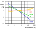 Idealized curves of different class 1 ceramic capacitors
 -
 representation of the tolerance range of temperature coefficient α


Class 2 ceramic capacitors
[edit]
Class 2 ceramic capacitors have a dielectric with a high permittivity and therefore a better volumetric efficiency than class 1 capacitors, but lower accuracy and stability. The ceramic dielectric is characterized by a nonlinear change of capacitance over the temperature range. The capacitance value also depends on the applied voltage. They are suitable for bypass, coupling and decoupling applications or for frequency discriminating circuits where low losses and high stability of capacitance are less important. They typically exhibit microphony.
Class 2 capacitors are made of ferroelectric materials such as barium titanate (BaTiO
3)[13] and suitable additives such as aluminium silicate, magnesium silicate and aluminium oxide.[14] These ceramics have very high permittivity (200 to 14,000), allowing an extreme electric field and therefore capacitance within relatively small packages — class 2 capacitors are significantly smaller than comparable class 1 capacitors. However, the permittivity is nonlinear with respect to field strength, meaning the capacitance varies significantly as the voltage across the terminals increases. Class 2 capacitors also exhibit poor temperature stability and age over time.[11]
Due to these traits, class 2 capacitors are typically used in applications where only a minimum value of capacitance (as opposed to an accurate value) is required, such as the buffering/filtering of inputs and outputs of power supplies, and the coupling of electric signals.
Class 2 capacitors are labeled according to the change in capacitance over the temperature range. The most widely used classification is based on the EIA RS-198 standard and uses a three-digit code. The first character, a letter, denotes the coldest operating temperature; the second character, a numeral, denotes the hottest temperature; and the third character, another letter, denotes the maximum allowed capacitance change over the capacitor's entire specified temperature range:
| Letter code low temperature |
Number code upper temperature |
Letter code change of capacitance over the temperature range |
|---|---|---|
| X = −55 °C (−67 °F) | 4 = +65 °C (+149 °F) | P = ±10% |
| Y = −30 °C (−22 °F) | 5 = +85 °C (+185 °F) | R = ±15% |
| Z = +10 °C (+50 °F) | 6 = +105 °C (+221 °F) | L = ±15%, +15/-40% above 125 °C[15] |
| 7 = +125 °C (+257 °F) | S = ±22% | |
| 8 = +150 °C (+302 °F) | T = +22/−33% | |
| 9 = +200 °C (+392 °F) | U = +22/−56% | |
| V = +22/−82% |
For instance, a Z5U capacitor will operate from +10 °C to +85 °C with a capacitance change of at most +22% to −56%. An X7R capacitor will operate from −55 °C to +125 °C with a capacitance change of at most ±15%.
Some commonly used class 2 ceramic capacitor materials are listed below:
- X8R (−55/+150, ΔC/C0 = ±15%),
- X7R (−55/+125 °C, ΔC/C0 = ±15%),
- X6R (−55/+105 °C, ΔC/C0 = ±15%),
- X5R (−55/+85 °C, ΔC/C0 = ±15%),
- X7S (−55/+125, ΔC/C0 = ±22%),
- Z5U (+10/+85 °C, ΔC/C0 = +22/−56%),
- Y5V (−30/+85 °C, ΔC/C0 = +22/−82%),
The IEC/EN 60384 -9/22 standard uses another two-digit-code.
| Code for capacitance change | Max. capacitance change ΔC/C0 at U = 0 |
Max. capacitance change ΔC/C0 at U = UN |
Code for temperature range | Temperature range |
|---|---|---|---|---|
| 2B | ±10% | +10/−15% | 1 | −55 … +125 °C |
| 2C | ±20% | +20/−30% | 2 | −55 … +85 °C |
| 2D | +20/−30% | +20/−40% | 3 | −40 … +85 °C |
| 2E | +22/−56% | +22/−70% | 4 | −25 … +85 °C |
| 2F | +30/−80% | +30/−90% | 5 | (−10 … +70) °C |
| 2R | ±15% | − | 6 | +10 … +85 °C |
| 2X | ±15% | +15/−25% | – | – |
In most cases it is possible to translate the EIA code into the IEC/EN code. Slight translation errors occur, but normally are tolerable.
- X7R correlates with 2X1
- Z5U correlates with 2E6
- Y5V similar to 2F4, aberration: ΔC/C0 = +30/−80% instead of +30/−82%
- X7S similar to 2C1, aberration: ΔC/C0 = ±20% instead of ±22%
- X8R no IEC/EN code available
Because class 2 ceramic capacitors have lower capacitance accuracy and stability, they require higher tolerance.
For military types the class 2 dielectrics specify temperature characteristic (TC) but not temperature-voltage characteristic (TVC). Similar to X7R, military type BX cannot vary more than 15% over temperature, and in addition, must remain within +15%/-25 % at maximum rated voltage. Type BR has a TVC limit of +15%/-40%.
Class 3 ceramic capacitors
[edit]Class 3 barrier layer or semiconductive ceramic capacitors have very high permittivity, up to 50,000 and therefore a better volumetric efficiency than class 2 capacitors. However, these capacitors have worse electrical characteristics, including lower accuracy and stability. The dielectric is characterized by very high nonlinear change of capacitance over the temperature range. The capacitance value additionally depends on the voltage applied. As well, they have very high losses and age over time.
Barrier layer ceramic capacitors are made of doped ferroelectric materials such as barium titanate (BaTiO
3). As this ceramic technology improved in the mid-1980s, barrier layer capacitors became available in values of up to 100 μF, and at that time it seemed that they could substitute for smaller electrolytic capacitors.

Because it is not possible to build multilayer capacitors with this material, only leaded single layer types are offered in the market. [16] [17]
Due to advancements in multilayer ceramic capacitors enabling superior performance in a smaller package, barrier layer capacitors as a technology are now considered obsolete and no longer standardized by the IEC.
Construction and styles
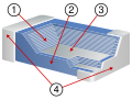
[edit]- Basic structure of ceramic capacitors
-
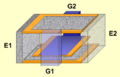
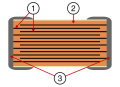 Construction of a multilayer ceramic chip capacitor (MLCC), 1 = Metallic electrodes, 2 = Dielectric ceramic, 3 = Connecting terminals
 -
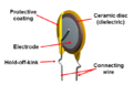 Construction of a ceramic disc capacitor


Ceramic capacitors are composed of a mixture of finely ground granules of paraelectric or ferroelectric materials, appropriately mixed with other materials to achieve the desired characteristics. From these powder mixtures, the ceramic is sintered at high temperatures. The ceramic forms the dielectric and serves as a carrier for the metallic electrodes. The minimum thickness of the dielectric layer, which today (2013) for low voltage capacitors is in the size range of 0.5 micrometers[3] is limited downwards by the grain size of the ceramic powder. The thickness of the dielectric for capacitors with higher voltages is determined by the dielectric strength of the desired capacitor.
The electrodes of the capacitor are deposited on the ceramic layer by metallization. For MLCCs alternating metallized ceramic layers are stacked one above the other. The outstanding metallization of the electrodes at both sides of the body are connected with the contacting terminal. A lacquer or ceramic coating protects the capacitor against moisture and other ambient influences.
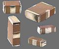
Ceramic capacitors come in various shapes and styles. Some of the most common are:
- Multilayer ceramic chip capacitor (MLCC), rectangular block, for surface mounting
- Ceramic disc capacitor, single layer disc, resin coated, with through-hole leads
- Feedthrough ceramic capacitor, used for bypass purposes in high-frequency circuits. Tube shape, inner metallization contacted with a lead, outer metallization for soldering
- Ceramic power capacitors, larger ceramic bodies in different shapes for high voltage applications
- Some different styles of ceramic capacitors for use in electronic equipment
-
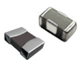 Multilayer ceramic chip capacitor (MLCC)
 -
 Ceramic disc capacitor (single layer)
 -
 Feedthrough ceramic capacitor
 -
 High voltage ceramic power capacitor


Multi-layer ceramic capacitors (MLCC)
[edit]Manufacturing
[edit]- Multi-layer ceramic chip capacitors
-
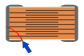
 Detailed construction of a multilayer ceramic chip capacitor (MLCC).
- Ceramic dielectric
- Ceramic or lacquered coating
- Metallized electrode
- Connecting terminals
-
 Samples of multilayer ceramic chip capacitors


An MLCC can be thought of as consisting of many single-layer capacitors stacked together into a single package. The starting material for all MLCC chips is a mixture of finely ground granules of paraelectric or ferroelectric raw materials, modified by accurately determined additives.[18][19] The composition of the mixture and the size of the powder particles, as small as 10 nm, reflect the manufacturer's expertise.
A thin ceramic foil is cast from a suspension of the powder with a suitable binder. Rolls of foil are cut into equal-sized sheets, which are screen printed with a metal paste layer, which will become the electrodes. In an automated process, these sheets are stacked in the required number of layers and solidified by pressure. Besides the relative permittivity, the size and number of layers determines the later capacitance value. The electrodes are stacked in an alternating arrangement slightly offset from the adjoining layers so that they each can later be connected on the offset side, one left, one right. The layered stack is pressed and then cut into individual components. High mechanical precision is required, for example, to produce a 500 or more layer stack of size "0201" (0.5 mm × 0.3 mm).
After cutting, the binder is burnt out of the stack. This is followed by sintering at temperatures between 1,200 and 1,450 °C (2,190 and 2,640 °F), producing the final, mainly crystalline, structure. This burning process creates the desired dielectric properties. Burning is followed by cleaning and then metallization of both end surfaces. Through the metallization, the ends and the inner electrodes are connected in parallel and the capacitor gets its terminals. Finally, each capacitor is electrically tested to ensure functionality and adequate performance, and packaged in a tape reel.

Miniaturizing
[edit]The capacitance formula (C) of a MLCC capacitor is based on the formula for a plate capacitor enhanced with the number of layers:
where ε stands for dielectric permittivity; A for electrode surface area; n for the number of layers; and d for the distance between the electrodes.


A thinner dielectric or a larger electrode area each increase the capacitance value, as will a dielectric material of higher permittivity.
With the progressive miniaturization of digital electronics in recent decades, the components on the periphery of the integrated logic circuits have been scaled down as well. Shrinking an MLCC involves reducing the dielectric thickness and increasing the number of layers. Both options require huge efforts and are connected with a lot of expertise.
In 1995 the minimum thickness of the dielectric was 4 μm. By 2005 some manufacturers produced MLCC chips with layer thicknesses of 1 μm. As of 2010[update], the minimum thickness is about 0.5 μm.[1] The field strength in the dielectric increased to 35 V/μm.[20]
The size reduction of these capacitors is achieved reducing powder grain size, the assumption to make the ceramic layers thinner. In addition, the manufacturing process became more precisely controlled, so that more and more layers can be stacked.
Between 1995 and 2005, the capacitance of a Y5V MLCC capacitor of size 1206 was increased from 4.7 μF to 100 μF.[21] Meanwhile, (2013) a lot of producers can deliver class 2 MLCC capacitors with a capacitance value of 100 μF in the chip-size 0805.[22]
MLCC case sizes
[edit]MLCCs don't have leads, and as a result they are usually smaller than their counterparts with leads. They don't require through-hole access in a PCB to mount and are designed to be handled by machines rather than by humans. As a result, surface-mount components like MLCCs are typically cheaper.
MLCCs are manufactured in standardized shapes and sizes for comparable handling. Because the early standardization was dominated by American EIA standards the dimensions of the MLCC chips were standardized by EIA in units of inches. A rectangular chip with the dimensions of 0.06-inch length and 0.03-inch width is coded as "0603". This code is international and in common use. JEDEC (IEC/EN), devised a second, metric code. The EIA code and the metric equivalent of the common sizes of multilayer ceramic chip capacitors, and the dimensions in mm are shown in the following table. Missing from the table is the measure of the height "H". This is generally not listed, because the height of MLCC chips depends on the number of layers and thus on the capacitance. Normally, however, the height H does not exceed the width W.
| Drawing | EIA inch code |
Dimensions L × W inch × inch |
IEC/EN metric code |
Dimensions L × W mm × mm |
EIA inch code |
Dimensions LxW inch × inch |
IEC/EN metric code |
Dimensions L × W mm × mm | |
|---|---|---|---|---|---|---|---|---|---|
 |
01005 | 0.016 × 0.0079 | 0402 | 0.4 × 0.2 | 1806 | 0.18 × 0.063 | 4516 | 4.5 × 1.6 | |
| 015015 | 0.016 × 0.016 | 0404 | 0.4 × 0.4 | 1808 | 0.18 × 0.079 | 4520 | 4.5 × 2.0 | ||
| 0201 | 0.024 × 0.012 | 0603 | 0.6 × 0.3 | 1812 | 0.18 × 0.13 | 4532 | 4.5 × 3.2 | ||
| 0202 | 0.02 × 0.02 | 0505 | 0.5 × 0.5 | 1825 | 0.18 × 0.25 | 4564 | 4.5 × 6.4 | ||
| 0302 | 0.03 × 0.02 | 0805 | 0.8 × 0.5 | 2010 | 0.20 × 0.098 | 5025 | 5.0 × 2.5 | ||
| 0303 | 0.03 × 0.03 | 0808 | 0.8 × 0.8 | 2020 | 0.20 × 0.20 | 5050 | 5.08 × 5.08 | ||
| 0504 | 0.05 × 0.04 | 1310 | 1.3 × 1.0 | 2220 | 0.225 × 0.197 | 5750 | 5.7 × 5.0 | ||
| 0402 | 0.039 × 0.020 | 1005 | 1.0 × 0.5 | 2225 | 0.225 × 0.25 | 5664/5764 | 5.7 × 6.4 | ||
| 0603 | 0.063 × 0.031 | 1608 | 1.6 × 0.8 | 2512 | 0.25 × 0.13 | 6432 | 6.4 × 3.2 | ||
| 0805 | 0.079 × 0.049 | 2012 | 2.0 × 1.25 | 2520 | 0.25 × 0.197 | 6450 | 6.4 × 5.0 | ||
| 1008 | 0.098 × 0.079 | 2520 | 2.5 × 2.0 | 2920 | 0.29 × 0.197 | 7450 | 7.4 × 5.0 | ||
| 1111 | 0.11 × 0.11 | 2828 | 2.8 × 2.8 | 3333 | 0.33 × 0.33 | 8484 | 8.38 × 8.38 | ||
| 1206 | 0.126 × 0.063 | 3216 | 3.2 × 1.6 | 3640 | 0.36 × 0.40 | 9210 | 9.2 × 10.16 | ||
| 1210 | 0.126 × 0.10 | 3225 | 3.2 × 2.5 | 4040 | 0.4 × 0.4 | 100100 | 10.2 × 10.2 | ||
| 1410 | 0.14 × 0.10 | 3625 | 3.6 × 2.5 | 5550 | 0.55 × 0.5 | 140127 | 14.0 × 12.7 | ||
| 1515 | 0.15 × 0.15 | 3838 | 3.81 × 3.81 | 8060 | 0.8 × 0.6 | 203153 | 20.3 × 15.3 |
NME and BME metallization
[edit]- Influence of the metallization on the voltage dependence of X7R ceramic multilayer chip capacitors
-
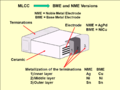 Structure of the electrodes and the NME respectively BME metallization of the terminals of MLCC cchips
 -
 Influence of the NME respectively BME metallization for class 2 X7R MLCC chips on the voltage dependence of capacitance.


Originally, MLCC electrodes were constructed out of noble metals such as silver and palladium which can withstand high sintering temperatures of 1,200 to 1,400 °C (2,190 to 2,550 °F) without readily oxidizing. These noble metal electrode (NME) capacitors offered very good electrical properties.
However, a surge in prices of noble metals in the late 1990s greatly increased manufacturing costs; these pressures resulted in the development of capacitors that used cheaper metals like copper and nickel.[23] These base metal electrode (BME) capacitors possessed poorer electrical characteristics; exhibiting greater shrinkage of capacitance at higher voltages and increased loss factor.
The disadvantages of BME were deemed acceptable for class 2 capacitors, which are primarily used in accuracy-insensitive, low-cost applications such as power supplies. NME still sees use in class 1 capacitors where conformance to specifications are critical and cost is less of a concern.
MLCC capacitance ranges
[edit]
Capacitance of MLCC chips depends on the dielectric, the size and the required voltage (rated voltage). Capacitance values start at about 1pF. The maximum capacitance value is determined by the production technique. For X7R that is 47 μF, for Y5V: 100 μF.
The picture right shows the maximum capacitance for class 1 and class 2 multilayer ceramic chip capacitors. The following two tables, for ceramics NP0/C0G and X7R each, list for each common case size the maximum available capacitance value and rated voltage of the leading manufacturers Murata, TDK, KEMET, AVX. (Status April 2017)
| Rated- voltage |
Case size, EIA Code | ||||||||
|---|---|---|---|---|---|---|---|---|---|
| 01005 | 0201 | 0402 | 0603 | 0805 | 1206 | 1210 | 1812 | 2220 | |
| Dimensions in mm | |||||||||
| 0.4×0.2 | 0.6×0.3 | 1.0×0.5 | 1.6×0.8 | 2.0×1.25 | 3.2×1.6 | 3.2×2.5 | 4.5×3.2 | 5.7×5.0 | |
| Max. capacitance | |||||||||
| 6.3 V | 220 pF | – | – | 33 nF | – | – | – | – | – |
| 10 V | 220 pF | – | 4.7 nF | 33 nF | 100 nF | 100 nF | 220 nF | – | – |
| 16 V | 220 pF | – | 2.2 nF | 15 nF | 47 nF | 120 nF | 220 nF | – | – |
| 25 V | 220 pF | 1.0 nF | 2.2 nF | 47 nF | 47 nF | 120 nF | 220 nF | – | – |
| 50 V | 100 pF | 220 pF | 1.5 nF | 10 nF | 47 nF | 100 nF | 150 nF | 220 nF | 470 nF |
| 100 V | – | 100 pF | 1.0 nF | 4.7 nF | 22 nF | 100 nF | 100 nF | 150 nF | 330 nF |
| 250 V | – | – | 330 pF | 2.2 nF | 8.2 nF | 22 nF | 47 nF | 100 nF | – |
| 500 V | – | – | – | – | 820 pF | 4.7 nF | 10 nF | 22 nF | 47 nF |
| 630 V | – | – | – | – | 1.2 nF | 4.7 nF | 15 nF | 22 nF | 47 nF |
| 1000 V | – | – | – | – | 270 pF | 1.0 nF | 2.7 nF | 5.6 nF | 12 nF |
| 2000 V | – | – | – | – | – | 270 pf | 680 pF | 1.5 nF | 3.9 nF |
| 3000 V | – | – | – | – | – | – | – | 390 pF | 1.0 nF |
| Rated- voltage |
Case size, EIA Code | ||||||||
|---|---|---|---|---|---|---|---|---|---|
| 01005 | 0201 | 0402 | 0603 | 0805 | 1206 | 1210 | 1812 | 2220 | |
| Dimensions in mm | |||||||||
| 0.4×0.2 | 0.6×0.3 | 1.0×0.5 | 1.6×0.8 | 2.0×1.25 | 3.2×1.6 | 3.2×2.5 | 4.5×3.2 | 5.7×5.0 | |
| Max. capacitance | |||||||||
| 4 V | – | – | 2.2 μF | 22 μF | 22 μF | 100 μF | 100 μF | – | – |
| 6.3 V | – | 0.1 μF | 2.2 μF | 10 μF | 22 μF | 47 μF | 100 μF | – | – |
| 10 V | 1.0 nF | 0.1 μF | 2.2 .μF | 10 μF | 22 μF | 22 μF | 47 μF | – | – |
| 16 V | 1.0 nF | 0.1 μF | 2.2 μF | 4.7 μF | 10 μF | 22 μF | 22 μF | – | – |
| 25 V | – | 10 nF | 0.1 μF | 2.2 μF | 10 μF | 10 μF | 22 μF | – | 22 μF |
| 50 V | – | 1.5 nF | 0.1 μF | 0.47 μF | 4.7 μF | 4.7 μF | 10 μF | – | 10 μF |
| 100 V | – | – | 4.7 nF | 0.1 μF | 0.1 μF | 4.7 μF | 10 μF | 3.3 μF | 10 μF |
| 200 V | – | – | – | 10 nF | 56 nF | 0.15 μF | 0.22 μF | 1.0 μF | 1.0 μF |
| 250 V | – | – | – | 2.2 nF | 22 nF | 0.1 μF | 0.22 μF | 0.47 μF | 1.0 μF |
| 500 V | – | – | – | 3.9 nF | 22 nF | 68 nF | 0.1 μF | 0.22 μF | 0.47 μF |
| 630 V | – | – | – | 1.5 nF | 12 nF | 33 nF | 0.1 μF | 0.15 μF | 0.33 μF |
| 1000 V | – | – | – | 1.0 nF | 4.7 nF | 22 nF | 68 nF | 0.1 μF | 0.12 μF |
| 2000 V | – | – | – | – | – | 2.2 nF | 6.8 nF | 10 nF | 22 nF |
| 3000 V | – | – | – | – | – | – | – | 1.2 nF | 15 nF |
Low-ESL styles
[edit]- Comparison of different MLCC designs
-
 Standard MLCC chip design
 -
 Low-ESL design of an MLCC chip
 -
 MLCC chip array


In the region of its resonance frequency, a capacitor has the best decoupling properties for noise or electromagnetic interference. The resonance frequency of a capacitor is determined by the inductance of the component. The inductive parts of a capacitor are summarized in the equivalent series inductance, or ESL. (Note that L is the electrical symbol for inductance.) The smaller the inductance, the higher the resonance frequency.
Because, especially in digital signal processing, switching frequencies have continued to rise, the demand for high frequency decoupling or filter capacitors increases. With a simple design change the ESL of an MLCC chip can be reduced. Therefore, the stacked electrodes are connected on the longitudinal side with the connecting terminations. This reduces the distance that the charge carriers flow over the electrodes, which reduces inductance of the component.[24]
For example, an 0.1 μF X7R MLCC in a 0805 package resonates at 16 MHz. The same capacitor with leads on its long sides (i.e. an 0508) has a resonance frequency of 22 MHz.
Another possibility is to form the device as an array of capacitors. Here, several individual capacitors are built in a common housing. Connecting them in parallel, the resulting ESL as well as ESR values of the components are reduced.
X2Y decoupling capacitor
[edit]- X2Y decoupling capacitor
-
 X2Y decoupling capacitors with different case sizes
 -
 Inner construction of a X2Y capacitor
 -
 Circuit diagram of a X2Y capacitor in a decoupling circuit


A standard multi-layer ceramic capacitor has many opposing electrode layers stacked inside connected with two outer terminations. The X2Y ceramic chip capacitor however is a 4 terminal chip device. It is constructed like a standard two-terminal MLCC out of the stacked ceramic layers with an additional third set of shield electrodes incorporated in the chip. These shield electrodes surround each existing electrode within the stack of the capacitor plates and are low ohmic contacted with two additional side terminations across to the capacitor terminations. The X2Y construction results in a three-node capacitive circuit that provides simultaneous line-to-line and line-to-ground filtering.[25][26][27]
Capable of replacing 2 or more conventional devices, the X2Y ceramic capacitors are ideal for high frequency filtering or noise suppression of supply voltages in digital circuits, and can prove invaluable in meeting stringent EMC demands in dc motors, in automotive, audio, sensor and other applications.[28][29]
The X2Y footprint results in lower mounted inductance.[30] This is particularly of interest for use in high-speed digital circuits with clock rates of several 100 MHz and upwards. There the decoupling of the individual supply voltages on the circuit board is difficult to realize due to parasitic inductances of the supply lines. A standard solution with conventional ceramic capacitors requires the parallel use of many conventional MLCC chips with different capacitance values. Here X2Y capacitors are able to replace up to five equal-sized ceramic capacitors on the PCB.[31] However, this particular type of ceramic capacitor is patented, so these components are still comparatively expensive.
An alternative to X2Y capacitors may be a three-terminal capacitor.[32]
Mechanical susceptibility
[edit]Ceramics are brittle, and MLCC chips surface-mount soldered to a circuit board are often vulnerable to cracking from thermal expansion or mechanical stresses like depanelization, more so than leaded through-hole components. The cracks can come from automated machine assembly line, or from high current in the circuit.
Vibration and shock forces on the circuit board are more or less transmitted undampened to the MLCC and its solder joints; excessive force may cause the capacitor to crack (flex crack). Excess solder in the joints are undesirable as they may magnify the forces that the capacitor is subject to.[33][34]
- MLCC chips – correct mounted – cracked chip – substrate bending test
-
 Correct mounted and soldered MLCC chip on a PCB
 -
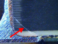 Micrograph of broken ceramic in a MLCC chip
 -
 Simplified figure of a bending test for soldered MLCC


The capability of MLCC chips to withstand mechanical stress is tested by a so-called substrate bending test, where a PCB with a soldered MLCC is bent by a punch by 1 to 3 mm. Failure occurs if the MLCC becomes a short-circuit or significantly changes in capacitance.
Bending strengths of MLCC chips differ by the ceramic material, the size of the chip, and the physical construction of the capacitors. Without special mitigation, NP0/C0G class 1 ceramic MLCC chips reach a typical bending strength of 2 mm while larger types of X7R, Y5V class 2 ceramic chips achieved only a bending strength of approximately 1 mm. Smaller chips, such as the size of 0402, reached in all types of ceramics larger bending strength values.
With special design features, particularly at the electrodes and terminations, the bending strength can be improved. For example, an internal short circuit arises by the contact of two electrodes with opposite polarity, which will be produced at the break of the ceramic in the region of the terminations. This can be prevented when the overlap surfaces of the electrodes are reduced. This is achieved e.g. by an "Open Mode Design" (OMD). Here a break in the region of the terminations only reduce the capacitance value a little bit (AVX, KEMET).
- Different MLCC constructions to minimize mechanical stress
-
 Standard MLCC chip, short circuit possible if ceramic breaks due to mechanical stress
 -
 „Open-Mode-Design" MLCC chip, a break only reduces the capacitance value
 -
 "Floating-Electrode-Design"-MLCC, a break only reduces the capacitance value
 -
!["Flex-Termination" - MLCC chips, a flexible contact layer prevents breaking of the ceramic.[35]](//upload.wikimedia.org/wikipedia/commons/thumb/f/fc/MLCC-FlexTerm-Crack.svg/120px-MLCC-FlexTerm-Crack.svg.png) "Flex-Termination" - MLCC chips, a flexible contact layer prevents breaking of the ceramic.[35]
"Flex-Termination" - MLCC chips, a flexible contact layer prevents breaking of the ceramic.[35]


!["Flex-Termination" - MLCC chips, a flexible contact layer prevents breaking of the ceramic.[35]](https://en.wikipedia.org/wiki/File:MLCC-FlexTerm-Crack.svg)
With a similar construction called "Floating Electrode Design" (FED) or "Multi-layer Serial Capacitors" (MLSC), also, only capacitance reduction results if parts of the capacitor body break. This construction works with floating electrodes without any conductive connection to the termination. A break doesn't lead to a short, only to capacitance reduction. However, both structures lead to larger designs with respect to a standard MLCC version with the same capacitance value.
The same volume with respect to standard MLCCs is achieved by the introduction of a flexible intermediate layer of a conductive polymer between the electrodes and the termination called "Flexible Terminations" (FT-Cap) or "Soft Terminations". In this construction, the rigid metallic soldering connection can move against the flexible polymer layer, and thus can absorb the bending forces, without resulting in a break in the ceramic.[36] Some automotive capacitors are specified to adhere to AEC-Q200 and/or VW 80808.
RFI/EMI suppression with X- and Y capacitors
[edit]Suppression capacitors are effective interference reduction components because their electrical impedance decreases with increasing frequency, such that at higher frequencies they appear as short circuits to high-frequency electrical noise and transients between the lines, or to ground. They therefore prevent equipment and machinery (including motors, inverters, and electronic ballasts, as well as solid-state relay snubbers and spark quenchers) from sending and receiving electromagnetic and radio frequency interference as well as transients in across-the-line (X capacitors) and line-to-ground (Y capacitors) connections. X capacitors effectively absorb symmetrical, balanced, or differential interference. Y capacitors are connected in a line bypass between a line phase and a point of zero potential, to absorb asymmetrical, unbalanced, or common-mode interference.[37][38][39]
- RFI/EMI suppression with X- and Y-capacitors for equipment without and with additional safety insulation
-
 Appliance Class I capacitor connection
 -
 Appliance Class II capacitor connection


EMI/RFI suppression capacitors are designed so that any remaining interference or electrical noise does not exceed the limits of EMC directive EN 50081.[40] Suppression components are connected directly to mains voltage for 10 to 20 years or more and are therefore exposed to potentially damaging overvoltages and transients. For this reason, suppression capacitors must comply with the safety and non-flammability requirements of international safety standards such as
- Europe: EN 60384-14,
- USA: UL 1414, UL 1283
- Canada: CSA C22.2, No.1, CSA C22.2, No.8
- China: CQC (GB/T 14472-1998)
RFI capacitors that fulfill all specified requirements are imprinted with the certification mark of various national safety standards agencies. For power line applications, special requirements are placed on the non-flammability of the coating and the epoxy resin impregnating or coating the capacitor body. To receive safety approvals, X and Y powerline-rated capacitors are destructively tested to the point of failure. Even when exposed to large overvoltage surges, these safety-rated capacitors must fail in a fail-safe manner that does not endanger personnel or property.
As of 2012[update] most ceramic capacitors used for EMI/RFI suppression were leaded ones for through-hole mounting on a PCB,[41][42] the surface-mount technique is becoming more and more important. For this reason, in recent years a lot of MLCC chips for EMI/RFI suppression from different manufacturers have received approvals and fulfill all requirements given in the applicable standards.[41][43][44][45][46]
Ceramic power capacitors
[edit]- Different styles of ceramic capacitors for power electronic
-
Doorknob style high voltage ceramic capacitor
-
 Disc style power ceramic capacitor
 -
 Tubular or pot style power ceramic capacitor


Although the materials used for large power ceramic capacitors mostly are very similar to those used for smaller ones, ceramic capacitors with high to very high power or voltage ratings for applications in power systems, transmitters and electrical installations are often classified separately, for historical reasons. The standardization of ceramic capacitors for lower power is oriented toward electrical and mechanical parameters as components for use in electronic equipment. The standardization of power capacitors, contrary to that, is strongly focused on protecting personnel and equipment, given by the local regulating authority.

As modern electronic equipment gained the ability to handle power levels that were previously the exclusive domain of "electrical power" components, the distinction between the "electronic" and "electrical" power ratings has become less distinct. In the past, the boundary between these two families was approximately at a reactive power of 200 volt-amps, but modern power electronics can handle increasing amounts of power.
Power ceramic capacitors are mostly specified for much higher than 200 volt-amps. The great plasticity of ceramic raw material and the high dielectric strength of ceramics deliver solutions for many applications and are the reasons for the enormous diversity of styles within the family of power ceramic capacitors. These power capacitors have been on the market for decades. They are produced according to the requirements as class 1 power ceramic capacitors with high stability and low losses or class 2 power ceramic capacitors with high volumetric efficiency.
Class 1 power ceramic capacitors are used for resonant circuit application in transmitter stations. Class 2 power ceramic capacitors are used for circuit breakers, for power distribution lines, for high voltage power supplies in laser-applications, for induction furnaces and in voltage-doubling circuits. Power ceramic capacitors can be supplied with high rated voltages in the range of 2 kV up to 100 kV.[47]
The dimensions of these power ceramic capacitors can be very large. At high power applications the losses of these capacitors can generate a lot of heat. For this reason some special styles of power ceramic capacitors have pipes for water-cooling.
Electrical characteristics
[edit]Series-equivalent circuit
[edit]
All electrical characteristics of ceramic capacitors can be defined and specified by a series equivalent circuit composed out of an idealized capacitance and additional electrical components, which model all losses and inductive parameters of a capacitor. In this series-equivalent circuit the electrical characteristics of a capacitors is defined by
- C, the capacitance of the capacitor,
- Rinsul, the insulation resistance of the dielectric, not to be confused with the insulation of the housing
- RESR, the equivalent series resistance, which summarizes all ohmic losses of the capacitor, usually abbreviated as "ESR".
- LESL, the equivalent series inductance, which is the effective self-inductance of the capacitor, usually abbreviated as "ESL".
The use of a series equivalent circuit instead of a parallel equivalent circuit is defined in IEC/EN 60384-1.
Capacitance standard values and tolerances
[edit]The "rated capacitance" CR or "nominal capacitance" CN is the value for which the capacitor has been designed. The actual capacitance depends on the measuring frequency and the ambient temperature. Standardized conditions for capacitors are a low-voltage AC measuring method at a temperature of 20 °C with frequencies of
- Class 1 ceramic capacitors
- CR ≤ 100 pF at 1 MHz, measuring voltage 5 V
- CR > 100 pF at 1 kHz, measuring voltage 5 V
- Class 2 ceramic capacitors
- CR ≤ 100 pF at 1 MHz, measuring voltage 1 V
- 100 pF < CR ≤ 10 μF at 1 kHz, measuring voltage 1 V
- CR > 10 μF at 100/120 Hz, measuring voltage 0.5 V
Capacitors are available in different, geometrically increasing preferred values as specified in the E series standards specified in IEC/EN 60063. According to the number of values per decade, these were called the E3, E6, E12, E24, etc. series. The units used to specify capacitor values includes everything from picofarad (pF), nanofarad (nF), microfarad (μF) and farad (F).
The percentage of allowed deviation of the capacitance from the rated value is called capacitance tolerance. The actual capacitance value must be within the tolerance limits, or the capacitor is out of specification. For abbreviated marking in tight spaces, a letter code for each tolerance is specified in IEC/EN 60062.
| E series | Tolerance | |||
|---|---|---|---|---|
| CR > 10 pF | Letter code | CR < 10 pF | Letter code | |
| E96 | 1% | F | 0.1 pF | B |
| E48 | 2% | G | 0.25 pF | C |
| E24 | 5% | J | 0.5 pF | D |
| E12 | 10% | K | 1 pF | F |
| E6 | 20% | M | 2 pF | G |
| E3 | −20/+50% | S | - | - |
| −20/+80% | Z | - | - | |
The required capacitance tolerance is determined by the particular application. The narrow tolerances of E24 to E96 will be used for high-quality class 1 capacitors in circuits such as precision oscillators and timers. For applications such as non-critical filtering or coupling circuits, for class 2 capacitors the tolerance series E12 down to E3 are sufficient.
Temperature dependence of capacitance
[edit]Capacitance of ceramic capacitors varies with temperature. The different dielectrics of the many capacitor types show great differences in temperature dependence. The temperature coefficient is expressed in parts per million (ppm) per degree Celsius for class 1 ceramic capacitors or in percent (%) over the total temperature range for class 2 capacitors.
| Type of capacitor, dielectric material |
Temperature coefficient C/C0 |
Application temperature range |
|---|---|---|
| Ceramic capacitors class 1 paraelectric NP0 |
±30 ppm/K (±0.5%) | −55…+125 °C |
| Ceramic capacitors class 2, ferroelectric X7R |
±15% | −55…+125 °C |
| Ceramic capacitors class 2, ferroelectric Y5V |
+22% / −82% | −30…+85 °C |
Frequency dependence of capacitance
[edit]
Most discrete capacitor types have greater or smaller capacitance changes with increasing frequencies. The dielectric strength of class 2 ceramic and plastic film diminishes with rising frequency. Therefore, their capacitance value decreases with increasing frequency. This phenomenon is related to the dielectric relaxation in which the time constant of the electrical dipoles is the reason for the frequency dependence of permittivity. The graph on the right hand side shows typical frequency behavior for class 2 vs class 1 capacitors.
Voltage dependence of capacitance
[edit]
Capacitance of ceramic capacitors may also change with applied voltage. This effect is more prevalent in class 2 ceramic capacitors. The ferroelectric material depends on the applied voltage.[48][49] The higher the applied voltage, the lower the permittivity. Capacitance measured or applied with higher voltage can drop to values of −80% of the value measured with the standardized measuring voltage of 0.5 or 1.0 V. This behavior is a small source of nonlinearity in low-distortion filters and other analog applications. In audio applications this can be the reason for harmonic distortions.
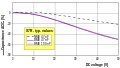
- Voltage dependence of capacitance for some different class 2 ceramic capacitors
-
 Simplified diagram of the change in capacitance as a function of the applied voltage for 25-V capacitors in different kind of ceramic grades
 -
 Simplified diagram of the change in capacitance as a function of applied voltage for X7R ceramics with different rated voltages


The voltage dependence of capacitance in the two diagrams above shows curves from ceramic capacitors with NME metallization. For capacitors with BME metallization the voltage dependence of capacitance increased significantly.[50][51][52][53]
Voltage proof
[edit]For most capacitors, a physically conditioned dielectric strength or a breakdown voltage usually could be specified for each dielectric material and thickness. This is not possible with ceramic capacitors. The breakdown voltage of a ceramic dielectric layer may vary depending on the electrode material and the sintering conditions of the ceramic up to a factor of 10. A high degree of precision and control of process parameters is necessary to keep the scattering of electrical properties for today's very thin ceramic layers within specified limits.
The voltage proof of ceramic capacitors is specified as rated voltage (UR). This is the maximum DC voltage that may be continuously applied to the capacitor up to the upper temperature limit. This guaranteed voltage proof is tested according to the voltages shown in the adjacent table.
Furthermore, in periodic life time tests (endurance tests) the voltage proof of ceramic capacitors is tested with increased test voltage (120 to 150% of UR) to ensure safe construction.
| Style | Rated voltage | Test voltage |
|---|---|---|
| Ceramic- multilayer chip capacitors (MLCC) |
UR ≤ 100 V | 2.5 UR |
| 100 V < UR ≤ 200 V | 1.5 UR + 100 V | |
| 200 V < UR ≤ 500 V | 1.3 UR + 100 V | |
| 500 V < UR | 1.3 UR | |
| Single layer- ceramic capacitors |
UR ≤ 500 V | 2.5 UR |
| UR > 500 V | 1.5 UR + 500 V |
Impedance
[edit]
The frequency dependent AC resistance of a capacitor is called impedance and is a complex ratio of voltage to current in an AC circuit. Impedance extends the concept of Ohm's law to AC circuits, and possesses both magnitude and phase at a particular frequency, unlike resistance, which has only magnitude.

Impedance is a measure of the ability of the capacitor to pass alternating currents. In this sense impedance can be used like Ohms law

to calculate either the peak or the effective value of the current or the voltage.
As shown in the series-equivalent circuit of a capacitor, the real-world component includes an ideal capacitor , an inductance and a resistor .


To calculate the impedance the resistance and then both reactances have to be added geometrically

wherein the capacitive reactance (Capacitance) is

and an inductive reactance (Inductance) is
- .

In the special case of resonance, in which both reactive resistances have the same value (), then the impedance will only be determined by .


Data sheets of ceramic capacitors only specify the impedance magnitude . The typical impedance curve shows that with increasing frequency, impedance decreases, down to a minimum. The lower the impedance, the more easily alternating currents can pass through the capacitor. At the minimum point of the curve, the point of resonance, where XC has the same value as XL, the capacitor exhibits its lowest impedance value. Here only the ohmic ESR determines the impedance. With frequencies above the resonance, impedance increases again due to the ESL.
ESR, dissipation factor, and quality factor
[edit]The summarized losses in ceramic capacitors are ohmic AC losses. DC losses are specified as "leakage current" or "insulating resistance" and are negligible for an AC specification. These AC losses are nonlinear and may depend on frequency, temperature, age, and for some special types, on humidity. The losses result from two physical conditions,
- line losses with internal supply line resistances, the contact resistance of the electrode contact, the line resistance of the electrodes
- the dielectric losses out of the dielectric polarization
The largest share of these losses in larger capacitors is usually the frequency dependent ohmic dielectric losses. Regarding the IEC 60384-1 standard, the ohmic losses of capacitors are measured at the same frequency used to measure capacitance. These are:
- 100 kHz, 1 MHz (preferred) or 10 MHz for ceramic capacitors with CR ≤ 1 nF:
- 1 kHz or 10 kHz for ceramic capacitors with 1 nF < CR ≤ 10 μF
- 50/60 Hz or 100/120 Hz for ceramic capacitors with CR > 10 μF
Results of the summarized resistive losses of a capacitor may be specified either as equivalent series resistance (ESR), as dissipation factor (DF, tan δ), or as quality factor (Q), depending on the application requirements.
Class 2 capacitors are mostly specified with the dissipation factor, tan δ. The dissipation factor is determined as the tangent of the reactance – and the ESR, and can be shown as the angle δ between the imaginary and impedance axes in the above vector diagram, see paragraph "Impedance".


If the inductance is small, the dissipation factor can be approximated as:


Class 1 capacitors with very low losses are specified with a dissipation factor and often with a quality factor (Q). The quality factor is defined as the reciprocal of the dissipation factor.

The Q factor represents the effect of electrical resistance, and characterizes a resonator's bandwidth relative to its center or resonant frequency . A high Q value is a mark of the quality of the resonance for resonant circuits.


In accordance with IEC 60384-8/-21/-9/-22 ceramic capacitors may not exceed the following dissipation factors:
| Temperature coefficient of the ceramic |
Maximum dissipation factor |
|---|---|
| 100 ≥ α > −750 | tan δ ≤ 15 • 10−4 |
| −750 ≥ α > −1500 | tan δ ≤ 20 • 10−4 |
| −1500 ≥ α > −3300 | tan δ ≤ 30 • 10−4 |
| −3300 ≥ α > −5600 | tan δ ≤ 40 • 10−4 |
| ≤ −5600 | tan δ ≤ 50 • 10−4 |
| For capacitance values < 50 pF the dissipation factor may be larger | |
| Rated voltage of the capacitor |
maximum dissipation factor |
|---|---|
| ≥ 10 V | tan δ ≤ 350 • 10−4 |
| For capacitance values < 50 pF the dissipation factor may be larger | |
The ohmic losses of ceramic capacitors are frequency, temperature and voltage dependent. Additionally, class 2 capacitor measurements change because of aging. Different ceramic materials have differing losses over the temperature range and the operating frequency. The changes in class 1 capacitors are in the single-digit range while class 2 capacitors have much higher changes.
HF use, inductance (ESL) and self-resonant frequency
[edit]Electrical resonance occurs in a ceramic capacitor at a particular resonance frequency where the imaginary parts of the capacitor impedance and admittances cancel each other. This frequency where XC is as high as XL is called the self-resonant frequency and can be calculated with:

where ω = 2πf, in which f is the resonance frequency in Hertz, L is the inductance in henries, and C is the capacitance in farads.
The smaller the capacitance C and the inductance L the higher is the resonance frequency. The self-resonant frequency is the lowest frequency at which impedance passes through a minimum. For any AC application the self-resonant frequency is the highest frequency at which a capacitor can be used as a capacitive component. At frequencies above the resonance, the impedance increases again due to ESL: the capacitor becomes an inductor with inductance equal to capacitor's ESL, and resistance equal to ESR at the given frequency.
ESL in industrial capacitors is mainly caused by the leads and internal connections used to connect the plates to the outside world. Larger capacitors tend to higher ESL than small ones, because the distances to the plate are longer and every millimeter increases inductance.
Ceramic capacitors, which are available in the range of very small capacitance values (pF and higher) are already out of their smaller capacitance values suitable for higher frequencies up to several 100 MHz (see formula above). Due to the absence of leads and proximity to the electrodes, MLCC chips have significantly lower parasitic inductance than f. e. leaded types, which makes them suitable for higher frequency applications. A further reduction of parasitic inductance is achieved by contacting the electrodes on the longitudinal side of the chip instead of the lateral side.
Sample self-resonant frequencies for one set of NP0/C0G and one set of X7R ceramic capacitors are:[54]
| 10 pF | 100 pF | 1 nF | 10 nF | 100 nF | 1 μF | |
|---|---|---|---|---|---|---|
| C0G (Class 1) | 1550 MHz | 460 MHz | 160 MHz | 55 MHz | ||
| X7R (Class 2) | 190 MHz | 56 MHz | 22 MHz | 10 MHz |
Note that X7Rs have better frequency response than C0Gs. It makes sense, however, since class 2 capacitors are much smaller than class 1, so they ought to have lower parasitic inductance.
Aging
[edit]
In ferroelectric class 2 ceramic capacitors capacitance decreases over time. This behavior is called "aging". Aging occurs in ferroelectric dielectrics, where domains of polarization in the dielectric contribute to total polarization. Degradation of the polarized domains in the dielectric decreases permittivity over time so that the capacitance of class 2 ceramic capacitors decreases as the component ages.[55] [56]
The aging follows a logarithmic law. This law defines the decrease of capacitance as a percentage for a time decade after the soldering recovery time at a defined temperature, for example, in the period from 1 to 10 hours at 20 °C. As the law is logarithmic, the percentage loss of capacitance will twice between 1 h and 100 h and 3 times between 1 h and 1000 h and so on. So aging is fastest near the beginning, and the capacitance value effectively stabilizes over time.
The rate of aging of class 2 capacitors mainly depends on the materials used. A rule of thumb is, the higher the temperature dependence of the ceramic, the higher the aging percentage. The typical aging of X7R ceramic capacitors is about 2.5% per decade[57] The aging rate of Z5U ceramic capacitors is significantly higher and can be up to 7% per decade.
The aging process of class 2 capacitors may be reversed by heating the component above the Curie point.[2]
Class 1 capacitors do not experience ferroelectric aging like Class 2's. But environmental influences such as higher temperature, high humidity and mechanical stress can, over a longer period of time, lead to a small irreversible decline in capacitance, sometimes also called aging. The change of capacitance for P 100 and N 470 Class 1's is lower than 1%, for capacitors with N 750 to N 1500 ceramics it is ≤ 2%.
Insulation resistance and self-discharge constant
[edit]The resistance of the dielectric is never infinite, leading to some level of DC "leakage current", which contributes to self-discharge. For ceramic capacitors this resistance, placed in parallel with the capacitor in the series-equivalent circuit of capacitors, is called "insulation resistance Rins". The insulation resistance must not be confused with the outer isolation with respect to the environment.
The rate of self-discharge with decreasing capacitor voltage follows the formula

With the stored DC voltage and the self-discharge constant


That means, after capacitor voltage dropped to 37% of the initial value.

The insulation resistance given in the unit MΩ (106 Ohm) as well as the self-discharge constant in seconds is an important parameter for the quality of the dielectric insulation. These time values are important, for example, when a capacitor is used as timing component for relays or for storing a voltage value as in a sample and hold circuits or operational amplifiers.
In accordance with the applicable standards, Class 1 ceramic capacitors have an Rins ≥ 10,000 MΩ for capacitors with CR ≤ 10 nF or τs ≥ 100 s for capacitors with CR > 10 nF. Class 2 ceramic capacitors have an Rins ≥ 4,000 MΩ for capacitors with CR ≤ 25 nF or τs ≥ 100 s for capacitors with CR > 25 nF.
Insulation resistance and thus the self-discharge time rate are temperature dependent and decrease with increasing temperature at about 1 MΩ per 60 °C.
Dielectric absorption (soakage)
[edit]Dielectric absorption is the name given to the effect by which a capacitor, which has been charged for a long time, discharges only incompletely. Although an ideal capacitor remains at zero volts after discharge, real capacitors will develop a small voltage coming from time-delayed dipole discharging, a phenomenon that is also called dielectric relaxation, "soakage" or "battery action".
| Type of capacitor | Dielectric Absorption |
|---|---|
| Class-1 ceramic capacitors, NP0 | 0.3 to 0.6% |
| Class-2 ceramic capacitors, X7R | 2.0 to 2.5% |
In many applications of capacitors dielectric absorption is not a problem but in some applications, such as long-time-constant integrators, sample-and-hold circuits, switched-capacitor analog-to-digital converters and very low-distortion filters, it is important that the capacitor does not recover a residual charge after full discharge, and capacitors with low absorption are specified. The voltage at the terminals generated by dielectric absorption may in some cases possibly cause problems in the function of an electronic circuit or can be a safety risk to personnel. To prevent shocks, most very large capacitors like power capacitors are shipped with shorting wires that are removed before use.[58]
Microphony
[edit]All class 2 ceramic capacitors using ferroelectric ceramics exhibit piezoelectricity, and have a piezoelectric effect called microphonics, microphony or in audio applications squealing.[59] Microphony describes the phenomenon wherein electronic components transform mechanical vibrations into an electrical signal which in many cases is undesired noise.[60] Sensitive electronic preamplifiers generally use class 1 ceramic and film capacitors to avoid this effect.[60]
In the reverse microphonic effect, the varying electric field between the capacitor plates exerts a physical force, moving them as a speaker.[60] High current impulse loads or high ripple currents can generate audible acoustic sound coming from the capacitor, but discharges the capacitor and stresses the dielectric.[61][62][63]
Soldering
[edit]Ceramic capacitors may experience changes to their electrical parameters due to soldering stress. The heat of the solder bath, especially for SMD styles, can cause changes of contact resistance between terminals and electrodes. For ferroelectric class 2 ceramic capacitors, the soldering temperature is above the Curie point. The polarized domains in the dielectric are going back and the aging process of class 2 ceramic capacitors is starting again.[2]
Hence after soldering a recovery time of approximately 24 hours is necessary. After recovery some electrical parameters like capacitance value, ESR, leakage currents are changed irreversibly. The changes are in the lower percentage range depending on the style of capacitor.
Additional information
[edit]Standardization
[edit]The standardization for all electrical, electronic components and related technologies follows the rules given by the International Electrotechnical Commission (IEC),[64] a non-profit, non-governmental international standards organization.[65][66]
The definition of the characteristics and the procedure of the test methods for capacitors for use in electronic equipment are set out in the generic specification:
- IEC 60384-1, Fixed capacitors for use in electronic equipment – Part 1: Generic specification
The tests and requirements to be met by ceramic capacitors for use in electronic equipment for approval as standardized types are set out in the following sectional specifications:
- IEC 60384-8, Fixed capacitors of ceramic dielectric, Class 1
- IEC 60384-9, Fixed capacitors of ceramic dielectric, Class 2
- IEC 60384-21, Fixed surface mount multilayer capacitors of ceramic dielectric, Class 1
- IEC 60384-22, Fixed surface mount multilayer capacitors of ceramic dielectric, Class 2
Tantalum capacitor replacement
[edit]Multilayer ceramic capacitors are increasingly used to replace tantalum and low capacitance aluminium electrolytic capacitors in applications such as bypass or high frequency switched-mode power supplies as their cost, reliability and size becomes competitive. In many applications, their low ESR allows the use of a lower nominal capacitance value.[67][68][69][70][71]
Features and disadvantages of ceramic capacitors
[edit]For features and disadvantages of ceramic capacitors see main article Capacitor types#Comparison of types
Marking
[edit]
Imprinted markings
[edit]If space permits ceramic capacitors, like most other electronic components, have imprinted markings to indicate the manufacturer, the type, their electrical and thermal characteristics and their date of manufacture. In the ideal case, if they are large enough, the capacitor will be marked with:
- manufacturer's name or trademark;
- manufacturer's type designation;
- rated capacitance;
- tolerance on rated capacitance
- rated voltage and nature of supply (AC or DC)
- climatic category or rated temperature;
- year and month (or week) of manufacture;
- certification marks of safety standards (for safety EMI/RFI suppression capacitors)
Smaller capacitors use a shorthand notation, to display all the relevant information in the limited space. The most commonly used format is: XYZ J/K/M VOLTS V, where XYZ represents the capacitance (calculated as XY × 10Z pF), the letters J, K or M indicate the tolerance (±5%, ±10% and ±20% respectively) and VOLTS V represents the working voltage.
Examples
[edit]- A capacitor with the following text on its body: 105K 330V has a capacitance of 10 × 105 pF = 1 μF (K = ±10%) with a working voltage of 330 V.
- A capacitor with the following text: 473M 100V has a capacitance of 47 × 103 pF = 47 nF (M = ±20%) with a working voltage of 100 V.
Capacitance, tolerance and date of manufacture can be identified with a short code according to IEC/EN 60062. Examples of short-marking of the rated capacitance (microfarads):
- μ47 = 0.47 μF
- 4μ7 = 4.7 μF
- 47μ = 47 μF
The date of manufacture is often printed in accordance with international standards.
- Version 1: coding with year/week numeral code, "1208" is "2012, week number 8".
- Version 2: coding with year code/month code,
Year code: "R" = 2003, "S"= 2004, "T" = 2005, "U" = 2006, "V" = 2007, "W" = 2008, "X" = 2009, "A" = 2010, "B" = 2011, "C" = 2012, "D" = 2013 etc.
Month code: "1" to "9" = Jan. to Sept., "O" = October, "N" = November, "D" = December
"X5" is then "2009, May"
For very small capacitors like MLCC chips no marking is possible. Here only the traceability of the manufacturers can ensure the identification of a type.
Colour coding
[edit]The identification of modern capacitors has no detailed color coding.
See also
[edit]References
[edit]- ^ a b c d e Ho, J.; Jow, T. R.; Boggs, S. (2010). "Historical introduction to capacitor technology". IEEE Electrical Insulation Magazine. 26: 20–25. doi:10.1109/MEI.2010.5383924. S2CID 23077215.Download Archived 2016-12-05 at the Wayback Machine
- ^ a b c Waugh, Mark D. "Design solutions for DC bias in multilayer ceramic capacitors" (PDF). Murata. Archived from the original (PDF) on May 13, 2012.
- ^ a b "Murata, Technical Report, Evolving Capacitors". Archived from the original on June 17, 2012.
- ^ "MLCC Shortages and Why They Might Last Longer than Expected". ttiinc.com. Retrieved 2019-10-20.
- ^ Hillard, Henry E. (2001). "Platinum-Group Metals". Metals and minerals: US Geological Survey Minerals Yearbook 2001. 1. U.S. Geological Survey: 59.1 – 59.5. doi:10.3133/mybvl. Retrieved 28 May 2025.
- ^ Kendall, Tom, ed. (1 July 2002). "Platinum 2002". Platinum Metals Review. 46 (3). Johnson Matthey: 116. doi:10.1595/003214002X463116116. ISSN 0268-7305. Retrieved 28 May 2025.
- ^ Hackenberger, W.; Kwon, S.; Alberta, E. "Advanced Multilayer Capacitors Using High Energy Density Antiferroelectric Ceramics" (PDF). TRS Technologies Inc. Archived from the original (PDF) on 2013-09-29.
- ^ "CLASS III –General Purpose High-K Ceramic Disk Capacitors" (PDF). Chroma Technology Co., Ltd. Archived from the original (PDF) on July 20, 2013.
- ^ "Kemet: Ceramic leaded Capacitors F-3101F06/05" (PDF). Archived from the original (PDF) on 2008-10-10.
- ^ Ceramic Ceramic Archived 2008-03-31 at the Wayback Machine
- ^ a b Otto Zinke; Hans Seither (2002), Widerstände, Kondensatoren, Spulen und ihre Werkstoffe (in German) (2. ed.), Berlin: Springer
- ^ W. S. Lee, J. Yang, T. Yang, C. Y. Su, Y. L. Hu, Yageo: In: Passive Components Industry, 2004, page 26ff Ultra High-Q NP0 MLCC with Ag inner Electrode for Telecommunication Application[permanent dead link]
- ^ Chin, Trento (Dec 27, 2023). "A Comparison between Tantalum and Multilayer Ceramic Capacitors". Stanford Advanced Materials. Retrieved Sep 7, 2024.
- ^ Huang, Haitao; Scott, James, eds. (2019). "Chapter 5-Dielectric ceramics and films for electrical energy storage". Ferroelectric Materials for Energy Applications. p. 124. ISBN 978-3-527-34271-6.
- ^ "High Temperature – X8R/X8L Dielectric | AVX".
- ^ "Semiconductive (Barrier Layer Type) Capacitor, Class III : Semi- conductive type". Yellow Stone corp. Archived from the original on August 30, 2012.
- ^ Hitano. "CERAMIC DISC CAPACITORS-(Semi Conductive) CLASS 3 TYPE S, Y5P… Y5V" (PDF).[dead link]
- ^ Kahn, M. "MULTILAYER CERAMIC CAPACITORS–MATERIALS AND MANUFACTURE, TECHNICAL INFORMATION" (PDF). AVX Corporation. Archived from the original (PDF) on July 25, 2012.
- ^ APITech. "Ceramic Capacitors". info.apitech.com. Retrieved 2021-09-13.
- ^ "Intel Voices Concerns Over Quality of High Capacitance Ceramic Chip Capacitors". Archived from the original on 2013-10-12. Retrieved 2012-12-14.
- ^ Tsubota, Shoji. "High-Capacitance Capacitors by Murata Make Smaller Power Supplies" (PDF). Archived from the original (PDF) on November 5, 2012. AEI December 2005
- ^ "Taiyo Yuden Introduces World's First 100 μF EIA 0805 Size Multilayer Ceramic Capacitor" (PDF).
- ^ Nagoshi, Yuki (November 2009). "Wielding Base Metal Yields Cheaper, Stable Class X2 Capacitors". AEI.
- ^ AVX, Low Inductance Capacitors Archived May 16, 2013, at the Wayback Machine
- ^ X2Y Attenuators LLC
- ^ X2Y Technology Summary
- ^ "Syfer, X2Y Technology". Archived from the original on 2012-02-27. Retrieved 2012-12-14.
- ^ Multilayer Ceramic EMI-Filter, Syfer[permanent dead link]
- ^ "X2Y Technology overview Johanson". Archived from the original on 2013-08-31. Retrieved 2013-08-11.
- ^ Decoupling Capacitors, A Designer’s Roadmap to Optimal Decoupling Networks for Integrated Circuits
- ^ X2Y Capacitor Technology
- ^ Three-terminal Capacitor Structure, Murata
- ^ "Avoiding Pad Cratering and Capacitor Cracking webinar | DFR Solutions".
- ^ O’Malley, P.; Wang, D.; Duong, H.; Lai, Anh; Zelle, Z. (May 25, 2011). "Ceramic Capacitor Failures and Lessons Learned" (PDF). Proceedings of the 55th Annual NDIA Fuze Conference. Archived from the original (PDF) on 2012-01-13.
- ^ Staubli, P.; Prymak, J.; Blais, P.; Long, B. (25–28 September 2006). "Improving Flex Capabilities with Modified MLC Chip Capacitors" (PDF). Proceedings of CARTS Europe 2006. Archived from the original (PDF) on 2013-09-29.
- ^ Sloka, Bill; Skamser, Dan; Phillips, Reggie; Hill, Allen; Laps, Mark; Grace, Roy; Prymak, John; Randall, Michael; Tajuddin, Aziz (March 26–29, 2007). "Flexure Robust Capacitors" (PDF). Proceedings from CARTS USA 2007. Archived from the original (PDF) on 2008-07-25. Retrieved 2012-12-27.
- ^ Vishay, General Technical Information, Radio Interference Suppression Capacitors
- ^ Illinois capacitor inc. EMI/RFI Suppression Capacitors
- ^ Capacor, General technical information of (RFI/EMI)Noise suppression capacitors on AC mains Archived 2014-01-04 at the Wayback Machine
- ^ "Electromagnetic Compatibility (EMC) Legislation: Directive 89/336/EC". European Commission. Archived from the original on 2012-07-05. Retrieved 2012-08-02.
- ^ a b Murata, Ceramic Capacitors Certified by safety standard/Compliant with EA&MS Act [1]
- ^ Vishay, Capacitors – Ceramic – RFI Class X/Y Vishay, Capacitors – Ceramic – RFI Class X/Y Archived August 15, 2012, at the Wayback Machine
- ^ Syfer's MLCC Safety Capacitors meet Class Y2/X1 and X2 requirements Syfer's MLCC Safety Capacitors meet Class Y2/X1 and X2 requirements
- ^ Walsin, MULTILAYER CERAMIC CAPACITORS, TUV Safety Certified X1/Y2 Series (S2) PDF
- ^ Johanson AC Safety Capacitors, Type SC ceramic chip capacitors PDF Archived August 31, 2013, at the Wayback Machine
- ^ YAGEO, Surface-Mount Ceramic Multilayer Capacitors, High-voltage SC type: NP0/X7R PDF
- ^ AVX, High Voltage Ceramic Capacitors 15 to 100 kV, Strontium based dielectric, series HP/HW/HK Archived July 25, 2012, at the Wayback Machine
- ^ Skelly, A.; Waugh, M. D. (October 2009). "Understanding DC Bias Characteristics in High-Capacitance MLCCs". Ceramic Industry Magazine.
- ^ Istvan Novak, Oracle-America Inc., DesignCon 2011, DC and AC Bias Dependence of Capacitors, [2]
- ^ Basics of Ceramic Chip Capacitors, Johanson Electrics, [3] Archived 2015-01-28 at the Wayback Machine, notes/training/jdi_mlcc-basics_2007-12.pdf PDF[permanent dead link]
- ^ M. Fortunato, Maxim Integrated Products, Temperature and Voltage Variation of Ceramic Capacitors, or Why Your 4.7 μF Capacitor Becomes a 0.33 μF Capacitor, Dec 04, 2012, [4]
- ^ Voltage Coefficient of Capacitors, Comparison & Solutions Archived February 15, 2015, at the Wayback Machine
- ^ Murata, Datasheet X7R, 10μF, 25 V, GRM31CR71E106KA12#, PDF
- ^ Syfer Technologies
- ^ K. W. Plessner (1956), "Ageing of the Dielectric Properties of Barium Titanate Ceramics", Proceedings of the Physical Society. Section B (in German), vol. 69, no. 12, pp. 1261–1268, Bibcode:1956PPSB...69.1261P, doi:10.1088/0370-1301/69/12/309
- ^ Tsurumi, Takaaki; Shono, Motohiro; Kakemoto, Hirofumi; Wada, Satoshi; Saito, Kenji; Chazono, Hirokazu (2008). "Mechanism of capacitance aging under DC-bias field in X7R-MLCCS". Journal of Electroceramics. 21 (1–4): 17–21. doi:10.1007/s10832-007-9071-0. S2CID 110489189.
- ^ Christopher England, Johanson dielectrics, Ceramic Capacitor Aging Made Simple Archived 2012-12-26 at the Wayback Machine
- ^ Ken Kundert Modeling Dielectric Absorption in Capacitors
- ^ Satoshi Ishitobi. "Murata Addresses Squealing in Mobile, A/V Devices" (PDF). Archived from the original (PDF) on 2013-06-27. Retrieved 2013-08-05.
- ^ a b c "Capacitors for Reduced Microphonics and Sound Emission" (PDF). KEMET. February 2007. Archived (PDF) from the original on April 2, 2019.
- ^ "Are your military ceramic capacitors subject to the piezoelectric effect?". KEMET. July 27, 2004. Archived from the original on June 19, 2012.
- ^ "FAQ about Singing Capacitors (Piezoelectric Effect)" (PDF). TDK. December 2006. Archived (PDF) from the original on April 2, 2019.
- ^ "Piezoelectric Noise: MLCC Ringing ‐ Singing" (PDF). NIC Components. May 2015. Archived (PDF) from the original on April 2, 2019.
- ^ IEC Homepage
- ^ IEC Webstore
- ^ IEC/EN/DIN Standards, Beuth-Verlag
- ^ Power Electronics Technology – Multilayer Ceramics or Tantalums
- ^ Johanson dielectrics, "Advanced Ceramic Solutions", Tantalum Replacement PDF[permanent dead link]
- ^ Texas Instruments, Ceramic Capacitors Replace Tantalum Capacitors in LDOs, Application Report SLVA214A–August 2005–Revised October 2006 PDF
- ^ Rutronik, Guideline for replacing a tantalum capacitor with a MLCC PDF Archived 2015-07-10 at the Wayback Machine
- ^ Kemet, How do I choose between a polymer aluminum, ceramic and tantalum capacitor? "KEMET Electronics – How do I choose between a polymer aluminum, ceramic and tantalum capacitor?". Archived from the original on 2013-12-24. Retrieved 2012-12-28.
External links
[edit]Ceramic capacitor
View on GrokipediaOverview and History
Definition and Basic Principles
A ceramic capacitor is a fixed-value capacitor that utilizes a ceramic material as the dielectric separating two conductive electrodes, enabling the storage of electrical charge.[12][13] This design allows for the accumulation of opposite charges on the electrodes when a voltage is applied, creating an electric field within the dielectric.[14] The basic operating principle follows the capacitance formula , where is the capacitance, is the permittivity of the ceramic dielectric, is the effective area of the electrodes, and is the separation distance between them.[14][13] Ceramic dielectrics, with their relatively high permittivity compared to air or vacuum, enable greater charge storage for a given size, resulting in high capacitance density that supports compact designs.[12][15] Key components include the dielectric body, typically a sintered ceramic such as barium titanate; internal electrodes made from materials like silver-palladium alloys or nickel; and external terminations, often consisting of metal-glass frit layers electroplated with nickel and solder for connection via plated leads or surface-mount pads.[12][15][16] Unlike polarized capacitors such as electrolytics, ceramic capacitors are non-polar, meaning they can be connected in either direction without risk of damage, making them versatile for AC and DC applications.[17] They are particularly suited for high-frequency circuits due to low equivalent series resistance and inductance, which minimize losses and support efficient signal filtering and decoupling.[17][14] Ceramics are favored for their high stability across temperature and voltage variations, small physical size enabled by multilayer stacking, and low manufacturing cost, allowing widespread use in electronics.[17][12][15]Historical Development
The invention of ceramic capacitors is credited to L. Lombardi in Italy in 1900.[18] Initial designs utilized dielectrics like mica for stability and steatite for its low-loss properties, making them suitable for resonant circuits in radio receivers during the 1930s.[19] Commercial production advanced in 1936 when Centralab introduced the first tubular ceramic capacitor with a dielectric constant of 100, marking a shift toward more reliable and compact components for high-frequency applications.[20] Following World War II, significant progress occurred in the 1940s with the discovery and adoption of barium titanate (BaTiO3) as a dielectric material, which provided substantially higher capacitance values compared to earlier formulations like steatite or porcelain.[21] This innovation addressed the growing demand for compact capacitors in postwar electronics, including televisions and early computers. By the 1950s, the introduction of monolithic ceramic structures—stacked layers fired into a single block—further enhanced capacitance density and mechanical robustness, laying the groundwork for multilayer designs. Standards from organizations like the Electronic Industries Alliance (EIA) and International Electrotechnical Commission (IEC) began influencing this era, with formal classifications such as Class 1 (stable, low-loss) and Class 2 (high-capacitance) emerging in industry practices and later codified in specifications like EIA RS-198 in 1971. The 1960s and 1970s saw the rise of multilayer ceramic capacitors (MLCCs), enabled by screen-printing techniques for depositing electrodes on thin ceramic sheets, allowing for higher layer counts and miniaturization.[4] In the 1980s, production scaled dramatically, with EIA and IEC standards refining tolerances and temperature coefficients to meet automotive and consumer electronics needs. A key milestone came in 1993 when TDK Corporation pioneered nickel electrodes for MLCCs, replacing expensive palladium and reducing costs by up to 50%, which democratized high-volume manufacturing.[22] Entering the 2000s, miniaturization intensified, with dielectric layer thicknesses reaching 0.5 μm by 2010, enabling capacitances like 100 μF in the compact 0805 package (2.0 × 1.25 mm) introduced by Taiyo Yuden that year.[23][24] From 2020 to 2025, innovations focused on energy efficiency and reliability amid IoT, automotive electrification, and 5G demands, driving higher capacitance in smaller footprints. Notable advancements include NaNbO3 (NN)-based anti-ferroelectric dielectrics, achieving energy densities over 2 J/cm³ for pulsed power applications like radars and defibrillators.[25] In 2023, TDK launched low-resistance soft-termination MLCCs in the CN series, offering up to 47 μF in 3225 sizes with reduced electrode resistance for enhanced reliability in electric vehicles (EVs) and 5G infrastructure, minimizing losses under high-frequency operation.[26] These evolutions, guided by ongoing EIA/IEC updates on reliability testing, have positioned ceramic capacitors as indispensable in modern high-density electronics.Dielectric Classes and Types
Class 1 Ceramic Capacitors
Class 1 ceramic capacitors are defined by the Electronic Industries Alliance (EIA) RS-198 standard as fixed capacitors utilizing temperature-compensating, non-ferroelectric ceramic dielectrics with extremely low losses, suitable for applications requiring high precision and stability.[27] These capacitors employ paraelectric materials that exhibit linear behavior, ensuring predictable performance without the hysteresis or nonlinearity associated with ferroelectric dielectrics. A prominent example is the NP0 (also known as C0G) type, which features a temperature coefficient of 0 ±30 ppm/°C, providing negligible capacitance variation across operating conditions.[28] The primary materials for Class 1 dielectrics include titanium dioxide (TiO₂) and magnesium silicate, often blended with additives such as zinc, zirconium, or magnesium to achieve desired electrical properties. These paraelectric formulations result in a low relative permittivity (ε_r typically ranging from 6 to 200), which limits volumetric efficiency but enhances overall reliability. Key properties include high stability with minimal capacitance change due to applied voltage (often less than 0.1% variation), low aging rates (typically under 0.5% per decade of time), and operation over a wide temperature range of -55°C to +125°C.[28][29][30] Due to their superior stability and low dissipation factor (usually ≤0.001 at 1 MHz), Class 1 capacitors are ideal for precision applications such as oscillator circuits, resonant filters, and high-frequency tuning networks where consistent capacitance is critical; Class 1 C0G/NP0 types are particularly stable for high-frequency applications.[31] They are commonly employed in RF modules for impedance matching and signal integrity, as well as in medical devices like diagnostic equipment and implantable monitors, ensuring reliable performance under varying environmental stresses. In comparison to Class 2 capacitors, Class 1 types offer unmatched stability and lower losses but achieve lower capacitance density, making them less suitable for high-volume energy storage needs.[32][33][34]Class 2 Ceramic Capacitors
Class 2 ceramic capacitors, as defined by the EIA RS-198 standard, utilize ferroelectric dielectrics that exhibit nonlinear capacitance behavior with respect to temperature, voltage, and time, enabling higher capacitance densities compared to Class 1 types.[35] These capacitors are characterized by their temperature-sensitive properties, where capacitance can vary significantly under operational conditions, distinguishing them from the more stable Class 1 dielectrics.[7] The primary material in Class 2 capacitors is barium titanate (BaTiO₃)-based ceramics, often modified with additives such as strontium titanate or rare-earth oxides to enhance temperature stability and reduce aging effects.[35] These formulations achieve high relative permittivity (ε_r) values typically ranging from 1,000 to over 10,000, allowing for compact designs with substantial capacitance in small volumes.[36] Barium titanate's ferroelectric nature, first applied in capacitors post-World War II, contributes to this high permittivity but also introduces nonlinearity.[35] Key properties of Class 2 capacitors include high volumetric efficiency, making them suitable for space-constrained applications, alongside moderate capacitance stability that requires careful design considerations.[37] Capacitance can decrease by up to 70% under applied DC voltage, necessitating derating to 50-70% of the rated voltage to maintain performance and prevent failure.[38][39] These capacitors are widely used for decoupling in integrated circuits to suppress noise, in power supplies for smoothing voltage fluctuations, and as bypass filters in consumer electronics to eliminate high-frequency interference. Their ability to provide high capacitance in low-profile packages supports efficient energy storage and signal filtering in compact devices.[17] Common subtypes are designated by EIA codes indicating temperature range and capacitance variation. X7R offers ±15% capacitance change over -55°C to +125°C, balancing stability and capacitance for general-purpose use.[6] X5R provides similar ±15% tolerance but over a narrower -55°C to +85°C range, suitable for less extreme environments.[6] Y5V exhibits greater variation of +22% to -82% from +10°C to +85°C, prioritizing maximum capacitance over precision in non-critical applications.[6] Recent advancements include enhanced BaTiO₃ formulations qualified under AEC-Q200 standards for automotive reliability, featuring improved resistance to thermal cycling and vibration.[40] For electric vehicle applications, high-temperature variants extend operation up to 200°C, addressing demands in power electronics and under-hood environments.[41]Class 3 and Specialized Types
Class 3 ceramic capacitors, also known as barrier-layer capacitors, achieve high capacitance densities through the use of semi-conductive ceramic layers, typically formed by doping barium titanate (BaTiO₃) with elements such as titanium or rare earths to create n-type or p-type semiconductors, combined with thin insulating barrier layers often developed via electrolyte treatment during manufacturing.[42] These barriers, which can include oxide or electrolyte-derived films, rectify the internal electric field to enhance effective capacitance by orders of magnitude compared to standard dielectrics.[27] However, their performance is marred by significant instability, including rapid aging, high voltage dependence leading to capacitance drops, and poor temperature stability, rendering them unsuitable for reliable long-term use.[43] As a result, Class 3 capacitors became obsolete in the 1980s, largely supplanted by advanced Class 2 multilayer ceramic capacitors (MLCCs) that offer better stability and higher volumetric efficiency without the rectification mechanism.[33] Historically, barrier-layer capacitors found niche applications in the 1970s for high-voltage pulse discharge circuits, where their elevated capacitance per volume—often exceeding 10,000 pF/mm³—supported compact designs in military and aerospace systems requiring rapid energy release.[44] Materials typically involved doped BaTiO₃ bodies with electrolyte barriers formed through immersion in solutions like sodium hydroxide, which oxidized surface layers to create the insulating regions essential for the barrier effect.[45] Despite these advantages, their propensity for irreversible degradation under DC bias and thermal cycling limited adoption, leading to their phase-out by the mid-1980s in favor of more robust ferroelectric-based alternatives.[46] Specialized ceramic capacitors extend beyond standard classifications by leveraging anti-ferroelectric (AFE) and relaxor ferroelectric materials to address demands for extreme energy storage and actuation not met by Class 1 or 2 dielectrics. Anti-ferroelectric ceramics, such as those based on lead zirconate (PbZrO₃), exhibit double hysteresis loops due to reversible field-induced phase transitions between antiferroelectric and ferroelectric states, enabling recoverable energy densities exceeding 10 J/cm³ under electric fields around 500 kV/cm. For instance, La-doped PbZrO₃ variants achieve up to 16.9 J/cm³ with efficiencies over 80%, far surpassing conventional ferroelectrics in pulsed power scenarios.[47] These materials fill gaps in standard classes by providing high breakdown strength and low remnant polarization, ideal for applications requiring rapid charge-discharge cycles without significant energy loss.[48] Relaxor ferroelectrics, characterized by diffuse phase transitions and nanodomain structures, are employed in specialized capacitors integrated with actuators, where their high electrostrictive response—up to 0.1% strain under modest fields—enables precise displacement in multilayer stacks.[42] Compositions like Pb(Mg₁/₃Nb₂/₃)O₃-based relaxors combine capacitive energy storage with mechanical actuation, supporting uses in piezoelectric transducers and vibration control systems that demand both electrical and motional performance.[49] Unlike mainstream Class 2 ferroelectrics, relaxors offer suppressed hysteresis and enhanced frequency response, making them suitable for hybrid devices where extreme electromechanical coupling is prioritized over bulk capacitance.[50] Recent advancements from 2023 to 2025 have focused on sodium niobate (NN)-based anti-ferroelectrics, which achieve improved energy densities of 5–8 J/cm³ at lower fields (around 300 kV/cm) through defect engineering and phase stabilization, enhancing their viability for pulsed power in compact devices like detonators and defibrillators.[51] These NN variants, such as (1-x)NaNbO₃-xBaTiO₃, exhibit reversible AFE-to-FE transitions with efficiencies above 90%, addressing the high-field limitations of PbZrO₃ while maintaining superior power delivery rates exceeding 10⁶ W/cm³.[25] Lead-free formulations, including NN doped with Sr or Hf, comply with environmental regulations like RoHS by eliminating toxic lead, yet retain AFE properties for niche high-energy storage where general decoupling capacitors fall short. Such developments underscore the specialized role of these ceramics in bridging performance gaps for extreme environments, with ongoing research emphasizing scalability in multilayer formats.[52]Construction and Manufacturing
Materials and Dielectric Formulations
Ceramic capacitors rely on dielectric materials that provide high permittivity and electrical insulation, with barium titanate (BaTiO₃) serving as the primary ferroelectric composition for high-capacitance Class 2 dielectrics, enabling energy storage through dipole polarization.[53] In contrast, paraelectric materials like titanium dioxide (TiO₂) are used in Class 1 dielectrics for their low losses and stable capacitance over temperature variations.[54] To optimize performance, additives such as magnesium oxide (MgO) and calcium oxide (CaO) are incorporated into these base ceramics, enhancing thermal stability, reducing dielectric losses, and suppressing ferroelectric phase transitions that could degrade reliability.[55] Internal electrodes in ceramic capacitors are typically formed from precious metals like palladium (Pd) or silver-palladium (Ag-Pd) alloys in traditional fired-on-foil designs, which withstand high sintering temperatures without oxidation.[56] For cost-effective multilayer ceramic capacitors (MLCCs), base metals such as nickel (Ni) and copper (Cu) are preferred as they allow for economical production while maintaining conductivity, though they require controlled atmospheres during processing to prevent degradation.[57] Dielectric formulations begin with powder preparation, often via solid-state reactions where oxide precursors like BaCO₃ and TiO₂ are ball-milled, calcined at 900–1200°C to form the perovskite phase, and then milled to achieve uniform particle size.[58] Alternatively, sol-gel methods employ metal alkoxides or salts in a solution to yield finer, more homogeneous powders with reduced calcination temperatures, improving compositional control and minimizing impurities.[59] These powders are pressed into green bodies and sintered at 1000–1400°C to densify the structure, forming a polycrystalline ceramic with interconnected grains that ensure high breakdown voltage and minimal porosity.[60] External terminations connect the electrodes to circuit boards and commonly use tin-lead (Sn-Pb) solders for their wetting properties and reliability in high-temperature assembly, though they have been largely phased out in favor of lead-free options like pure tin (Sn) or tin-silver-copper (Sn-Ag-Cu) alloys to meet regulatory standards.[61] For applications demanding flexibility, such as hybrid circuits, conductive epoxy terminations provide mechanical stress relief while maintaining electrical contact.[62] The 2006 enforcement of the European Union's Restriction of Hazardous Substances (RoHS) directive prompted a widespread transition to lead-free dielectrics and terminations in ceramic capacitors, replacing lead-based stabilizers in BaTiO₃ formulations with alternatives like dysprosium oxide (Dy₂O₃) or yttrium oxide (Y₂O₃) to maintain performance without environmental hazards.[63] Performance characteristics are closely tied to microstructure, particularly grain size, which is engineered to 0.1–1 μm during powder synthesis and sintering; finer grains (approaching 0.1 μm) enhance breakdown strength by reducing defect propagation paths and increasing insulation resistance, while larger grains (up to 1 μm) boost permittivity through greater ferroelectric domain wall motion, though excessive size can introduce variability in temperature response.[64][65]Multi-Layer Ceramic Capacitors (MLCC)
Multi-layer ceramic capacitors (MLCCs) consist of multiple alternating layers of dielectric ceramic material and internal metal electrodes, typically ranging from 10 to over 1000 layers, stacked to form a monolithic chip structure that enables high capacitance in a compact form.[66] This layered design allows for parallel electrode-dielectric configurations within a single component, with typical case sizes spanning from 0402 (1.0 mm × 0.5 mm) to 2220 (5.7 mm × 2.0 mm) in EIA standards.[67] The EIA metric codes denote dimensions in hundredths of inches for length and width, such as 1005 corresponding to 1.0 mm × 0.5 mm, facilitating surface-mount assembly in modern electronics.[68] The manufacturing process begins with tape casting, where a slurry of dielectric powders—often barium titanate-based formulations—is spread into thin sheets approximately 1–5 μm thick using a doctor blade on a moving carrier film, followed by drying to form flexible green tapes.[66] Internal electrodes, typically nickel or palladium, are then screen-printed onto these sheets in alternating patterns to create the capacitive elements. The printed sheets are stacked precisely, aligned, and pressed into a laminated block, which is diced into individual chips and co-fired at 1000–1300°C to sinter the ceramic and electrodes into a dense monolith.[66] Finally, external terminations are applied by dipping the chips in conductive paste (e.g., copper or silver), baking at around 800°C, and electroplating with nickel and tin layers for solderability and corrosion resistance.[66] Advancements in miniaturization have reduced dielectric layer thicknesses to below 0.5 μm in the 2020s, enabling higher layer counts and greater capacitance density while maintaining reliability for demanding applications.[69] Capacitance values in MLCCs span from 0.1 pF to 100 μF, with recent developments achieving up to 100 μF in a 0603 (1.6 mm × 0.8 mm) package by 2024 to support high-power needs in 5G infrastructure and electric vehicles.[70] In June 2025, Murata introduced the world's first 10 μF/50 V MLCC in an 0805 (2.0 mm × 1.25 mm) size for automotive 12 V power lines, and TDK expanded its C series with a 1 μF/100 V MLCC in a 1608 (1.6 mm × 0.8 mm) size for 48 V commercial and industrial systems.[71][72] Two primary metallization approaches are used: nickel metal electrode (NME) systems with nickel internal electrodes and copper external terminations, which offer cost-effective processing but require careful control to avoid oxidation; and base metal electrode (BME) configurations, also using nickel internals but optimized for higher-temperature firing (up to 1300°C) to enhance compatibility with low-cost dielectrics and improve volumetric efficiency.[73] BME designs, in particular, allow for thinner layers and higher capacitance without precious metals like palladium.[74] Special variants include low-ESL array designs, such as land grid array (LGA) MLCCs, which integrate multiple capacitors in a single package to minimize equivalent series inductance (ESL) for high-frequency power delivery networks.[75] X2Y capacitors represent another variant, featuring a three-terminal architecture that combines X and Y capacitors in one MLCC to provide ultra-low ESL and effective EMI suppression across broadband frequencies.[76] Additionally, TDK introduced low-resistance soft termination MLCCs in 2023, where resin layers cover only the board-mounting side of the terminals, enhancing vibration resistance while minimizing electrical losses compared to full-resin coverings.[26] MLCCs are susceptible to mechanical cracking due to board flexure, as the brittle ceramic body transfers stress from PCB bending during assembly, handling, or operation, potentially leading to short circuits or capacitance loss.[77] Mitigation strategies include flexible terminations incorporating epoxy resins or polymers at the electrode interfaces, which absorb stress and prevent crack propagation, as seen in soft termination designs that improve reliability in automotive and high-vibration environments.[78]Power and Other Capacitor Styles
Power ceramic capacitors are designed for high-voltage applications, featuring robust constructions such as disc or tubular shapes with thick dielectric layers to handle voltages up to 20 kV.[79] These capacitors typically employ modified barium titanate (BaTiO3)-based dielectrics, which provide high insulation resistance and stability under elevated electrical stress.[79] In contrast to compact multilayer forms, power variants prioritize durability over miniaturization, offering voltage ratings 10 to 100 times higher while maintaining capacitances in the range of 0.01 to 10 μF.[80] Single-layer disc styles consist of a ceramic disc coated with silver electrodes on both sides, often encapsulated in epoxy resin for insulation and mechanical protection; stacked disc configurations layer multiple discs to increase capacitance without significantly raising size.[79] Tubular or cylindrical shapes, common in RF power applications, wrap the dielectric around a central axis for enhanced heat dissipation and are suitable for snubber circuits or motor run capacitors.[81] Manufacturing involves pressing ceramic powders into the desired form, followed by high-temperature firing to sinter the material and applying silver-epoxy electrodes for conductivity; some designs incorporate oil impregnation for additional dielectric strength in extreme high-voltage environments.[79] These rugged constructions ensure reliability in industrial settings, with low dissipation factors enabling operation at peak powers up to 120 kVA.[80] Other specialized ceramic capacitor styles include feedthrough types for electromagnetic interference (EMI) filtering, which feature a central conductor passing through a tubular ceramic body with capacitive elements shunting high-frequency noise to ground, acting as a low-pass filter.[82] Safety-rated X and Y capacitors, often in disc form, are certified for AC line suppression; Y2-class variants, for instance, connect line-to-ground and withstand peak impulses up to 5 kV while failing open to prevent electrical shock.[83] These styles support applications in power electronics, welding equipment, and radio-frequency interference (RFI) suppression, where high voltage proofing and environmental robustness are essential.[81]Electrical Characteristics
Capacitance Values, Tolerances, and Equivalent Circuit
Ceramic capacitors are available in a wide range of nominal capacitance values, typically spanning from picofarads (pF) to microfarads (μF), with the exact range influenced by the dielectric class; for instance, Class 1 dielectrics often limit values to lower capacitances like 1 pF to 10 nF for stability, while Class 2 types extend to higher values up to 100 µF or more in multilayer configurations.[84][85] Standard capacitance values follow the E-series preferred numbers established by organizations such as the Electronic Industries Alliance (EIA), which provide logarithmic steps for consistency across manufacturers. For example, the E24 series includes values like 10 pF, 12 pF, and 15 pF, while broader series such as E12 or E6 are used for higher capacitances, with increments of 0.1 pF for values below 10 pF, E6 steps from 10 pF to 1 µF, and E3 steps above 1 µF.[86][87] Tolerances for ceramic capacitors are specified using letter codes defined in EIA standards, indicating the allowable deviation from the nominal capacitance value. Common codes include K for ±10%, J for ±5%, and M for ±20%, with Class 1 capacitors often achieving tighter tolerances such as F for ±1% or even fixed values like C for ±0.25 pF to ensure high precision in applications requiring stability.[84][88] These tolerances are critical for circuit design, as they determine the actual capacitance variation in production. The equivalent circuit model for a ceramic capacitor represents it as an ideal capacitor in series with equivalent series resistance (ESR, denoted as ) and equivalent series inductance (ESL, denoted as ), with a parallel leakage resistance (often called insulation resistance, ) accounting for dielectric losses.[89][90] This lumped-element model captures non-ideal behaviors, where ESR arises from electrode and dielectric resistances, ESL from internal lead structures and layer geometries in multilayer ceramic capacitors (MLCCs), and from imperfect insulation. The total impedance of the series RLC branch is given by: where is the capacitive reactance, is the inductive reactance, and is the angular frequency.[91] Typical ESR values for MLCCs range from 0.01 Ω to 1 Ω, depending on size and capacitance, while ESL is generally 0.1 nH to 1 nH, influenced by the number of internal layers and termination design.[92][93] Capacitance measurements for ceramic capacitors follow standards such as those from the EIA and IEC, typically conducted at 1 kHz with 1 V RMS for low-frequency evaluation to approximate real-world DC bias conditions without significant nonlinear effects.[94] Derating is essential, where applied voltage is kept below the rated value (often 50-70% for Class 2 types) to maintain specified capacitance and minimize stress on the dielectric.[95]Temperature, Voltage, and Frequency Dependencies
The capacitance of ceramic capacitors varies with temperature, voltage, and frequency due to the inherent properties of their dielectric materials, with distinct behaviors observed between Class 1 and Class 2 types.[96] In Class 1 ceramic capacitors, such as those with NP0 (also known as C0G) dielectrics, the temperature dependence is linear and highly stable, characterized by a temperature coefficient of capacitance (TCC) of less than 30 ppm/°C over a wide range, typically from -55°C to +125°C. This stability arises from non-ferroelectric materials like calcium zirconate, ensuring minimal variation in capacitance as temperature changes, which is ideal for precision applications. TCC curves for these capacitors show a straight-line response relative to the reference capacitance at 25°C, as defined by the EIA RS-198 standard for Class 1 dielectrics.[96][97][98] Class 2 ceramic capacitors, based on ferroelectric materials like barium titanate, exhibit non-linear temperature dependence, with TCC curves displaying irregular variations that can peak or dip within the operating range. For example, X7R dielectrics maintain capacitance within ±15% over -55°C to +125°C, but the change is non-linear, often increasing slightly at higher temperatures due to phase transitions in the ferroelectric structure. These characteristics are specified under standards like EIA RS-198 for Class 2, emphasizing the maximum and minimum capacitance limits relative to 25°C.[96][6][99] Voltage dependence is primarily pronounced in Class 2 capacitors owing to the ferroelectric effect, where applied DC bias aligns dipoles in the barium titanate lattice, reducing the effective dielectric constant and thus capacitance. At rated voltage, capacitance can drop by 50-80%, with some multilayer ceramic capacitors (MLCCs) experiencing up to 70% reduction depending on size and formulation. This non-linearity follows an approximate quadratic relationship, expressed as , where is a material-specific constant reflecting the field-induced polarization saturation. Class 1 capacitors show negligible voltage dependence, maintaining near-constant capacitance.[100][101][102] Frequency dependence in ceramic capacitors remains minimal up to the MHz range, where capacitance is nearly constant due to the rapid response of electronic and ionic polarization mechanisms in the dielectric. However, at GHz frequencies, capacitance begins to drop in high-K (high dielectric constant) Class 2 materials because of dielectric relaxation, where dipole orientations cannot keep pace with the alternating field, leading to dispersion and increased losses. Class 1 dielectrics, with lower K values, exhibit less pronounced frequency dispersion, maintaining stability into the microwave range.[103][30] The interplay of temperature and voltage effects necessitates derating guidelines to ensure reliability, as combined stresses can accelerate dielectric degradation or failure. Derating charts typically recommend operating at 50% of rated voltage when approaching maximum temperature (e.g., 125°C for X7R), mitigating the compounded capacitance loss and reducing risk of microcracking or reduced insulation resistance. Failure to apply such derating can compromise circuit performance and longevity in high-reliability applications.[104][105] Testing for these dependencies follows standardized procedures, such as those in EIA RS-198 for measuring TCC in Class 1 capacitors by comparing capacitance at multiple temperatures to the 25°C reference, and similar methods for Class 2 under EIA RS-198. Voltage coefficient is assessed by applying incremental DC bias and recording capacitance changes at a fixed frequency, often 1 kHz, to quantify the ferroelectric non-linearity.[98][99][101]Impedance, ESR, Dissipation Factor, and Quality Factor
The impedance of a ceramic capacitor represents its total opposition to alternating current (AC) flow and is modeled as a complex quantity in the phasor domain, combining capacitive reactance, equivalent series resistance (ESR), and equivalent series inductance (ESL). At low frequencies, where reactance dominates, the magnitude simplifies to , with as the angular frequency and as capacitance; however, at higher frequencies, ESL increasingly influences the behavior, shifting the impedance minimum away from pure capacitive response.[106][107] Equivalent series resistance (ESR) quantifies the resistive losses within the capacitor, arising from dielectric polarization delays, electrode and lead resistances, and conductor skin effects, effectively appearing in series with the ideal capacitance. For multi-layer ceramic capacitors (MLCCs), typical ESR values range from 10 to 100 mΩ, depending on size, dielectric material, and operating frequency, with lower values enabling better performance in high-current applications.[108][92][30] The dissipation factor (DF), also known as the loss tangent , measures the inefficiency of energy storage by relating resistive losses to reactive ones, defined as , where is the capacitive reactance. For Class 1 ceramic capacitors (e.g., C0G/NP0 dielectrics), DF is typically below 0.1% at 1 kHz, reflecting low-loss behavior suitable for precision applications, while Class 2 types (e.g., X7R) exhibit 1-2.5% DF under similar conditions due to higher dielectric constants and associated polarization losses. This factor directly impacts power dissipation, given by , where elevated DF can lead to thermal heating in power circuits.[109][106][110] The quality factor , a key figure of merit for AC efficiency, is the reciprocal of the dissipation factor, , indicating the ratio of stored to dissipated energy per cycle. In RF applications, Class 1 ceramic capacitors achieve at frequencies above 100 MHz, with values potentially exceeding 10,000 at 1 MHz for high-Q variants, though exhibits frequency dependence—increasing initially with frequency before peaking and declining due to ESL effects.[107][111][106] These parameters are typically measured using bridge methods at standard frequencies like 1 kHz for DF or 100 kHz for ESR, or via resonant techniques where impedance approximates ESR at the self-resonance point, ensuring accurate assessment of losses that could cause heating and reduced lifespan in power electronics.[108][106]High-Frequency Performance, ESL, and Self-Resonance
Ceramic capacitors exhibit favorable high-frequency performance due to their low equivalent series inductance (ESL) and minimal dielectric losses, making them suitable for radio frequency (RF) and microwave applications up to several GHz, as well as for decoupling integrated circuit (IC) power pins to shunt high-frequency noise and fast transient current spikes.[112][113] The ESL in multilayer ceramic capacitors (MLCCs) primarily arises from the internal electrode geometry and external terminations, where current loops through the layered structure induce inductive effects.[114] For standard MLCCs, ESL typically ranges from 0.2 to 1 nH, with smaller package sizes like 0603 achieving around 0.87 nH and larger ones like 1210 around 0.98 nH for 0.1 μF devices.[114] Multi-terminal designs, such as those with multiple electrodes, can reduce ESL by minimizing loop areas and providing parallel current paths.[115] The self-resonant frequency (SRF) marks the transition where the capacitor's capacitive reactance equals its inductive reactance from ESL, given by the formula , where is the ESL and is the capacitance.[116] For small MLCCs, such as 10 pF devices, SRF often exceeds 1 GHz, enabling effective operation in high-speed circuits.[113] Above the SRF, the component behaves inductively, with impedance rising and limiting its capacitive function, which underscores the need for careful selection in broadband designs.[116] In high-frequency applications, ceramic capacitors maintain low losses into the GHz range, with the quality factor (Q) peaking near the SRF due to the dominance of reactance over resistance.[117] This performance supports uses in antennas for impedance matching and in RF filters for signal selectivity, where minimal insertion loss is critical.[118] To mitigate ESL limitations, specialized low-ESL configurations like interdigitated electrodes—where alternating electrode fingers reduce inductance by shortening current paths—can lower ESL by up to 80% compared to standard MLCCs.[115] Similarly, X2Y capacitors employ a three-terminal structure for balanced decoupling, achieving ultra-low ESL and improved common-mode noise suppression in high-speed digital circuits.[119] High-frequency characterization of ceramic capacitors typically involves vector network analyzers (VNAs) to measure S-parameters, which reveal the impact of parasitics on impedance curves.[120] These measurements plot impedance magnitude versus frequency, highlighting the SRF dip and inductive rise, essential for validating performance in RF simulations.[91]Aging, Insulation Resistance, and Secondary Effects
Aging in ceramic capacitors primarily affects Class 2 dielectrics, where capacitance decreases logarithmically over time due to the gradual alignment of ferroelectric domains in materials like barium titanate, a process known as domain relaxation.[121][122] This phenomenon, observed in formulations such as X7R and Y5V, typically results in a capacitance loss of 1-3% per decade of time at room temperature, with the rate accelerating at higher temperatures—approximately doubling for every 10°C increase—and reversible by heating the dielectric above its Curie temperature (around 125°C for many Class 2 types).[123][124][125] Class 1 dielectrics, such as C0G, exhibit negligible aging due to their paraelectric nature, making them suitable for precision applications.[121] Insulation resistance (IR) measures the dielectric's ability to prevent leakage current between electrodes, typically specified as a minimum value greater than 10^6 Ω·F (or 1 GΩ for smaller capacitances) for Class 2 ceramic capacitors under standard test conditions of rated voltage and 25°C.[126][38] The self-discharge time constant is given by τ = RC, where R is the insulation resistance and C is the capacitance, while the DC leakage current follows I = V/R, with values often below 1 μA at rated voltage to ensure long-term reliability.[127] IR decreases with increasing temperature and applied voltage but remains high enough for most decoupling and filtering roles; however, cracks or impurities can reduce it dramatically, leading to premature failure.[128] Dielectric absorption, or the "soakage" effect, occurs when a discharged capacitor recovers a small residual voltage (typically 0.1-1% of the prior charge) due to trapped polarization in the dielectric, particularly pronounced in Class 2 ceramics compared to Class 1 types (below 0.05%).[129][124] This phenomenon arises from slow relaxation of bound charges and can introduce errors in applications like sample-and-hold circuits, where even minor voltage recovery affects accuracy; for such uses, low-absorption alternatives like film capacitors are preferred.[130] Microphony refers to the generation of electrical noise from mechanical vibrations due to the piezoelectric coupling in ferroelectric Class 2 dielectrics, where applied stress induces a voltage across the capacitor, exacerbating issues in high-K materials like X7R.[131] This effect is minimal in non-piezoelectric Class 1 ceramics and becomes noticeable in audio or sensitive analog circuits, potentially causing audible hum or signal distortion under vibration; mitigation involves mechanical decoupling or selecting low-piezoelectric formulations. Secondary effects include thermal shock cracking during soldering, where rapid temperature changes (e.g., from reflow peaks above 260°C) induce tensile stresses leading to microfractures in the ceramic body, particularly in larger MLCCs.[132] Voltage proof testing verifies dielectric integrity by applying 1.5 to 2 times the rated voltage without breakdown, ensuring a safety margin against overvoltages, though actual breakdown exceeds this in undamaged units.[133] To mitigate these effects, burn-in testing—exposing capacitors to elevated temperature (e.g., 125-150°C) and voltage for 1-100 hours—screens for early failures, accelerates aging to stabilize capacitance, and resets domain alignment in Class 2 types.[135][136] For low-aging applications, Class 1 dielectrics are selected, and soldering profiles are controlled to limit thermal gradients below 4°C/s.[137][138]Applications, Standards, and Comparisons
Primary Applications and Use Cases
Ceramic capacitors, such as X7R type multilayer ceramic capacitors (MLCCs), are extensively utilized in consumer electronics for decoupling and bypassing applications, where they provide stable voltage supply to integrated circuits (ICs) in devices such as smartphones.[139] These MLCCs feature very low equivalent series resistance (ESR) and inductance (ESL), making them excellent for shunting high-frequency noise and fast current spikes at IC power pins; they are non-polarized, offer temperature stability of ±15% over -55°C to +125°C, and enable compact designs with high capacitance density.[112] These MLCCs, often arranged in arrays, filter high-frequency noise and ensure reliable power delivery to processors and other components.[140] For instance, modern smartphones incorporate 900 to 1,100 MLCCs per unit to support efficient signal integrity.[141] In the automotive and electric vehicle (EV) sectors, high-temperature MLCCs are essential for electronic control units (ECUs) and powertrain systems, operating reliably up to 150°C or higher to manage thermal stresses.[142] Safety-certified X and Y class ceramic capacitors play a critical role in electromagnetic interference (EMI) suppression, protecting sensitive electronics from noise while complying with isolation requirements in EV inverters and onboard chargers.[143] These components enhance system efficiency and durability in harsh environments, such as engine compartments.[144] Industrial applications include RFI suppression using ceramic disc types within appliances like washing machines and HVAC systems, mitigating electromagnetic noise to prevent operational disruptions.[145] In communications infrastructure, ceramic capacitors enable 5G filters and base stations by offering low equivalent series inductance (ESL) and minimal losses, particularly with Class 1 dielectrics like C0G for temperature-stable performance.[146] These components support high-frequency signal processing in radio units, ensuring precise filtering and impedance matching for millimeter-wave transmissions.[147] Low-ESL MLCC arrays reduce parasitic effects, enhancing overall network reliability in dense 5G deployments.[148] For medical and aerospace applications, high-reliability ceramic capacitors provide precision timing in implantable devices such as pacemakers, where stable capacitance maintains accurate pulse generation over extended periods.[149] In aerospace, including satellites, these capacitors withstand radiation and extreme temperatures, supporting critical functions like power conditioning and timing circuits in avionics.[44] Specialized medical-grade MLCCs offer compact, biocompatible solutions with enhanced insulation resistance for long-term implantation.[150] Emerging uses include energy harvesting systems, where lead-free ferroelectric ceramic capacitors capture and store ambient energy from vibrations or thermal sources for low-power IoT sensors.[151] In pulsed power applications, anti-ferroelectric (AFE) ceramics deliver high energy density and rapid discharge, suitable for directed energy systems and advanced capacitors.[152] Relaxor AFE materials further improve efficiency in these high-power scenarios through reversible phase transitions.[153] Multilayer ceramic capacitors (MLCCs), the dominant type of ceramic capacitor, account for over 80% of global capacitor production due to their versatility and cost-effectiveness.[4] The overall ceramic capacitor sector reached USD 26.83 billion in 2025. Market growth, particularly in EVs and IoT, is projected at a compound annual growth rate (CAGR) of approximately 8% for MLCCs from 2025 to 2030.[154]Standardization and Specifications
Ceramic capacitors are governed by several international and regional standards that define their classification, performance requirements, testing procedures, and safety features to ensure reliability across applications such as electronics, automotive, and power systems.[155] The Electronic Components Industry Association (ECIA), through its EIA RS-198 standard, classifies ceramic dielectrics into four categories: Class I for temperature-compensating capacitors with high stability and low losses, Class II for general-purpose use with higher capacitance but moderate stability, Class III for semiconductor-type with even higher capacitance, and Class IV for high dielectric constant applications.[156] Similarly, the International Electrotechnical Commission (IEC) 60384 series provides sectional specifications for fixed ceramic capacitors, distinguishing Class 1 (stable temperature coefficient dielectrics) and Class 2 (high permittivity dielectrics with greater variation), applicable to surface-mount and leaded types for electronic equipment.[155] For automotive applications, the Automotive Electronics Council (AEC) Q200 standard outlines stress test qualifications for passive components, including multilayer ceramic capacitors (MLCCs), emphasizing endurance under vibration, temperature cycling, and thermal shock to meet vehicle reliability demands.[40] Specifications for ceramic capacitors include temperature ratings, voltage proof tests, and capacitance tolerance codes to standardize design and manufacturing.[157] MIL-STD-202 establishes environmental test methods, such as thermal shock from -55°C to +125°C for many ceramic types, ensuring performance under extreme conditions without derating.[157] Voltage proof tests, often conducted at 1.5 to 2 times the rated voltage for durations like 1-5 seconds, verify dielectric strength per IEC 60384 and EIA guidelines.[155] Capacitance tolerances are coded using letter-number systems, such as EIA's J (5%) or K (10%) for Class II, allowing precise selection for circuit stability.[98] Safety standards are critical for suppression capacitors used in AC line filtering, where failure could pose risks.[83] Underwriters Laboratories (UL) and Verband der Elektrotechnik (VDE) certify Class X (across-the-line, e.g., X1/Y2 up to 250 VAC) and Class Y (line-to-ground, e.g., Y1 up to 500 VAC) ceramic capacitors per IEC 60384-14, requiring impulse withstand voltages up to 10 kV and flame-retardant materials rated UL94 V-0.[83] These certifications ensure capacitors fail safely by opening rather than shorting, preventing fire or shock hazards in power supplies.[83] Marking standards facilitate identification and traceability, while environmental regulations promote sustainability.[158] EIA-595 specifies visual and mechanical inspection criteria for MLCCs, including alphanumeric codes for capacitance, tolerance, voltage, and dielectric type printed on the body.[158] Compliance with the EU's Restriction of Hazardous Substances (RoHS) Directive limits lead, mercury, and other substances to below 0.1% in ceramic capacitors, with most manufacturers confirming adherence for tin terminations and ceramic bodies.[159] The Registration, Evaluation, Authorisation and Restriction of Chemicals (REACH) regulation further requires registration of substances like barium titanate, ensuring no SVHCs exceed 0.1% without authorization.[160] Testing protocols validate long-term reliability through accelerated stress methods.[40] Humidity bias tests expose capacitors to 85% relative humidity at 85°C for 1000 hours under rated voltage, simulating damp environments and detecting moisture-induced failures.[161] Life tests typically run for 1000 hours at 125°C and 120% rated voltage, as per AEC-Q200 and MIL-PRF-20, to predict operational lifespan.[161] Failure rates are estimated using MIL-HDBK-217, which models base rates (e.g., 0.001 failures per 1000 hours for ceramic fixed capacitors at 25°C) adjusted by temperature, voltage, and quality factors for mission-critical predictions.[162] Global harmonization efforts address variations between standards to streamline supply chains, though differences persist.[163] Japanese Industrial Standards (JIS C 5101) use metric size codes (e.g., 1608 for 1.6 mm x 0.8 mm) and temperature symbols like CH (Class 1, -25°C to +85°C), contrasting EIA's imperial sizes (e.g., 0603) and codes like C0G, which can complicate sourcing for multinational designs.[164] These discrepancies impact supply chains by requiring dual certifications, increasing costs, but organizations like IEC promote convergence through aligned test methods in 60384 to facilitate international trade.[155]Advantages, Disadvantages, and Alternatives
Ceramic capacitors offer several key advantages that make them suitable for a wide range of electronic applications. They are notably compact, enabling high capacitance in small volumes due to their multilayer construction, which supports miniaturization in devices like smartphones and wearables.[165] Their low production costs, often below $0.01 per unit in high-volume manufacturing, stem from efficient ceramic processing techniques.[166] Additionally, they exhibit high reliability, with mean time between failures (MTBF) exceeding 10^6 hours under typical operating conditions, attributed to solid-state construction without liquid electrolytes.[167] Ceramic capacitors operate over broad temperature ranges, typically -55°C to +125°C, and frequency responses up to GHz levels, with low equivalent series resistance (ESR) ensuring minimal losses in high-frequency circuits.[168] Unlike polarized types, they have no polarity, simplifying circuit design and reducing failure risks from incorrect installation.[169] Despite these benefits, ceramic capacitors have notable drawbacks. Class II variants, common for higher capacitance values, suffer from significant variation due to aging and DC bias effects, where applied voltage can reduce capacitance by up to 80% in some cases.[170] Temperature dependence is another issue, with capacitance potentially dropping 80% at extremes for barium titanate-based dielectrics.[171] The piezoelectric nature of ceramics leads to microphony, where mechanical vibrations generate unwanted electrical noise in sensitive audio or sensor applications.[2] Brittleness poses mechanical risks, as board flexure can cause cracks and short circuits in multilayer ceramic chip capacitors (MLCCs).[77] Compared to electrolytic capacitors, their energy density is limited, restricting use in high-energy storage scenarios like power supplies.[172] Ceramic capacitors also feature properties advantageous in specialized environments: they are non-magnetic, making them ideal for MRI and NMR systems where ferromagnetic materials would interfere.[173] Certain formulations demonstrate radiation tolerance, maintaining performance under high-radiation exposure relevant to aerospace and medical imaging.[174] In comparisons to alternatives, ceramic capacitors excel over tantalum types in high-frequency applications due to lower ESR and better stability at GHz frequencies, though they offer less voltage stability and shorter lifespan under DC bias.[169] Tantalum provides higher capacitance density and better low-frequency filtering but at higher cost and with polarity requirements. Versus film capacitors, ceramics achieve smaller sizes for equivalent capacitance but incur higher dielectric losses and poorer temperature stability; film types are preferred for precision timing where low dissipation factor is critical.[175] Replacement scenarios often favor ceramics over tantalum in mobile devices for cost and size reductions, as seen in decoupling applications.[176] As of 2025, ceramic capacitors remain preferred for 5G infrastructure due to their miniaturization enabling compact base stations and high-frequency performance, despite occasional supply chain shortages affecting availability.[147][177]Identification and Marking
Imprinted Markings and Codes
Ceramic capacitors feature imprinted alphanumeric and symbolic markings that encode essential parameters for identification, including capacitance value, tolerance, rated voltage, and temperature characteristic, adhering to standards such as EIA-198 for capacitance and tolerance coding. These markings are typically laser-etched or printed on the component's surface, with formats varying by type (e.g., disc, multilayer ceramic chip or MLCC) and manufacturer, but following common industry conventions to ensure readability and standardization.[178][179] The capacitance value is denoted using a three- or four-digit EIA code, where the first two or three digits represent the significant figures and the following digit(s) indicate the multiplier as a power of 10, with the base unit in picofarads (pF); for values below 10 pF, an "R" may replace the decimal point. For instance, "104" signifies 10 × 10^4 pF = 0.1 μF, while "106" represents 10 × 10^6 pF = 10 μF. A trailing letter specifies the tolerance, with common codes including J for ±5%, K for ±10%, and M for ±20%, ensuring precise matching to circuit requirements.[178][180] Rated voltage is indicated by a separate alphanumeric code, often following the capacitance and tolerance, such as "1E" for 25 VDC in MLCCs, or "50V" explicitly printed on larger components; for leaded disc types, an underline beneath the value may denote 50–100 V, while no underline implies 500 V or higher. Temperature characteristics, when marked, use EIA codes like X7R (stable to ±15% over -55°C to +125°C) or C0G (ultra-stable ±30 ppm/°C), particularly on components where space permits. Additional identifiers include the manufacturer's logo or code (e.g., "V" for Vishay Vitramon) and a date code in YYWW format (year and week of production, such as "2415" for 2024, week 15).[178][179][181] In multilayer ceramic capacitors (MLCCs), markings are applied to the top surface of larger chip sizes (e.g., 0805 and above) for visibility, while smaller sizes like 0201 use laser etching due to limited space, often rendering codes illegible without magnification tools such as a microscope. Safety-rated ceramic capacitors, used in applications requiring suppression of transients, bear specific symbols like the Y1 certification mark alongside standard value codes to indicate compliance with insulation standards. Representative examples include "106K 50V X7R" for a 10 μF capacitor with ±10% tolerance, 50 V rating, and X7R dielectric, or a safety disc capacitor marked "103 Y1" denoting 0.01 μF with Y1 approval for line-to-ground use. Reading these markings can be challenging on miniature components, where incomplete or abbreviated codes necessitate reference to datasheets or measurement for verification.[178][182][183]Color Coding Systems
Ceramic capacitors, particularly traditional leaded types such as tubular and disc varieties, employ a color coding system using bands or dots to denote capacitance value, tolerance, and often voltage rating. This method, akin to resistor color coding, follows conventions established by the Electronic Industries Alliance (EIA) for component identification.[184][185] The bands are read from left to right, starting nearest the lead or end, with the first two colors indicating significant digits of the capacitance in picofarads (pF), the next serving as a multiplier, and subsequent bands for tolerance and voltage. Color coding can vary slightly by manufacturer and capacitor type (e.g., disc vs. tubular); always refer to the manufacturer's datasheet for confirmation.[186] The color assignments for significant digits and multiplier are standardized as follows, with tolerance typically indicated by the fourth band (primarily Gold for ±5% or Silver for ±10%) and voltage by a fifth band or separate marking (common examples include Brown for 100 V, Red for 200 V, Orange for 300 V, Yellow for 400 V, Green for 500 V, and Gold for 1,000 V, though this varies by type):| Color | Significant Digits | Multiplier |
|---|---|---|
| Black | 0 | ×1 |
| Brown | 1 | ×10 |
| Red | 2 | ×100 |
| Orange | 3 | ×1,000 |
| Yellow | 4 | ×10,000 |
| Green | 5 | ×100,000 |
| Blue | 6 | ×1,000,000 |
| Violet | 7 | - |
| Gray | 8 | ×0.01 |
| White | 9 | ×0.1 |
| Gold | - | ×0.1 |
| Silver | - | ×0.01 |
References
- https://nepp.[nasa](/page/NASA).gov/files/25613/Teverovsky_TranDielectrics2012.pdf