
Community hub
Recent from talks
Contribute something
Nothing was collected or created yet.
Parallel port
View on Wikipedia
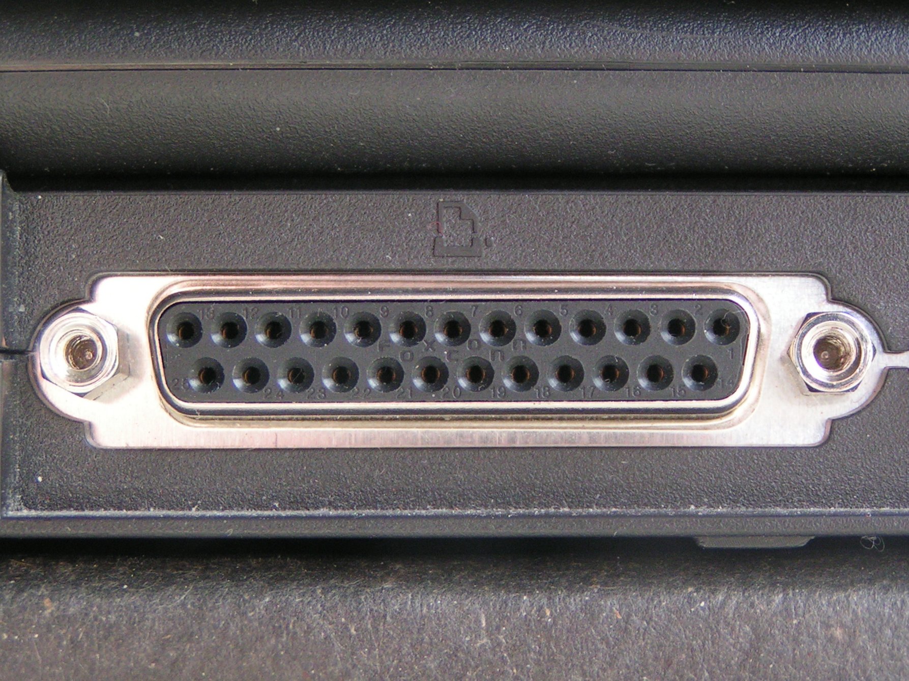
 A DB-25 connector often used for a parallel printer port on IBM PC compatible computers, with the printer icon. | |||
| Type | Point-to-point | ||
|---|---|---|---|
| Production history | |||
| Designer | Centronics, IBM | ||
| Designed | 1970–1981 | ||
| Manufacturer | Centronics, Dataproducts, Intel, IBM, Compaq, Nortel, etc | ||
| General specifications | |||
| Length | 2.3 cm (0.91 in) | ||
| Hot pluggable | Usually not | ||
| External | Yes | ||
| Cable | Usually up to 25 wires including ground; optionally shielded | ||
| Pins | 8 data, 4 output control, 5 input control, 8 ground | ||
| Connector | DB-25, DB25F, "Centronics" 36-pin Amphenol, DC-37, others | ||
| Electrical | |||
| Signal | 0 to +5.0 volt DC | ||
| Earth | Dedicated pins | ||
| Max. voltage | 5 volts DC | ||
| Data | |||
| Data signal | Parallel | ||
| Width | Variable | ||
| Bitrate |
PP: 150 kB/s,[1] EPP: 2 MB/s ECP: 2.5 MB/s | ||
| Max. devices | 2, unless devices provide passthrough | ||
| Protocol | Application dependent | ||
| Pinout | |||
 | |||
| IBM PC-compatible parallel port pinout | |||


In computing, a parallel port is a type of interface found on early computers (personal and otherwise) for connecting peripherals. The name refers to the way the data is sent; parallel ports send multiple bits of data at once (parallel communication), as opposed to serial communication, in which bits are sent one at a time. To do this, parallel ports require multiple data lines in their cables and port connectors and tend to be larger than contemporary serial ports, which only require one data line.
There are many types of parallel ports, but the term has become most closely associated with the printer port or Centronics port found on most personal computers from the 1970s through the 2000s. It was an industry de facto standard for many years, and was finally standardized as IEEE 1284 in the late 1990s, which defined the Enhanced Parallel Port (EPP) and Extended Capability Port (ECP) bi-directional versions. Today, the parallel port interface is virtually non-existent in new computers because of the rise of Universal Serial Bus (USB) devices, along with network printing using Ethernet and Wi-Fi connected printers.
The parallel port interface was originally known as the Parallel Printer Adapter on IBM PC-compatible computers. It was primarily designed to operate printers that used IBM's eight-bit extended ASCII character set to print text, but could also be used to adapt other peripherals. Graphical printers, along with a host of other devices, have been designed to communicate with the system.
History
[edit]Centronics
[edit]An Wang, Robert Howard and Prentice Robinson began development of a low-cost printer at Centronics, a subsidiary of Wang Laboratories that produced specialty computer terminals. The printer used the dot matrix printing principle, with a print head consisting of a vertical row of seven metal pins connected to solenoids. When power was applied to the solenoids, the pin was pushed forward to strike the paper and leave a dot. To make a complete character glyph, the print head would receive power to specified pins to create a single vertical pattern, then the print head would move to the right by a small amount, and the process repeated. On their original design, a typical glyph was printed as a matrix seven high and five wide, while the "A" models used a print head with 9 pins and formed glyphs that were 9 by 7.[2]
This left the problem of sending the ASCII data to the printer. While a serial port does so with the minimum of pins and wires, it requires the device to buffer up the data as it arrives bit by bit and turn it back into multi-bit values. A parallel port makes this simpler; the entire ASCII value is presented on the pins in complete form. In addition to the eight data pins, the system also needed various control pins as well as electrical grounds. Wang happened to have a surplus stock of 20,000 Amphenol 36-pin micro ribbon connectors that were originally used for one of their early calculators. The interface only required 21 of these pins, the rest were grounded or not connected. The connector has become so closely associated with Centronics that it is now popularly known as the "Centronics connector".[3]
The Centronics Model 101 printer, featuring this connector, was released in 1970.[3] The host sent ASCII characters to the printer using seven of eight data pins, pulling them high to +5V to represent a 1. When the data was ready, the host pulled the STROBE pin low, to 0 V. The printer responded by pulling the BUSY line high, printing the character, and then returning BUSY to low again. The host could then send another character. Control characters in the data caused other actions, like the CR or EOF. The host could also have the printer automatically start a new line by pulling the AUTOFEED line high, and keeping it there. The host had to carefully watch the BUSY line to ensure it did not feed data to the printer too rapidly, especially given variable-time operations like a paper feed.[2][4]
The printer side of the interface quickly became an industry de facto standard, but manufacturers used various connectors on the system side, so a variety of cables were required. For example, NCR used the 36-pin micro ribbon connector on both ends of the connection, early VAX systems used a DC-37 connector, Texas Instruments used a 25-pin card edge connector and Data General used a 50-pin micro ribbon connector. When IBM implemented the parallel interface on the IBM PC, they used the DB-25F connector at the PC-end of the interface, creating the now familiar parallel cable with a DB25M at one end and a 36-pin micro ribbon connector at the other.
In theory, the Centronics port could transfer data as rapidly as 75,000 characters per second. This was far faster than the printer, which averaged about 160 characters per second, meaning the port spent much of its time idle. The performance was defined by how rapidly the host could respond to the printer's BUSY signal asking for more data. To improve performance, printers began incorporating buffers so the host could send them data more rapidly, in bursts. This not only reduced (or eliminated) delays due to latency waiting for the next character to arrive from the host, but also freed the host to perform other operations without causing a loss of performance. Performance was further improved by using the buffer to store several lines and then printing in both directions, eliminating the delay while the print head returned to the left side of the page. Such changes more than doubled the performance of an otherwise unchanged printer, as was the case on Centronics models like the 102 and 308.[4]
IBM
[edit]IBM released the IBM Personal Computer in 1981 and included a variant of the Centronics interface— only IBM logo printers (rebranded from Epson) could be used with the IBM PC.[5] IBM standardized the parallel cable with a DB25F connector on the PC side and the 36-pin Centronics connector on the printer side. Vendors soon released printers compatible with both standard Centronics and the IBM implementation.
The original IBM parallel printer adapter for the IBM PC of 1981 was designed to support limited bidirectionality, with 8 lines of data output and 4 lines of data input.[citation needed] This allowed the port to be used for other purposes, not just output to a printer. This was accomplished by allowing the data lines to be written to by devices on either end of the cable, which required the ports on the host to be bidirectional. This feature saw little use, and was removed in later revisions of the hardware. Years later, in 1987, IBM reintroduced the bidirectional interface with its IBM PS/2 series, where it could be enabled or disabled for compatibility with applications hardwired not to expect a printer port to be bidirectional.
Bi-Tronics
[edit]As the printer market expanded, new types of printing mechanisms appeared. These often supported new features and error conditions that could not be represented on the existing port's relatively few status pins. While the IBM solution could support this, it was not trivial to implement and was not at that time being supported. This led to the Bi-Tronics system, introduced by HP on their LaserJet 4Si in April 1993.[6] This used four existing status pins, ERROR, SELECT, PE and BUSY to represent a nibble, using two transfers to send an 8-bit value. Bi-Tronics mode, now known as nibble mode, was indicated by the host pulling the SELECT line high, and data was transferred when the host toggles the AUTOFEED low. Other changes in the handshaking protocols improved performance, reaching 400,000 cps to the printer, and about 50,000 cps back to the host.[7] A major advantage of the Bi-Tronics system is that it can be driven entirely in software in the host, and uses otherwise unmodified hardware - all the pins used for data transfer back to the host were already printer-to-host lines.
EPP and ECP
[edit]The introduction of new devices like scanners and multi-function printers demanded much more performance than either the Bi-Tronics or IBM style backchannels could handle. Two other standards have become more popular for these purposes. The Enhanced Parallel Port (EPP), originally defined by Zenith Electronics, is similar to IBM's byte mode in concept, but changes details of the handshaking to allow up to 2 MB/s.[8] The Extended Capability Port (ECP) is essentially an entirely new port in the same physical housing that also adds direct memory access based on ISA and run-length encoding to compress the data, which is especially useful when transferring simple images like faxes or black-and-white scanned images. ECP offers performance up to 2.5 MB/s in both directions.[9]
All of these enhancements are collected as part of the IEEE 1284 standard. The first release in 1994 included original Centronics mode ("compatibility mode"), nibble and byte modes, as well as a change to the handshaking that was already widely used; the original Centronics implementation called for the BUSY lead to toggle with each change on any line of data (busy-by-line), whereas IEEE 1284 calls for BUSY to toggle with each received character (busy-by-character). This reduces the number of BUSY toggles and the resulting interruptions on both sides. A 1997 update standardized the printer status codes. In 2000, the EPP and ECP modes were moved into the standard, as well as several connector and cable styles, and a method for daisy chaining up to eight devices from a single port.[9]
Some host systems or print servers may use a strobe signal with a relatively low voltage output or a fast toggle. Any of these issues might cause no or intermittent printing, missing or repeated characters or garbage printing. Some printer models may have a switch or setting to set busy by character; others may require a handshake adapter.[citation needed]
Dataproducts
[edit]Dataproducts introduced a very different implementation of the parallel interface for their printers. It used a DC-37 connector on the host side and a 50 pin connector on the printer side—either a DD-50 (sometimes incorrectly referred to as a "DB50") or the block shaped M-50 connector; the M-50 was also referred to as Winchester.[10][11] Dataproducts parallel was available in a short-line for connections up to 50 feet (15 m) and a long-line version using differential signaling for connections to 500 feet (150 m). The Dataproducts interface was found on many mainframe systems up through the 1990s, and many printer manufacturers offered the Dataproducts interface as an option.
A wide variety of devices were eventually designed to operate on a parallel port. Most devices were uni-directional (one-way) devices, only meant to respond to information sent from the PC. However, some devices such as Zip drives were able to operate in bi-directional mode. Printers also eventually took up the bi-directional system, allowing various status report information to be sent.
Historical uses
[edit]
Before the advent of USB, the parallel interface was adapted to access a number of peripheral devices other than printers. One early use of the parallel port was for dongles used as hardware keys which were supplied with application software as a form of software copy protection. Other uses included optical disc drives such as CD readers and writers, Zip drives, scanners, tape drives,[12] external modems, gamepads, and joysticks. Some of the earliest portable MP3 players required a parallel port connection for transferring songs to the device.[13] Adapters were available to run SCSI devices via parallel. Other devices such as EPROM programmers and hardware controllers could be connected via the parallel port.
Interfaces
[edit]Most PC-compatible systems in the 1980s and 1990s had one to three ports, with communication interfaces defined like this:
- Logical parallel port 1: I/O port 0x3BC to 0x3BF, IRQ 7 (usually in monochrome graphics adapters)
- Logical parallel port 2: I/O port 0x378 to 0x37F, IRQ 7 (dedicated IO cards or using a controller built into the mainboard)
- Logical parallel port 3: I/O port 0x278 to 0x27F, IRQ 5 (dedicated IO cards or using a controller built into the mainboard)
If no printer port is present at 0x3BC, the second port in the row (0x378) becomes logical parallel port 1 and 0x278 becomes logical parallel port 2 for the BIOS. Sometimes, printer ports are jumpered to share an interrupt despite having their own IO addresses (i.e. only one can be used interrupt-driven at a time). In some cases, the BIOS supports a fourth printer port as well, but the base address for it differs significantly between vendors. Since the reserved entry for a fourth logical printer port in the BIOS Data Area (BDA) is shared with other uses on PS/2 machines and with S3 compatible graphics cards, it typically requires special drivers in most environments. Under DR-DOS 7.02 the BIOS port assignments can be changed and overridden using the LPT1, LPT2, LPT3 (and optionally LPT4) CONFIG.SYS directives.
Access
[edit]DOS-based systems make the logical parallel ports detected by the BIOS available under device names such as LPT1, LPT2 or LPT3 (corresponding with logical parallel port 1, 2, and 3, respectively). These names derive from terms like Line Print Terminal, Local Print Terminal (both abbreviated as LPT), or Line Printer. A similar naming convention was used on ITS, DEC systems, as well as in CP/M and 86-DOS (LST).
In DOS, the parallel printers could be accessed directly on the command line. For example, the command "TYPE C:\AUTOEXEC.BAT > LPT1:" would redirect the contents of the AUTOEXEC.BAT file to the printer port. A PRN device was also available as an alias for LPT1. Some operating systems (like Multiuser DOS) allow to change this fixed assignment by different means. Some DOS versions use resident driver extensions provided by MODE, or users can change the mapping internally via a CONFIG.SYS PRN=n directive (as under DR-DOS 7.02 and higher). DR-DOS 7.02 also provides optional built-in support for LPT4 if the underlying BIOS supports it.
PRN, along with CON, AUX and a few others are invalid file and directory names in DOS and Windows, even on Windows XP and later. This set of invalid file and directory names also affects Windows 95 and 98, which had an MS-DOS device in path name vulnerability in which it causes the computer to crash if the user types "C:\CON\CON", "C:\PRN\PRN" or "C:\AUX\AUX" in the Windows Explorer address bar or via the Run command.[citation needed] Microsoft has since released a patch to fix this issue, however new installations of Windows 95 and 98 are not patched with this fix and will still have this issue.
A special "PRINT" command also existed to achieve the same effect. Microsoft Windows still refers to the ports in this manner in many cases, though this is often fairly hidden.
In SCO UNIX and Linux, the first parallel port is available via the filesystem as /dev/lp0. Linux IDE devices can use a paride (parallel port IDE) driver.[14]
Notable consumer products
[edit]
- The Iomega ZIP drive
- The Snappy Video SnapShot video capture device[15]
- MS-DOS 6.22's INTERLNK and INTERSRV drive sharing utility
- The Covox Speech Thing audio device
- The OPL2LPT and OPL3LPT audio devices
Current use
[edit]For consumers, USB and computer networks have replaced the parallel printer port, for connections both to printers and to other devices.
Many manufacturers of personal computers and laptops consider parallel to be a legacy port and no longer include the parallel interface. Smaller machines have less room for large parallel port connectors. USB-to-parallel adapters are available that can make parallel-only printers work with USB-only systems. There are PCI (and PCI-express) cards that provide parallel ports. There are also some print servers that provide an interface to parallel ports through a network. USB-to-EPP chips can also allow other non-printer devices to continue to work on modern computers without a parallel port.[16]
For electronics hobbyists the parallel port is still often the easiest way to connect to an external circuit board. It is faster than the other common legacy port (serial port), requires no serial-to-parallel converter, and requires far less interface logic and software than a USB target interface. However, Microsoft operating systems later than Windows 95/98 prevent user programs from directly writing to or reading from the LPT without additional software (kernel extensions).[17]
CNC Milling Machines also often make use of the parallel port to directly control the machine's motors and attachments, especially with LinuxCNC OS.
IBM PC implementation
[edit]Port addresses
[edit]Traditionally IBM PC systems have allocated their first three parallel ports according to the configuration in the table below (if all three printer ports exist).
| PORT NO | Interrupt # | Starting I/O | Ending I/O |
|---|---|---|---|
#1 |
IRQ 7 |
0x3BC[18] |
0x3BF
|
#2 |
IRQ 7 |
0x378[18] |
0x37F
|
#3 |
IRQ 5 |
0x278[18] |
0x27F
|
If there is an unused slot, the port addresses of the others are moved up. (For example, if a port at 0x3BC does not exist, the port at 0x378 will then become the first logical parallel port.)[18] The base address 0x3BC is typically supported by printer ports on MDA and Hercules display adapters, whereas printer ports provided by the mainboard chipset or add-on cards rarely allow to be configured to this base address. Therefore, in absence of a monochrome display adapter, a common assignment for the first logical parallel port (and therefore also for the corresponding LPT1 DOS device driver) today is 0x378, even though the default is still 0x3BC (and would be selected by the BIOS if it detects a printer port at this address). The IRQ lines are typically configurable in the hardware as well. Assigning the same interrupt to more than one printer port should be avoided and will typically cause one of the corresponding ports to work in polled mode only. The port addresses assigned to slot can be determined by reading the BIOS Data Area (BDA) at 0000h:0408h.
Bit-to-pin mapping for the Standard Parallel Port (SPP):
| Address | MSB | LSB | |||||||
|---|---|---|---|---|---|---|---|---|---|
| Bit: | 7 | 6 | 5 | 4 | 3 | 2 | 1 | 0 | |
Base (Data port) |
Pin: | 9 | 8 | 7 | 6 | 5 | 4 | 3 | 2 |
Base+1 (Status port) |
Pin: | ~11 | 10 | 12 | 13 | 15 | |||
Base+2 (Control port) |
Pin: | ~17 | 16 | ~14 | ~1 |
~ indicates a hardware inversion of the bit.
Program interface
[edit]In versions of Windows that did not use the Windows NT kernel (as well as DOS and some other operating systems), programs could access the parallel port with simple outportb() and inportb() subroutine commands. In operating systems such as Windows NT and Unix (NetBSD, FreeBSD, Solaris, 386BSD, etc.), the microprocessor is operated in a different security ring, and access to the parallel port is prohibited, unless using the required driver. This improves security and arbitration of device contention. On Linux, inb() and outb() can be used when a process is run as root and an ioperm() command is used to allow access to its base address; alternatively, ppdev allows shared access and can be used from userspace if the appropriate permissions are set.
The cross-platform library for parallel port access, libieee1284, also is available on many Linux distributions and provides an abstract interface to the parallel ports of the system. Access is handled in an open-claim-release-close sequence, which allows for concurrent access in userspace.
Pinouts
[edit]The older parallel printer ports had an 8-bit data bus and four pins for control output (Strobe, Linefeed, Initialize, and Select In), and five more for control input (ACK, Busy, Select, Error, and Paper Out). Its data transfer speed is at 150 kB/s.[1] It is possible for a parallel port to have a speed of 300 KB/s.[19]
The newer EPPs (Enhanced Parallel Ports) have an 8-bit data bus, and the same control pins as the normal parallel printer port. Newer ports reach speeds of up to 2 MB/s.[20][better source needed]
Pinouts for parallel port connectors are:

| Pin No (DB25) | Pin No (36 pin) | Signal name | Direction | Register - bit | Inverted |
|---|---|---|---|---|---|
| 1 | 1 | Strobe | In/out | Control-0 | Yes |
| 2 | 2 | Data0 | Out | Data-0 | No |
| 3 | 3 | Data1 | Out | Data-1 | No |
| 4 | 4 | Data2 | Out | Data-2 | No |
| 5 | 5 | Data3 | Out | Data-3 | No |
| 6 | 6 | Data4 | Out | Data-4 | No |
| 7 | 7 | Data5 | Out | Data-5 | No |
| 8 | 8 | Data6 | Out | Data-6 | No |
| 9 | 9 | Data7 | Out | Data-7 | No |
| 10 | 10 | Ack | In | Status-6 | No |
| 11 | 11 | Busy | In | Status-7 | Yes |
| 12 | 12 | Paper-Out | In | Status-5 | No |
| 13 | 13 | Select | In | Status-4 | No |
| 14 | 14 | Linefeed | In/out | Control-1 | Yes |
| 15 | 32 | Error | In | Status-3 | No |
| 16 | 31 | Reset | In/out | Control-2 | No |
| 17 | 36 | Select-Printer | In/out | Control-3 | Yes |
| 18-25 | 19-30,33,17,16 | Ground | - | - | - |
Inverted lines are true on logic low. If they are not inverted, then logic high is true.
Pin 25 on the DB25 connector might not be connected to ground on modern computers.[dubious – discuss]
See also
[edit]- Device file
- Serial port
- Parallel communication
- IEEE 1284, better known as "Enhanced Parallel Port"
Hardware IC chips:
- For host computer, see Super I/O
- For peripheral side, example parallel port interface chips: PPC34C60 (SMSC) and W91284PIC (Warp Nine)
- For USB-printer purpose, example USB chips: PL-2305 (Prolific) and CH341 (QinHeng)
References
[edit]- ^ a b James, Kevin. PC interfacing and data acquisition : techniques for measurement, instrumentation and control. Oxford; Boston : Newnes, 2000. ISBN 9780750646246. p. 256
- ^ a b Centronics model 306 Technical Manual. Centronics. 1976.
- ^ a b Webster, Edward C. (2000). Print Unchained: Fifty Years of Digital Printing: A Saga of Invention and Enterprise. West Dover, VT: DRA of Vermont. ISBN 0-9702617-0-5.
- ^ a b Centronics 101, 120A, 101AL, 102A, 306 Printers (PDF). Archived (PDF) from the original on 2016-10-03.
- ^ Durda IV, Frank (2004). "Centronics and IBM Compatible Parallel Printer Interface Pin Assignment Reference". Archived from the original on 2007-09-13. Retrieved 2007-10-05.
- ^ HP Corporate Archives (2004-05-24). "Twenty Years of Innovation: HP LaserJet and Inkjet Printers 1984–2004" (PDF). www.hp.com. HP. Archived from the original (PDF) on 2007-12-02. Retrieved 2021-11-05.
- ^ "Nibble Mode". Department of Chemistry, Ajou University. Archived from the original on 2017-04-06. Retrieved 2016-10-11.
- ^ EP 0640229 Buxton, C.L. / Kohtz, R.A. / Zenith Data Systems Corp.: Enhanced parallel port. filing date 15 May 1992
- ^ a b IEEE 1284: Parallel Ports (PDF) (Technical report). Lava. 2002. Archived from the original (PDF) on 23 May 2006. Retrieved 2 November 2007.
- ^ "Dataproducts D-Sub 50 Parallel". Hardware Book. Archived from the original on 2007-12-14. Retrieved 2008-01-25.
- ^ "Dataproducts M/50 Parallel". Hardware Book. Archived from the original on 2007-12-14. Retrieved 2008-01-25.
- ^ Michael Byrd (2013). Handbook of Computer Troubleshooting. UNKNO. ISBN 978-1888998993.
- ^ Mitskaniouk, Oleg (2000-06-19). "The D-Link DMP-100 MP3 Player". Target PC Magazine. p. 2. Archived from the original on 2015-05-01. Retrieved 2012-07-20.
- ^
Barkakati, Naba (2006). Linux All-in-One Desk Reference For Dummies (2 ed.). John Wiley & Sons. p. 482. ISBN 9780471793137. Retrieved 2015-09-11.
Some IDE devices use a parallel port IDE adapter — that's what the PARIDE option refers to.
- ^ "Play Snappy Video SnapShot still-image capture adapter Series Specifications". CNET. Archived from the original on 2017-08-06. Retrieved 2017-08-06.
- ^ "Parallel port flatbed scanner works under USB on Win9x (Archive)". Archived from the original on 2012-06-30. Retrieved 2012-06-30.
{{cite web}}: CS1 maint: bot: original URL status unknown (link) - ^ "Inpout32.DLL for Windows 98/2000/NT/XP". Archived from the original on 2014-03-14. Retrieved 2014-03-14.
- ^ a b c d Frank Van Gilluwe, The Undocumented PC, 1994, page 703, ISBN 0-201-62277-7
- ^ Thompson, Robert Bruce; Thompson, Barbara Fritchman (24 July 2003). PC Hardware in a Nutshell: A Desktop Quick Reference. "O'Reilly Media, Inc.". ISBN 978-0-596-55234-3.
- ^ Parallel Port Definition Archived 2013-01-03 at the Wayback Machine, Techopedia
- Axelson, Jan (2000). Parallel Port Complete. Jan Axelson's Lakeview Research. ISBN 0-9650819-1-5.
- The (Linux) Parallel Port Subsystem by Tim Waugh Archived 2020-09-09 at the Wayback Machine
External links
[edit]- Parallel Port (from BeyondLogic.org) standard, enhanced (EPP), extended (ECP), examples[permanent dead link]
- EPP parallel printer port data capture project
- Linux I/O port programming mini-HOWTO
- The Linux 2.4 Parallel Port Subsystem Archived 2021-02-11 at the Wayback Machine
- Parallel Port interfacing with Windows NT/2000/XP
- Parallel port complete: programming, interfacing & using the PC's parallel printer port
- PyParallel - API for Python programming language
- Linux ppdev reference Archived 2021-02-11 at the Wayback Machine
- libieee1284 homepage
- MSDN: Roadmap for Developing Parallel Device Drivers
Parallel port
View on GrokipediaOverview
Definition and Basic Operation
The parallel port is a hardware communication interface that enables the simultaneous transmission of multiple bits of data over separate wires, allowing for parallel data transfer in contrast to serial ports, which send bits sequentially along a single wire.[5][6] Originally developed as the Centronics interface in the mid-1960s by Centronics Data Computer Corporation, it was designed primarily as an 8-bit unidirectional connection for linking computers to printers.[3] It became a de facto standard for personal computers following its adoption by IBM for the IBM PC in 1981, facilitating reliable output to dot-matrix and other early printers.[7] In basic operation, the parallel port uses eight data lines to send one byte (8 bits) at a time from the host to the peripheral, with the host asserting a STROBE control signal to indicate valid data, which the receiving device latches on the rising edge.[5][4] The peripheral then responds with status signals, such as ACKNOWLEDGE to confirm receipt and BUSY to indicate it is processing data and cannot accept more, ensuring handshaking for error-free transfer.[5] Later implementations introduced bidirectional capability on the data lines, allowing data flow in both directions, though the original design was output-only.[3] During the 1970s through the 1990s, parallel ports were widely used for connecting printers, scanners, and other peripherals to personal computers, serving as a primary I/O method before USB dominance.[7][4] A key advantage over contemporary serial ports was its higher transfer speed, reaching up to 150 KB/s in standard mode, compared to serial rates often limited to around 14 KB/s.[7][5] Over time, it evolved into enhanced modes such as EPP and ECP for improved performance.[3]Types and Standards
The Standard Parallel Port (SPP), also known as the original Centronics parallel port, serves as the foundational unidirectional interface for 8-bit data output from host to peripheral, utilizing a 25-pin DB-25 connector on the computer side.[3] This design, derived from early printer interfaces, supports transfer rates up to 150 kB/s in theory but typically achieves around 10 kB/s due to software overhead and handshaking limitations.[3] It includes 8 data lines, 4 control lines for signaling, and 5 status lines for peripheral feedback, making it suitable primarily for output-only applications like basic printing.[3] To address the limitations of SPP's unidirectionality and speed, the Enhanced Parallel Port (EPP) was developed in 1991 by Intel, Xircom, and Zenith Data Systems as a bidirectional protocol supporting higher data throughput for non-printer peripherals such as scanners and external storage devices.[8] EPP achieves transfer rates of 500 kB/s to 2 MB/s by emulating microprocessor bus-like signaling, including automatic address and data strobes, and provides five additional registers for direct hardware access without CPU intervention.[3] This made it particularly effective for devices requiring frequent bidirectional data exchanges, though it required compatible hardware and drivers.[8] The Extended Capabilities Port (ECP), introduced in 1992 by Microsoft and Hewlett-Packard, further advanced parallel port capabilities with built-in support for Direct Memory Access (DMA), FIFO buffering, and run-length encoding to optimize data compression and flow control.[8] Capable of speeds up to 2 MB/s (or 2.4 MB/s in DMA mode on ISA buses), ECP emphasizes enhanced printer performance through Plug and Play compatibility and efficient handshaking, reducing CPU load during transfers.[3] Like EPP, it supports bidirectional operation but prioritizes streaming data scenarios over random access.[8] The IEEE 1284 standard, ratified in 1994 by the Institute of Electrical and Electronics Engineers, provided a comprehensive framework unifying prior implementations into a single bidirectional specification compliant with existing hardware.[3] It defines five operational modes—Compatibility (emulating SPP for forward-only transfers), Nibble and Byte (for reverse 4-bit or 8-bit data from peripheral to host), EPP, and ECP—along with a negotiation protocol allowing devices to select the optimal mode at connection. The standard also specifies three cable connector types: Type A (DB-25 for computers), Type B (36-pin Centronics-style for printers), and Type C (mini 36-pin for portable devices), ensuring interoperability while supporting speeds up to 2 MB/s depending on the mode.[3] Before widespread adoption of Centronics and IEEE standards, proprietary parallel port variants emerged, such as the Dataproducts interface commonly used in early line printers and featuring a 36-pin connector for ASCII-based 7- or 8-bit parallel data transmission.[9] These implementations, often tailored for specific printer models, included custom handshaking protocols like REQ-ACK but lacked the universality of later standards, leading to compatibility adapters in mixed environments.[10]| Type/Standard | Directionality | Max Speed | Key Introduction Year | Primary Use Case | Citation |
|---|---|---|---|---|---|
| SPP (Centronics-based) | Unidirectional (output) | 150 kB/s | 1981 (IBM PC adoption) | Basic printing | [3] |
| EPP | Bidirectional | 2 MB/s | 1991 | Scanners, storage | [8] |
| ECP | Bidirectional | 2 MB/s | 1992 | Advanced printing | [8] |
| IEEE 1284 | Bidirectional (multi-mode) | 2 MB/s | 1994 | Standardized interoperability | [3] |
| Dataproducts (proprietary) | Unidirectional/Bidirectional variants | Varies (e.g., 200 kB/s) | Pre-1980s | Early line printers | [9] |
History
Early Development
The parallel port originated in the late 1960s as an 8-bit interface designed to connect dot-matrix printers to computers, addressing the limitations of slower serial connections. Robert Howard, founder of Centronics Data Computer Corporation, developed this interface in collaboration with An Wang and Prentice Robinson of Wang Laboratories, initially using a 36-pin connector to enable reliable, high-speed data transfer for the company's Model 101 printer introduced around 1970.[11][12] This innovation stemmed from the need to accelerate printer output beyond the capabilities of RS-232 serial interfaces, which typically operated at around 100 bytes per second, achieving up to 185 bytes per second through parallel transmission of an entire byte at once.[13] By the mid-1970s, the interface evolved toward greater compatibility, with host computer implementations varying but the 25-pin DB-25 connector becoming the de facto standard in 1981 with the introduction of the IBM PC to standardize cabling and integration with existing hardware.[14] During the 1970s, the parallel port saw early adoption by minicomputer manufacturers, including Wang Laboratories, which integrated it into systems for efficient peripheral connectivity, and others like Digital Equipment Corporation for line printers in business applications.[15] These implementations highlighted the port's versatility beyond printers, though its core driver remained enhancing data throughput for output devices in pre-personal computer eras. IBM later adapted the interface for its PC line in the early 1980s.PC Adoption and Enhancements
The parallel port was integrated into personal computers starting with the IBM PC model 5150 in 1981, where it was implemented as an optional expansion card compatible with the Centronics printer interface and connected via the system's I/O channel, an early form of the ISA bus.[16] This setup allowed for unidirectional data transfer to printers at rates up to 10 KB/s, using a 25-pin D-sub connector on the PC side and supporting standard control signals like strobe and busy.[16] By 1983, the IBM PC/XT model 5160 advanced this by incorporating the parallel port directly onto the system board, maintaining Centronics compatibility while leveraging the full 8-bit ISA bus for more reliable I/O operations and BIOS support via Interrupt 17h.[17] In the 1980s, enhancements introduced bidirectional capabilities to enable status feedback and limited reverse data flow from peripherals. Nibble mode, allowing 4-bit reverse transfers over the status lines for printer feedback, emerged as an early bidirectional feature in PC implementations. Byte mode followed, providing full 8-bit duplex communication by reconfiguring the data lines for input, initially supported in limited form but standardized more broadly with the IBM PS/2 series in 1987. That year, Epson adopted Bi-Tronics—a proprietary bidirectional protocol based on nibble mode—for its printers like the LQ-2500 series, enabling enhanced compatibility with PC hosts for two-way printing operations.[18] The 1990s brought significant performance upgrades through industry collaborations. The Enhanced Parallel Port (EPP), developed by Intel, Xircom, and Zenith Data Systems in 1991, extended the port's utility beyond printing by supporting high-speed bidirectional transfers up to 2 MB/s, ideal for peripherals like external storage and scanners. In 1992, Microsoft and Hewlett-Packard introduced the Extended Capabilities Port (ECP), which incorporated direct memory access (DMA) for efficient burst transfers and run-length encoding (RLE) for real-time data compression ratios up to 64:1, particularly benefiting printers and imaging devices.[19][20] These enhancements solidified the parallel port as a de facto standard across IBM PS/2 systems and compatible clones, powering a wide range of peripherals until the late 1990s, when USB began supplanting it due to superior plug-and-play features and speed.[18]Technical Implementation
Hardware Configuration
The standard parallel port on personal computers typically employs a 25-pin D-subminiature (DB-25) connector, which serves as the interface for connecting peripherals such as printers. This connector features 8 data lines assigned to pins 2 through 9, enabling parallel transmission of an 8-bit byte in a single operation. Control signals include pin 1 for the strobe signal, which pulses low to indicate valid data; pin 14 for auto-feed; pin 16 for initialize; and pin 17 for select printer input. Status lines encompass pin 10 for acknowledge, pin 11 for busy, pin 12 for paper out, pin 13 for select, and pin 15 for error, providing feedback from the peripheral to the host. Ground connections occupy the remaining pins (18-25), ensuring proper signal referencing.[21][22] Under the IEEE 1284 standard, which enhances bidirectional communication, connector variations adapt the parallel port for different roles and form factors. Type A uses the standard DB-25 male connector on the host side for compatibility with existing PC ports. Type B employs the 36-pin Centronics connector on the device side, a shielded, high-density interface originally developed for printers. Type C introduces a miniature 36-pin version, suitable for compact devices, while Type D supports proprietary high-density configurations. These variations maintain interoperability but impose cable length limits of approximately 10 feet (3 meters) for high-speed modes to minimize signal degradation.[23][24] Electrically, parallel ports operate with TTL-compatible logic levels, utilizing a voltage range of 0 to 5 volts, where logic low is 0-0.8 V and logic high is 2.4-5 V. Data transfer relies on a handshaking protocol: the host asserts the strobe signal low on pin 1 to latch the 8-bit data on pins 2-9, while the peripheral responds via the busy signal on pin 11 (high during processing) and acknowledge on pin 10 (a low pulse confirming receipt). This asynchronous mechanism ensures reliable byte-oriented communication without a shared clock.[25][26] Printer-specific variants include the 36-pin Centronics connector, which features a trapezoidal shell with two rows of 18 pins each, providing additional shielding and ground paths compared to the DB-25; it directly interfaces with the parallel port via a DB-25 to Centronics cable. For internal system integration, parallel ports were commonly implemented on ISA or PCI expansion cards, allowing multiple ports per card and connection via ribbon cables to rear-panel brackets; these cards use onboard buffers and transceivers to interface with the system's bus while exposing standard DB-25 connectors externally.[27][28][29]| DB-25 Pin | Function | Type | Description |
|---|---|---|---|
| 1 | STROBE | Control (Output) | Pulses low to latch data |
| 2-9 | DATA 0-7 | Data (Bidirectional) | 8-bit parallel data lines |
| 10 | ACK | Status (Input) | Low pulse acknowledges data receipt |
| 11 | BUSY | Status (Input) | High when peripheral is processing |
| 12 | PAPER OUT | Status (Input) | High indicates no paper |
| 13 | SELECT | Status (Input) | High when peripheral is online |
| 14 | AUTO FEED | Control (Output) | High enables line feed after print |
| 15 | ERROR | Status (Input) | Low indicates error condition |
| 16 | INIT | Control (Output) | Low pulse resets peripheral |
| 17 | SELECT IN | Control (Output) | High selects peripheral |
| 18-25 | GND | Ground | Signal reference |
Software Interface
In IBM PC-compatible systems, the parallel port is accessed via specific I/O port addresses assigned to logical ports LPT1, LPT2, and LPT3. The standard base addresses are 0x378 for LPT1, 0x278 for LPT2, and 0x3BC for LPT3, though these can vary based on system configuration or BIOS settings.[30][31] Each port uses three primary registers offset from the base address: the data register at base+0 for reading or writing 8-bit data, the status register at base+1 for monitoring peripheral feedback, and the control register at base+2 for configuring port behavior such as handshaking signals.[3][32] The status register provides key feedback from connected devices, with bits defined as follows (active low signals denoted by *):| Bit | Name | Meaning |
|---|---|---|
| 7 | BUSY* | Peripheral busy (0 = busy, cannot accept data) |
| 6 | ACK* | Acknowledge from peripheral (0 = data received) |
| 5 | PError | Paper empty or similar error (1 = error) |
| 4 | Select | Peripheral selected (1 = ready) |
| 3 | FAULT* | Fault condition (0 = error detected) |
| 2 | IRQ* | Interrupt request (0 = pending, if enabled) |
| 1-0 | Reserved | Unused |
OUT instruction writes data to an output port (e.g., to the data register for transmission or control register for signaling), while the IN instruction reads from an input port (e.g., the status register to check peripheral readiness). For example, to output a byte to LPT1 in standard SPP mode, software would write the byte to 0x378, then pulse the STROBE bit (bit 0) in the control register at 0x37A to signal the peripheral.[31][33]
Pseudocode for a simple output operation in a high-level language or OS context might look like this:
base = 0x378  // LPT1 base
data_byte = 0xAA  // Example data

// Write data
out(base + 0, data_byte)  // Data register

// Check status for busy (poll bit 7 of status)
status = in(base + 1)
while (status & 0x80 == 0):  // BUSY* low = busy
    status = in(base + 1)

// Pulse STROBE (set control bit 0 low then high)
out(base + 2, 0x0C)  // Assume initial control 0x0C (STROBE high)
out(base + 2, 0x0D)  // STROBE low
delay_microseconds(5)  // Minimum [pulse width](/page/Pulse_width)
out(base + 2, 0x0C)  // STROBE high