Hubbry Logo
Air-supported structureAir-supported structureMain
Open search
Air-supported structure
Community hub
Air-supported structure
logo
8 pages, 0 posts
0 subscribers
Be the first to start a discussion here.
Air-supported structure
from Wikipedia
Air-supported dome used as a sports and recreation venue

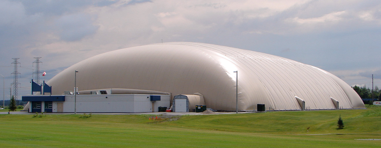
An air-supported (or air-inflated) structure is any building that derives its structural integrity from the use of internal pressurized air to inflate a pliable material (i.e. structural fabric) envelope, so that air is the main support of the structure, and where access is via airlocks.

The first air-supported structure built in history was the radome manufactured at the Cornell Aeronautical Laboratory in 1948 by Walter Bird.[1]

The concept was implemented on a large scale by David H. Geiger with the United States pavilion at Expo '70 in Osaka, Japan, in 1970.[2]

It is usually dome-shaped, since this shape creates the greatest volume for the least amount of material. To maintain structural integrity, the structure must be pressurized such that the internal pressure equals or exceeds any external pressure being applied to the structure (i.e. wind pressure). The structure does not have to be airtight to retain structural integrity—as long as the pressurization system that supplies internal pressure replaces any air leakage, the structure will remain stable.[3] All access to the structure interior must be equipped with some form of airlock—typically either two sets of parallel doors or a revolving door or both. Air-supported structures are secured by heavy weights on the ground, ground anchors, attachment to a foundation, or a combination of these.

Among its many uses are: sports and recreation facilities, warehousing, temporary shelters, and radomes. The structure can be either wholly, partial, or roof-only air supported. A fully air-supported structure can be intended to be a temporary or semi-temporary facility or permanent, whereas a structure with only an air-supported roof can be built as a permanent building.

Design

[edit]

Shape

[edit]

The shape of an air-supported structure is limited by the need to have the whole envelope surface evenly pressurized. If this is not the case, the structure will be unevenly supported, creating wrinkles and stress points in the pliable envelope which in turn may cause it to fail.[4]

In practice, any inflated surface involves a double curvature. Therefore, the most common shapes for air-supported structures are hemispheres, ovals, and half cylinders.

Structure

[edit]

The main loads acting against the air-supported envelope are internal air pressure, wind, or weight from snow build-up. The structure is actively supported at all times by blowing in more air, which requires energy.[3]

To compensate against wind force and snow load, the structure's inflation is adjusted accordingly. Modern structures have computer controlled mechanical systems that monitor dynamic loads and automatically compensate the inflation for it. The better the quality of the structure, the higher forces and weight it can endure. The best quality structures can withstand winds up to 120 mph (190 km/h) and snow weight to 40 pounds per square yard[4] (21.7 kilograms per square meter).

The interior of the Tokyo Dome exemplifies how large an area can be spanned with an air-supported roof.

The air pressure on the envelope is equal to the air pressure exerted on the inside ground, pushing the whole structure up. Therefore, it needs to be securely anchored to the ground (or to the substructure in a roof-only design).

For wide span structures cables are required for anchoring and stabilization. Anchoring requires ballast (weights). Early anchoring designs incorporated sand bags, concrete blocks, bricks, or the like, typically placed around the perimeter on the seal skirt. Most modern design structures use proprietary anchoring systems.

The danger of sudden collapse is nearly negligible, because the structure will gradually deform or sag when subject to a heavy load or force (snow or wind). Only if these warning signs are ignored or not noticed, then the build-up of an extreme load may rupture the envelope, leading to a sudden deflation and collapse.[3]

In hot or cold climates, air conditioning adds to the energy requirement. In venues visited by millions of people per year, energy consumption may be a couple gigajoules per square meter.[5]

The RCA dome in Indianapolis used to have an inflatable roof.

A common misconception is that these structures are not meant to be permanent facilities, however all major corporations participating in this industry conform to some form of The International Building Codes. To be a permanent facility these domes have to be engineered to the same building codes as a traditional structure.[citation needed]

Air-supported structures or domes are also commonly known as "bubbles".

Material

[edit]

The materials used for air-supported structures are similar to those used in tensile structures, namely synthetic fabrics such as fibreglass and polyester. In order to prevent deterioration from moisture and ultraviolet radiation, these materials are coated with polymers such as PVC and Teflon.

Depending on use and location, the structure may have inner linings made of lighter materials for insulation or acoustics. Materials used in modern air supported structures are usually translucent, therefore the use of lighting system inside the structure is often not required during the daytime.

Air pressure

[edit]

The amount of pressure required for air-supported structures is a function of the weight of the material—and the building systems suspended on it (lighting, ventilation, etc.)—and wind pressure. This amounts to less than 1% above atmospheric pressure.[6] Internal pressure is commonly measured in inches of water (inAq) and varies fractionally from 0.3 inAq for minimal inflation to 3 inAq for maximum, with 1 inAq being a standard pressurization level for normal operating conditions. In terms of the more common pounds per square inch, 1 inAq equates to a mere 0.037 psi (2.54 mBar, 254 Pa),[4]

Notable air-supported domes

[edit]

In operation

[edit]

Former notable domes

[edit]

Similar concepts

[edit]
  • Blimps, the application of this technique to airships, using the pressure differential between their lifting gas and the outside atmosphere to provide structural integrity.
  • Balloon tanks, the application of this technique to rockets, using tank pressurization for rigidity.

See also

[edit]

References

[edit]
[edit]
Revisions and contributorsEdit on WikipediaRead on Wikipedia
from Grokipedia
An air-supported structure is a structure wherein the shape is attained by air pressure and occupants of the structure are within the elevated pressure area. These structures typically consist of a flexible membrane, such as PVC-coated polyester or nylon fabric, anchored to the ground and inflated by fans or blowers to achieve the desired form without internal supports or rigid framing. The concept of air-supported structures originated in the early , with British Frederick W. Lanchester filing the first known in 1917 for a portable air-supported intended for wartime field hospitals and depots, using a low pressure differential of approximately 0.1 lb/sq in (680 Pa) to support a . Although Lanchester's designs were not widely implemented during his lifetime, the idea gained practical traction during for radar protection, culminating in the first operational air-supported designed by American Walter Bird in 1948 at the Cornell Aeronautical Laboratory. Bird's innovation led to the founding of Birdair Structures in 1956, which pioneered commercial applications, including the first large-scale civilian air-supported dome at the 1970 in , , measuring 262 feet by 460 feet. In terms of engineering principles, air-supported structures rely on a slight positive , typically 0.5 to 1.5 inches of (1.25 to 3.75 mbar or 0.02 to 0.06 psi), generated by continuous operation of air-handling units to counteract , , and other loads. The membrane must meet fire-resistance standards like NFPA 701 for flame propagation, and entry points incorporate airlocks, such as double doors or revolving mechanisms, to prevent loss. These structures can span large areas—up to several acres—making them suitable for applications including sports facilities like courts, ice rinks, and soccer fields; temporary exhibition halls; storage warehouses; and even emergency shelters. Their primary advantages include rapid assembly (often in days), low material costs compared to conventional buildings, translucency for natural lighting, and portability, with construction expenses roughly 30-50% less than traditional framed structures for similar spans. However, air-supported structures face notable challenges, such as vulnerability to punctures, (with membrane seams weakening above 300°F or 149°C), and , requiring design reinforcements for winds up to 90 mph and snow loads of 8 lb/ft². Maintenance involves constant monitoring of and periodic fabric inspections, with a typical lifespan of 20-25 years under proper care. Despite these limitations, ongoing advancements in synthetic and hybrid designs combining air support with cable or frame elements continue to expand their use in sustainable and temporary architecture worldwide. As of 2025, the market for air-supported structures is projected to grow from USD 910 million in 2024 to USD 1,560 million by 2033.

History

Early Concepts and Invention

The concept of air-supported structures originated with British engineer Frederick W. Lanchester, who filed the first known in for a portable designed for field hospitals, depots, and similar uses. This design relied on low-pressure inflation of balloon fabric to maintain the enclosure's shape without internal supports, creating a differential air pressure that supported the against external forces. The structure was intended as a lightweight, rapidly deployable alternative to traditional s, particularly for military applications during . In 1920, Lanchester refined his invention with a second for larger enclosures, such as domed exhibition halls up to 150 meters in diameter, emphasizing scalable pneumatic roofing for temporary buildings. This iteration addressed scalability by incorporating air locks and improved sealing mechanisms to sustain pressure in expansive forms, though neither resulted in constructed prototypes due to contemporary and engineering limitations. During , experimental developments in air-supported structures emerged primarily for military radomes to protect antennas from harsh weather, marking early practical tests of the concept. These efforts faced significant challenges, including material durability against environmental exposure—requiring fabrics that balanced low air permeability with —and precise pressure control to prevent collapse under varying wind loads or temperature fluctuations. The first fully realized practical air-supported structure was a engineered by Walter Bird in 1948 at the Cornell Aeronautical Laboratory in , enclosing a 16.5-meter-diameter antenna for government use. This hemispherical enclosure demonstrated the viability of pneumatic membranes for protective applications, paving the way for broader adoption in contexts.

Development and Adoption

Following the initial invention in the late 1940s, air-supported structures saw rapid adoption in military applications during the early era, particularly for protecting sensitive equipment in harsh environments. In 1956, Walter Bird founded Birdair Structures to commercialize the technology, transitioning from radomes to broader applications. In the 1950s, the U.S. deployed the first large-scale air-supported radomes as part of the Aircraft Control and Warning (AC&W) system and the Distant Early Warning (DEW) Line, spanning and . These inflatable enclosures, installed at sites like Cape Lisburne and Cape Newenham starting in 1955, shielded antennas such as the AN/FPS-3 from snow and ice buildup, which could otherwise impair signal transmission and operational reliability in subzero temperatures and high winds up to 120 mph. The design's radar transparency and quick deployment made it ideal for remote, extreme-weather locations, with over 50 stations operational across the network by 1957. The U.S. military expanded air-supported structures beyond protection into versatile temporary shelters and communication enclosures in the post-World War II period, driven by needs for mobile, lightweight solutions in diverse operations. By the early 1950s, the U.S. Army tested prototypes like the 20-foot by 40-foot inflatable shelter at , and , , evaluating its performance in cold climates for personnel housing and equipment storage; although early models faced challenges with durability and heating, they weighed significantly less than traditional frame tents, enhancing transportability for field units. In the , adoption grew for specialized uses, including radomes for communication antennas (e.g., 27-foot diameter models with quick-release valves) and support tents, which provided rapid-setup protection during the Army's programs. These developments, led by institutions such as the Natick Laboratories, emphasized advancements in materials and inflation systems to support deployments and tactical mobility. Civilian adoption emerged in the 1960s, transitioning military-proven technology to experimental large-scale applications in sports and recreation facilities, where cost-effective enclosures enabled year-round use in temperate climates. One of the earliest examples was a 1963 air-supported dome over a tennis court in the United States, which demonstrated the viability of the technology for non-military purposes, covering 10,000 square feet with minimal foundation requirements. By the late 1960s, similar enclosures proliferated for indoor tennis and swimming pools, offering economical alternatives to permanent buildings and fostering broader architectural experimentation. A pivotal milestone came in 1975 with the Pontiac Silverdome in Michigan, the first major air-supported stadium roof spanning 10 acres and seating 80,000 for the NFL's Detroit Lions; engineered by Geiger Associates, its Teflon-coated fiberglass membrane, maintained by 72 fans at 2 inches of water pressure, marked the technology's scale-up for high-profile civilian venues while building on earlier radar and shelter innovations.

Design Principles

Shape and Geometry

Air-supported structures primarily adopt hemispherical or low-profile dome shapes to optimize structural integrity under environmental loads. These forms derive from segments of spheres, where the curvature distributes internal air pressure evenly across the membrane, minimizing localized stresses. Hemispherical designs approximate a full half-sphere, while low-profile variants feature a reduced rise relative to the base span, typically with height-to-span ratios ranging from 0.25 to 0.5, which effectively reduces wind-induced uplift and drag by presenting a streamlined profile to airflow. Such geometries ensure the membrane remains in uniform tension, supported solely by the pressure differential between the interior and exterior. For applications requiring elongated enclosures, such as arenas or storage facilities, arch or configurations serve as variations on the dome principle. These consist of cylindrical barrel sections capped with hemispherical or ellipsoidal ends, allowing for extended lengths while maintaining pressure-supported rigidity along the length. The cylindrical portion follows a constant-radius , similar to a low-profile dome rotated along its axis, which accommodates larger internal spaces without proportional increases in or demands. This adaptation balances the need for volumetric capacity with aerodynamic efficiency, as the rounded ends mitigate that could otherwise amplify wind loads on straight-edged designs. Geometric principles governing these structures emphasize height-to-span of 0.25 to 0.5 for achieving optimal distribution and stability. A around 0.5 is common for minimizing aerodynamic loads, as it flattens the profile sufficiently to lower the center of while preserving sufficient internal volume. Taller enhance vertical clearance but increase susceptibility to gusts, necessitating higher anchoring forces, whereas flatter profiles (e.g., 0.25) prioritize resistance at the cost of headroom. These guide the overall form to ensure the membrane's aligns with the vector, preventing or excessive deflection under varying loads. The chosen shape profoundly influences internal volume and load-bearing capacity, with dome profiles maximizing enclosed space per unit of membrane area compared to angular alternatives. For instance, a hemispherical segment yields greater volume for a given base footprint than a conical form, as the curved surface efficiently counters outward pressure. Catenary curve profiles, particularly in perimeter anchors or ground seals, further enhance even tension distribution by conforming to the natural sag of the membrane under gravity and wind, reducing shear stresses at the base and improving overall load transfer to anchors. This integration allows structures to support snow, occupancy, or equipment loads up to several tons, scaled by the effective planform area and pressure magnitude, without requiring internal framing.

Materials and Components

Air-supported structures primarily utilize (PVC)-coated fabrics as the main envelope material, valued for their balance of tensile strength, flexibility, and resistance to (UV) radiation. These fabrics typically feature a base cloth with a applied to both sides, providing and enhanced durability against environmental exposure. The incorporates UV stabilizers to prevent degradation from , ensuring long-term performance in outdoor applications. Common weights for these fabrics in air-supported designs range from 18 to 22 ounces per (oz/yd²), offering sufficient strength for spans dictated by the structure's while maintaining lightweight properties essential for inflation efficiency. For environments requiring greater longevity or resistance to , alternatives such as (PTFE)-coated membranes are employed. PTFE provides superior chemical resistance, thermal stability, and self-cleaning properties due to its , making it suitable for harsh conditions like high winds or corrosive atmospheres. These materials exhibit high tensile strength and UV resistance, often lasting over 30 years with minimal maintenance, though they are more expensive and less flexible than PVC options. Key auxiliary components include cable nets for edge reinforcement, entrance airlocks, and grounding straps. Cable nets, often or synthetic, are integrated around the perimeter to distribute loads and prevent fabric distortion under wind or , enhancing overall structural integrity. Entrance airlocks maintain by using double-door systems that minimize air loss during access, typically constructed from the same coated fabrics with reinforced framing. Grounding straps connect the structure to earth to dissipate buildup, reducing risks from friction-induced charges in dry conditions. Fabrication involves heat-sealing individual fabric panels to form the seamless , a process that melts the PVC coating to create strong, airtight bonds. Panels are cut to precise patterns based on the structure's , then welded using or methods for uniform seams. Post-fabrication, seam integrity is tested through methods like air channel pressure testing, where inflated sections are pressurized to verify leak-proof performance and tensile hold under simulated loads.

Operation and Maintenance

Air Pressure Systems

Air pressure systems in air-supported structures utilize high-volume, low-pressure blowers to generate and sustain the internal required for maintaining the envelope's shape and integrity against gravitational and environmental forces. These systems typically employ centrifugal fans, which efficiently deliver large volumes of air at low static pressures, commonly in the range of 0.02 to 0.05 psi (140 to 350 Pa) gauge pressure under normal operating conditions. For instance, standard operational pressures for many air domes fall between 150 and 250 Pa, sufficient to counteract the structure's dead load while minimizing . This low-pressure approach distinguishes air-supported designs from higher-pressure pneumatic systems, enabling the use of lightweight, flexible membranes without excessive material stress. To ensure reliability, air pressure systems incorporate redundant blower configurations, often with at least two independent units, each capable of maintaining full independently. Automatic failover mechanisms, triggered by pressure sensors detecting a drop below a preset threshold, activate backup blowers within seconds to mitigate risks from power outages or primary unit failures. These setups are governed by building codes requiring auxiliary inflation systems that operate automatically upon loss of primary . Power supply redundancies, such as backup generators, further support continuous operation during fluctuations. The required pressure differential is fundamentally determined by balancing the structure's loads against the internal air , approximated by the basic ΔP=Wf+LeAs\Delta P = \frac{W_f + L_e}{A_s}, where ΔP\Delta P is the differential, WfW_f is the weight of the fabric , LeL_e are environmental loads (such as or ), and AsA_s is the projected surface area over which the acts. This ensures the outward force from the counters downward and lateral forces, with real-time monitoring via differential sensors placed at key points in the to maintain ΔP\Delta P within limits. These sensors, often integrated with control systems, provide continuous feedback to adjust blower speeds and alert operators to deviations, preventing deflation or over-pressurization. Ventilation is seamlessly integrated into air systems to manage indoor and without undermining , typically through dedicated air handling units that introduce filtered while compensating for added with blower modulation. These units, combining fans with heating or cooling coils, maintain 100% outside air exchange rates when needed, controlling relative below 60% and temperatures within 18–25°C for occupant comfort. By regulating through adjustable vents and ensuring compensation, the system avoids excessive infiltration or exfiltration that could alter the ΔP\Delta P. The generates horizontal outward forces on the foundation, which are resisted by anchoring systems to prevent uplift or sliding.

Anchoring and Safety Features

Air-supported structures rely on robust anchoring systems to resist uplift forces from internal pressurization and external loads like , ensuring the envelope remains taut and stable. Ballast anchorage is a widely used method, involving the placement of heavy materials such as blocks, bagged , or water-filled compartments along the perimeter to provide gravitational resistance. For a typical 30-foot structure, this may require approximately 234 pounds per linear foot to withstand 60 mph . Deadman anchors, buried arrowheads or masses connected via reinforced cables to the base, are effective in conditions, offering capacities from 600 pounds in loose to 5,000 pounds in hardpan. Helical piles, which are screw-like shafts driven into the ground and to the foundation via angle iron, provide high tensile strength for challenging sites and variable types. Perimeter cable systems enhance anchoring by forming a catenary or harness network around the envelope, distributing tension loads evenly to the ground attachments. These cables, often integrated with metal pipes in the base skirt or clamped to a foundation, maintain the structure's shape under dynamic pressures and prevent air leakage through a sealing skirt. Such systems complement the air pressure supplied by blowers, typically around 1 gauge, to achieve overall equilibrium. Positive anchorage methods like these are essential for permanent installations, while temporary setups may favor removable for mobility. Safety features in air-supported structures prioritize overpressure protection, rapid evacuation, and fire mitigation to address potential failures from power loss, severe weather, or ignition. Pressure relief valves or vents automatically discharge excess internal air to prevent envelope rupture, maintaining pressures below critical thresholds during blower surges or . Emergency deflation ports, strategically placed for quick access, enable controlled venting of 5-10% of the volume or full collapse if needed, allowing safe occupant egress—designs often incorporate air-lock effects to delay total and facilitate escape. Fire suppression integration focuses on low-pressure compatible systems, such as deluge water cannons or distribution tied to alarms, as traditional overhead sprinklers risk unintended ; envelope materials like vinyl-coated must exhibit low spread to contain incidents. Anchoring and safety designs must comply with established standards to verify performance under environmental extremes. The ASCE 7 standard outlines minimum and load criteria, including calculations like qz=0.00256KzKztKdV2q_z = 0.00256 K_z K_{zt} K_d V^2 (in lb/ft²) for external forces and reduced snow accumulation on slippery fabric surfaces, referencing specialized guidelines such as ASCE/SEI 55-16 for air-supported specifics. Fabric components adhere to NFPA 701, which tests flame propagation performance of textiles and films to ensure resistance under exposure conditions, promoting overall structural integrity and occupant protection.

Applications

Sports and Recreation Facilities

Air-supported structures are widely used in sports and recreation facilities to create enclosed environments for various athletic activities, particularly indoor tennis courts, ice rinks, and soccer fields. These structures typically cover areas ranging from 10,000 to 100,000 square feet, allowing for the enclosure of multiple playing surfaces under a single roof without internal supports that could obstruct play. For instance, a standard tennis air dome might span 300 by 200 feet (approximately 60,000 square feet), providing ample space for courts while maintaining structural integrity through constant air pressure. Similarly, ice rinks and soccer fields benefit from these domes' ability to protect against weather, with examples including a 23,000-square-foot ice skating rink enclosure and larger soccer facilities up to 100,000 square feet. A key advantage of air-supported structures in recreational settings is their facilitation of year-round in regions with variable or harsh climates, enabling consistent access to facilities regardless of external conditions. By incorporating (HVAC) systems, these domes maintain comfortable temperatures for users, reducing downtime and extending the operational season. Seasonal domes over pools exemplify this benefit, such as a 24,000-square-foot enclosure over an Olympic-sized pool that allows for extended aquatic recreation in cooler months. Their adoption in sports dates back to the , when they gained popularity for enclosing playing fields in cold climates. Engineering adaptations in these structures ensure seamless functionality for environments, including the integration of ports and scoreboards directly into the to avoid leaks. Lighting ports, often featuring skylights or sealed LED fixtures, provide natural and artificial illumination without compromising the dome's airtight integrity, while scoreboards can be mounted using proprietary sealing systems that maintain internal . These features support high-performance activities by allowing clear visibility and real-time scoring. Since the , there has been notable growth in the use of portable air-supported enclosures for e-sports arenas, aligning with the rise of competitive gaming events that require flexible, temporary venues. These lightweight, inflatable structures offer quick setup for tournaments, accommodating spectator seating, gaming stations, and broadcast equipment in controlled environments, as seen in e-sports entertainment spaces built with air dome technology.

Industrial and Temporary Uses

Air-supported structures find extensive application in industrial settings, particularly for warehousing in and . In , these structures serve as protective enclosures for storage, enabling year-round protection from environmental elements while allowing transmission for controlled cultivation environments. For instance, they are used to house grain silos or equipment, with designs supporting spans up to 300 feet wide and virtually unlimited lengths, facilitating coverage areas exceeding 200,000 square feet for large-scale operations. In , air-supported warehouses provide column-free interiors for efficient and assembly processes, often customized for temporary expansions during peak production demands. Modular extensions can be achieved by linking multiple units or extending fabric spans, minimizing downtime and construction costs compared to traditional buildings. Temporary uses of air-supported structures emphasize their rapid deployability, making them ideal for relief shelters and event pavilions. In emergency scenarios, such as , these structures offer immediate, spacious enclosures that can be erected to provide shelter, medical areas, or command centers, with assembly times typically ranging from 4 to 7 days for standard sizes up to 5,000 square meters. For events, they function as pavilions hosting exhibitions or outdoor gatherings, benefiting from quick setup that allows deployment in remote or unprepared sites using minimal groundwork like sand barriers. Their portability supports disassembly and relocation, aligning with short-term needs without permanent foundations. Key adaptations enhance the versatility of air-supported structures for both industrial and temporary applications. Integration of HVAC systems ensures controlled environments by discharging conditioned air at ground level, maintaining uniform temperatures within 1-2°F across the space, which is crucial for sensitive agricultural storage or manufacturing processes. Flooring adaptations, such as industrial-grade concrete or poured foundations, accommodate heavy loads like forklifts, providing durable, level surfaces compatible with material handling equipment. These features, combined with double-layer fabric insulation, support energy-efficient operations in varied climates. Military applications of air-supported structures were first practically implemented during as radomes to enclose and communication antennas while minimizing signal interference. These structures protected sensitive equipment in harsh conditions, including environments. Modern adaptations include field hospitals for rapid medical support in deployment zones and enclosed systems, offering quick-setup shelters that integrate with tactical operations and withstand .

Notable Examples

Current Structures

Air-supported structures continue to serve diverse functions globally, with several prominent examples operational in sports training and recreational facilities. In , universities have adopted air-supported domes to expand indoor athletic capabilities, particularly for and multi-sport programs. Columbia University's seasonal air-supported structure in offers a heated, illuminated space for hockey practices, community events, and various athletic programs, demonstrating the versatility of these temporary enclosures on urban campuses. Similarly, Drexel University's two air-supported facilities in provide safe indoor venues for sports like soccer and , benefiting both students and the local community with economical, all-weather access. These installations, often upgraded since the 1970s in similar university settings, highlight the durability and adaptability of air-supported designs for ongoing collegiate use. Europe features innovative applications of air-supported domes for temporary events, including festivals in the . Dutch companies like QuickSpace provide rental inflatable domes for conferences and festivals, with capacities supporting over 1,000 attendees in configurations up to 1,000 square meters, enabling flexible setups for seasonal cultural events across the region. In , a DUOL air-supported dome for and multi-purpose recreation further exemplifies temporary European installations that enhance local event infrastructure. Ongoing maintenance is crucial for the longevity of these structures, with well-engineered air domes typically lasting 15 to 30 years depending on material quality, environmental exposure, and upkeep. Fabric components often require replacement every 10 to 15 years, while routine inspections ensure air pressure systems and anchoring remain effective, allowing many facilities to operate continuously with periodic upgrades.

Historical Structures

The pioneering development of air-supported structures began with early designed for military protection. In 1948, engineer Walter Bird at the Cornell Aeronautical Laboratory constructed the first air-supported , a 15-meter-diameter pneumatic dome that enclosed equipment and marked the inaugural use of pressurized fabric membranes for structural purposes. This prototype demonstrated the feasibility of maintaining internal air pressure to support lightweight, translucent enclosures against environmental elements, laying the groundwork for weather-resistant applications. During and the early , air-supported were used in various military installations, but deployments primarily utilized rigid geodesic domes due to the extreme conditions. One of the most iconic historical air-supported structures was the in , opened in 1975 as the home of the team. Covering 10 acres with a Teflon-coated roof inflated by 25 industrial fans, it was the largest of its kind and hosted major events including and the . The dome operated until 2013, when a severe caused ice accumulation and tears in the aging fabric, leading to deflation; it was fully demolished in 2017 after failed redevelopment efforts due to escalating repair costs and structural obsolescence. The in , completed in 1982, exemplified the technology's application in multi-sport venues, serving as home to the and Twins with a 580,000-pound Teflon-coated roof spanning 4 hectares. Maintained by continuous air pressure from multiple fans and equipped with snow-melting ducts, it endured for nearly three decades until December 2010, when an unprecedented deposited 17 inches of snow and ice, overwhelming the membrane and causing multiple tears that led to a dramatic collapse. The structure was temporarily repaired but decommissioned after the 2013 season, making way for a replacement due to persistent vulnerability to snow loads and high operational demands. Many historical air-supported structures met their end due to material degradation from prolonged exposure to UV radiation, wind, and temperature fluctuations, which weakened the synthetic fabrics over time. Escalating costs for constant fan operation and heating—often exceeding $60,000 monthly for large domes—further strained budgets, as the uninsulated membranes offered poor compared to rigid alternatives. Additionally, the industry's shift toward hybrid and designs addressed limitations like accumulation risks and multipurpose inefficiencies, rendering pure air-supported systems largely obsolete for major venues by the early .

Advantages and Limitations

Key Benefits

Air-supported structures offer significant cost savings compared to traditional , particularly for large-span applications, with costs typically 30-70% lower due to the minimal need for and structural supports. This economic advantage stems from the use of lightweight, prefabricated membranes that require little site preparation, making them ideal for expansive facilities like sports arenas or storage units. One of the primary benefits is their rapid deployment, allowing assembly in as little as 4-7 days for standard structures, in contrast to the months or years needed for conventional construction. This quick setup is especially valuable for seasonal or temporary uses, such as event venues or emergency shelters, enabling fast response to changing needs without extensive labor or equipment. These structures provide exceptional versatility, featuring unobstructed interior spans up to 300 feet or more, which support flexible space utilization for various activities. Additionally, their modular design facilitates easy relocation and disassembly, allowing reuse at different sites with minimal downtime. In terms of energy efficiency, the air barrier and multi-layer membranes act as natural insulators, reducing heating costs by up to 30% in cold climates by minimizing heat loss. This thermal performance, combined with reduced material use, lowers overall operational expenses and environmental impact.

Challenges and Risks

Air-supported structures depend on continuous operation of blowers or fans to maintain internal pressure, typically requiring redundant power supplies to prevent . If primary power is lost and backup systems fail, the structure can and within minutes, posing severe risks to occupants and equipment inside. This vulnerability necessitates rigorous maintenance of electrical systems and protocols, including immediate evacuation upon power alerts. The membrane envelopes of these structures are susceptible to punctures from environmental hazards such as , sharp debris, or deliberate , which can lead to rapid air loss if not addressed promptly. Repair protocols involve immediate patching with specialized to seal , followed by professional inspections to assess structural , often requiring downtime and specialized technicians. Small punctures can propagate quickly under differentials, exacerbating risks without swift intervention. Environmental loads, particularly snow accumulation, impose strict limitations on air-supported structures, with designs typically rated for snow loads up to 50 psf before requiring intervention. Exceeding this threshold can cause sagging, tears, or total failure, often necessitating integrated de-icing systems like heated air circulation or mechanical to shed loads safely. In regions with heavy snowfall, operators must monitor and increase internal pressure to counteract buildup, as uncontrolled accumulation around the perimeter can generate side forces leading to . Regulatory compliance presents additional hurdles for air-supported structures, especially semi-permanent installations that blur lines between temporary and fixed buildings. ordinances often classify them as temporary structures, requiring special permits, site-specific approvals, and adherence to codes like the International Building Code Chapter 31, which mandates wind resistance up to 90 mph and fireproofing per NFPA 701. These requirements can delay deployment and increase costs. Furthermore, heightened fire risks due to the fabric's flammability result in elevated premiums, as insurers factor in rapid spread potential and evacuation challenges during incidents.

Air-Inflated Structures

Air-inflated structures derive their rigidity from pressurized air-filled tubes, beams, or that form an internal framework supporting an outer fabric membrane, maintaining the interior at . In contrast, pure air-supported systems depend entirely on low-pressure inflation of the entire envelope to generate tension for structural . This allows air-inflated structures to avoid the need for airlocks or controlled entry points, as the enclosed does not require differential to stay upright. Key design differences include the use of compartmentalized inflation in air-inflated systems, where individual beams or arches are pressurized separately at levels typically ranging from 0.5 to 2 psi to achieve , compared to the uniform low-pressure (around 0.02 to 0.05 psi or 0.14 to 0.34 mbar) in air-supported structures. These inflated elements often consist of double-layered fabrics with internal bladders for airtightness, enabling modular and easier repairs. The outer skin, draped over the frame, provides weatherproofing without bearing primary loads. Representative examples of air-inflated structures include bounce houses, where continuous blower inflation maintains the walls and bouncing surfaces as a self-contained frame, and smaller tents featuring inflatable poles or arches for rapid setup in or temporary applications. These are commonly deployed for recreational, , or short-term uses due to their portability and simplicity. Air-inflated structures offer advantages over air-supported designs in puncture resistance, as damage to a single pressurized compartment affects only localized support rather than the entire structure, facilitated by high-density weaves and rip-stop fabrics in the beams. They also eliminate the need for constant blowers to maintain across the full , relying instead on targeted that reduces use and allows intermittent operation or manual top-ups in some configurations. Membrane materials like PVC-coated are shared with air-supported systems for durability and flexibility.

Other Tension Membrane Systems

Ethylene tetrafluoroethylene () cushions represent a prominent alternative to pure air-supported structures, utilizing pneumatic panels that maintain tension through low-pressure inflation rather than full enclosure pressurization. These multi-layer air pillows, typically consisting of two or three films sealed at the edges and inflated to form cushions up to 2 meters deep, provide high translucency—allowing up to 95% light transmission—while offering comparable to at a fraction of the weight. In the in , , completed in 2001, over 800 such hexagonal and triangular ETFE cushions cover a series of biomes spanning 15,000 square meters, supported by a that distributes loads without relying on continuous air pressure across the entire structure. Cable-net facades employ tensioned membranes stretched over a grid of pre-stressed cables anchored to rigid frames or masts, achieving structural stability through fixed cable tension rather than dynamic inflation. This system allows for expansive, curved surfaces with minimal material use, often incorporating translucent or PTFE fabrics for weatherproofing and aesthetics. A notable example is the Khan Shatyr Entertainment Centre in , , designed by Foster + Partners and opened in 2010, where a 150-meter-high central mast supports a cable-net lattice clad in a three-layer ETFE envelope covering 20,000 square meters, creating an undulating tent-like form that withstands extreme continental climates. Hybrid systems integrate elements of air support with mechanical tension components, such as masts and cables, to enable convertible or semi-permanent enclosures that can adapt to varying conditions. In these designs, air inflation assists in shaping or stabilizing the membrane, while cables and supports handle primary loads, facilitating retractability or modularity. The Shaded Dome, a patented semi-permanent facility developed by ZJA | Zwarts & Jansma Architects, combines an inner air-supported PVC membrane dome with an outer tensile shade structure separated by an inflatable grid, covering up to 10,000 square meters and suitable for large events such as Olympic training facilities. Similarly, the in , , features a using a pre-stressed cable-truss system with tensioned PTFE membranes, spanning 18,000 square meters and operable in under 10 minutes to convert the space for indoor-outdoor use. In June 2025, Tensile Fabric Structures launched a new inflatable membrane dome system aimed at disaster relief and large-scale events. These systems differ fundamentally from air-supported structures by relying on fixed tension from cables, frames, or partial inflation, which permits permanent or semi-permanent installations with reduced energy demands for pressure maintenance and enhanced resistance to punctures or power failures. While air-supported designs use uniform internal pressure for form and load-bearing, tension membrane alternatives distribute forces through engineered prestress, enabling greater architectural flexibility and integration with conventional building elements, though they often require more initial fabrication complexity.

References

Add your contribution
Related Hubs
User Avatar
No comments yet.