Synchronous motor
Synchronous motor
Main page
2192566

Synchronous motor

logo
Community Hub0 subscribers
Read side by side
from Wikipedia
Miniature synchronous motor used in analog clocks. The rotor is made of permanent magnet.
Small synchronous motor with integral stepdown gear from a microwave oven

A synchronous electric motor is an AC electric motor in which, at steady state,[1] the rotation of the shaft is synchronized with the frequency of the supply current; the rotation period is exactly equal to an integer number of AC cycles. Synchronous motors use electromagnets as the stator of the motor which create a magnetic field that rotates in time with the oscillations of the current. The rotor with permanent magnets or electromagnets turns in step with the stator field at the same rate and as a result, provides the second synchronized rotating magnet field. Doubly fed synchronous motors use independently-excited multiphase AC electromagnets for both rotor and stator.[2]

Synchronous and induction motors are the most widely used AC motors. Synchronous motors rotate at a rate locked to the line frequency since they do not rely on induction to produce the rotor's magnetic field. Induction motors require slip: the rotor must rotate at a frequency slightly slower than the AC alternations in order to induce current in the rotor.

Small synchronous motors are used in timing applications such as in synchronous clocks, timers in appliances, tape recorders and precision servomechanisms in which the motor must operate at a precise speed; accuracy depends on the power line frequency, which is carefully controlled in large interconnected grid systems.

Synchronous motors are available in self-excited, fractional[3] to industrial sizes.[1] In the fractional power range, most synchronous motors are used to provide precise constant speed. These machines are commonly used in analog electric clocks, timers and related devices.

In typical industrial sizes, the synchronous motor provides an efficient means of converting AC energy to work (electrical efficiency above 95% is normal for larger sizes)[4] and it can operate at leading or unity power factor and thereby provide power-factor correction.[citation needed]

Synchronous motors fall under the category of synchronous machines that also includes synchronous generators. Generator action occurs if the field poles are "driven ahead of the resultant air-gap flux by the forward motion of the prime mover". Motor action occurs if the field poles are "dragged behind the resultant air-gap flux by the retarding torque of a shaft load".[1]

Types

[edit]

The two major types of synchronous motors are distinguished by how the rotor is magnetized: non-excited and direct-current excited.[5]

Non-excited

[edit]
Single-phase 60 Hz 1800 RPM synchronous motor for Teletype machine, non-excited rotor type, manufactured from 1930 to 1955

In non-excited motors, the external stator field magnetizes the rotor, inducing the magnetic poles needed to turn the rotor. The rotor rotates in step with the stator's rotating magnetic field, so it has an almost-constant magnetic field through it. The rotor is made of a high-retentivity steel such as cobalt steel. These are manufactured in permanent magnet, reluctance and hysteresis designs:[6]

Permanent-magnet

[edit]

A permanent-magnet synchronous motor (PMSM) uses permanent magnets embedded in the rotor to create a constant magnetic field. The stator carries windings connected to an AC electricity supply to produce a rotating magnetic field (as in an asynchronous motor). At synchronous speed the rotor poles lock to the rotating magnetic field. PMSMs are similar to brushless DC motors. Neodymium magnets are the most common, although rapid fluctuation of neodymium magnet prices triggered research in ferrite magnets.[7] Due to inherent characteristics of ferrite magnets, the magnetic circuit of these machines needs to be able to concentrate the magnetic flux, typically leading to the use of spoke type rotors.[8] Machines that use ferrite magnets have lower power density and torque density when compared with neodymium machines.[8]

PMSMs have been used as gearless elevator motors since 2000.[9]

Most PMSMs require a variable-frequency drive to start them.[10][11][12][13][14] However, some incorporate a squirrel cage in the rotor for starting—these are known as line-start or self-starting.[15] These are typically used as higher-efficiency replacements for induction motors (owing to the lack of slip), but must ensure that synchronous speed is reached and that the system can withstand torque ripple during starting.

PMSMs are typically controlled using direct torque control[16] and field oriented control.[17]

Reluctance

[edit]

Reluctance motors have a solid steel cast rotor with projecting (salient) toothed poles. Typically there are fewer rotor than stator poles to minimize torque ripple and to prevent the poles from all aligning simultaneously—a position that cannot generate torque.[3][18] The size of the air gap in the magnetic circuit and thus the reluctance is minimum when the poles align with the stator's (rotating) magnetic field, and increases with the angle between them. This creates torque that pulls the rotor into alignment with the nearest pole of the stator field. At synchronous speed the rotor is thus "locked" to the rotating stator field. This cannot start the motor, so the rotor poles usually have squirrel-cage windings embedded in them, to provide torque below synchronous speed. The machine thus starts as an induction motor until it approaches synchronous speed, when the rotor "pulls in" and locks to the stator field.[19]

Reluctance motor designs have ratings that range from fractional horsepower (a few watts) to about 22 kW. Small reluctance motors have low torque, and are generally used for instrumentation applications. Moderate torque, multi-horsepower motors use squirrel cage construction with toothed rotors. When used with an adjustable frequency power supply, all motors in a drive system can operate at exactly the same speed. The power supply frequency determines motor operating speed.

Hysteresis

[edit]

Hysteresis motors have a solid, smooth, cylindrical rotor, cast of a high coercivity magnetically "hard" cobalt steel.[18] This material has a wide hysteresis loop (high coercivity), meaning once it is magnetized in a given direction, it requires a high magnetic field to reverse the magnetization. The rotating stator field causes each small volume of the rotor to experience a reversing magnetic field. Because of hysteresis the phase of the magnetization lags behind the phase of the applied field. Thus the axis of the magnetic field induced in the rotor lags behind the axis of the stator field by a constant angle δ, producing torque as the rotor tries to "catch up" with the stator field. As long as the rotor is below synchronous speed, each particle of the rotor experiences a reversing magnetic field at the "slip" frequency that drives it around its hysteresis loop, causing the rotor field to lag and create torque. The rotor has a 2-pole low reluctance bar structure.[18] As the rotor approaches synchronous speed and slip goes to zero, this magnetizes and aligns with the stator field, causing the rotor to "lock" to the rotating stator field.

A major advantage of the hysteresis motor is that since the lag angle δ is independent of speed, it develops constant torque from startup to synchronous speed. Therefore, it is self-starting and doesn't need an induction winding to start it, although many designs embed a squirrel-cage conductive winding structure in the rotor to provide extra torque at start-up.[citation needed]

Hysteresis motors are manufactured in sub-fractional horsepower ratings, primarily as servomotors and timing motors. More expensive than the reluctance type, hysteresis motors are used where precise constant speed is required.[citation needed]

Externally excited motors

[edit]
Externally excited motor, 1917. The exciter is on the left.

Usually made in larger sizes (larger than about 1 horsepower or 1 kilowatt) these motors require direct current (DC) to excite (magnetize) the rotor. This is most straightforwardly supplied through slip rings.[citation needed]

A brushless AC induction and rectifier arrangement can also be used.[20]

Control techniques

[edit]

A permanent magnet synchronous motor and reluctance motor requires a control system for operating (VFD or servo drive).

There is a large number of control methods for synchronous machines, selected depending on the construction of the electric motor and the scope.

Control methods can be divided into:[21][22]


The PMSMs can also operate on open-loop control,[23] which is sometimes used for start-up thus enabling the position sensing operation.[24]

Synchronous speed

[edit]

The synchronous speed of a synchronous motor is given:[25]
in RPM, by:
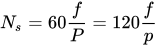
and in rad·s−1, by:
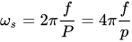
where:

  • is the frequency of the AC supply current in Hz,
  • is the number of magnetic poles,
  • is the number of pole pairs (rarely, planes of commutation), .

Examples

[edit]

A single-phase, 4-pole (2-pole-pair) synchronous motor is operating at an AC supply frequency of 50 Hz. The number of pole-pairs is 2, so the synchronous speed is:

A three-phase, 12-pole (6-pole-pair) synchronous motor is operating at an AC supply frequency of 60 Hz. The number of pole-pairs is 6, so the synchronous speed is:

The number of magnetic poles, , is equal to the number of coil groups per phase. To determine the number of coil groups per phase in a 3-phase motor, count the number of coils, divide by the number of phases, which is 3. The coils may span several slots in the stator core, making it tedious to count them. For a 3-phase motor, if you count a total of 12 coil groups, it has 4 magnetic poles. For a 12-pole 3-phase machine, there will be 36 coils. The number of magnetic poles in the rotor is equal to the number of magnetic poles in the stator.

Construction

[edit]
Rotor of a large water pump. The slip rings can be seen below the rotor drum.
Stator winding of a large water pump

The principal components of electric motors are the stator and the rotor.[26] Synchronous motor and induction motor stators are similar in construction.[27] The construction of synchronous motor is similar to that of an alternator (also called synchronous generator).[28] The stator frame contains wrapper plate (except for wound-rotor synchronous doubly fed electric machines). Circumferential ribs and keybars are attached to the wrapper plate. To carry the weight of the machine, frame mounts and footings are required.[29] The synchronous stator winding consists of a 3 phase winding. It is provided with a 3 phase supply, and the rotor is provided with a DC supply.[citation needed]

DC excited motors require brushes and slip rings to connect to the excitation supply.[30] The field winding can be excited by a brushless exciter.[31] Cylindrical, round rotors, (also known as non-salient pole rotor) are used for up to six poles.

In some machines or when a large number of poles are needed, a salient pole rotor is used.[32][33]

Most synchronous motor construction uses a stationary armature and rotating field winding. This type of construction has an advantage[according to whom?] over DC motor type where the armature used is of rotating type.

Operation

[edit]

Electric motors generate power due to the interaction of the magnetic fields of the stator and the rotor. In synchronous motors, the stator carries 3 phase currents and produces 3 phase rotating magnetic flux (and therefore a rotating magnetic field). The rotor eventually locks in with the rotating magnetic field and rotates along with it. Once the rotor field locks in with the rotating magnetic field, the motor is said to be synched. A single-phase (or two-phase derived from single phase) stator is possible, but in this case the direction of rotation is not defined and the machine may start in either direction unless prevented from doing so by startup arrangements.[34]

Amortisseur winding

[edit]

Once the motor is in operation, the speed of the motor is dependent only on the supply frequency. When the motor load is increased beyond the breakdown load, the motor falls out of synchronization and the rotor no longer follows the rotating magnetic field.

Since the motor cannot produce torque if it falls out of synchronization, practical synchronous motors have a partial or complete squirrel-cage damper called an amortisseur winding to stabilize operation and facilitate starting.

Because this winding is smaller than that of an equivalent induction motor and can overheat on long operation, and because large slip-frequency voltages are induced in the rotor excitation winding, synchronous motor protection devices sense this condition and interrupt the power supply (out of step protection).[34]

Starting methods

[edit]
An early precision electric clock from the 1920s that uses a synchronous motor. The clock must first be started by spinning the main gear by hand.

Above a certain size, synchronous motors cannot self-start. This property is due to rotor inertia; it cannot instantly follow the rotation of the stator's magnetic field. Since a synchronous motor produces no inherent average torque at standstill, it cannot accelerate to synchronous speed without a supplemental mechanism.[3]

Large motors operating on commercial power include a squirrel-cage induction winding that provides sufficient torque for acceleration and also serves to damp motor speed oscillations.[3] Once the rotor nears the synchronous speed, the field winding becomes excited and the motor pulls into synchronization. Very large motor systems may include a "pony" motor that accelerates the unloaded synchronous machine before load is applied.[35][36] Electronically controlled motors can be accelerated from zero speed by changing the frequency of the stator current.[37]

Small synchronous motors are commonly used in line-powered electric mechanical clocks or timers that use the power line frequency to run the gear mechanism at the correct speed. Such small synchronous motors are able to start without assistance if the moment of inertia of the rotor and its mechanical load are sufficiently small. The motor accelerates from slip speed to synchronous speed during an accelerating half cycle of the reluctance torque.[3] Single-phase synchronous motors such as in electric wall clocks can freely rotate in either direction, unlike a shaded-pole type.

Costs are an important parameter for starters.[38] Rotor excitation is a possible way to resolve the issue.[39] In addition, starting methods for large synchronous machines include repetitive polarity inversion of the rotor poles during startup.[40]

Applications, special properties, and advantages

[edit]

Use as synchronous condenser

[edit]
V-curve of a synchronous machine

By varying the excitation of a synchronous motor, it can be made to operate at lagging, leading and unity power factor. Excitation at which the power factor is unity is termed normal excitation voltage.[41] The magnitude of current at this excitation is minimum.[41] Excitation voltage more than normal excitation is called over excitation voltage, excitation voltage less than normal excitation is called under excitation.[41] When the motor is over excited, the back emf will be greater than the motor terminal voltage. This causes a demagnetizing effect due to armature reaction.[42]

The V curve of a synchronous machine shows armature current as a function of field current. With increasing field current armature current at first decreases, then reaches a minimum, then increases. The minimum point is also the point at which power factor is unity.[43]

This ability to selectively control power factor can be exploited for power factor correction of the power system to which the motor is connected. Since most power systems of any significant size have a net lagging power factor, the presence of overexcited synchronous motors moves the system's net power factor closer to unity, improving efficiency. Such power-factor correction is usually a side effect of motors already present in the system to provide mechanical work, although motors can be run without mechanical load simply to provide power-factor correction. In large industrial plants such as factories the interaction between synchronous motors and other, lagging, loads may be an explicit consideration in the plant's electrical design.[citation needed]

Steady-state stability limit

[edit]

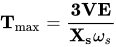
where,

is the torque
is the torque angle
is the maximum torque

here,

When load is applied, torque angle increases. When = 90° the torque will be maximum. If load is applied further then the motor will lose its synchronism, since motor torque will be less than load torque.[44][45] The maximum load torque that can be applied to a motor without losing its synchronism is called steady state stability limit of a synchronous motor.[44]

Other

[edit]

Synchronous motors are especially useful in applications requiring precise speed or position control:

  • Speed is independent of the load over the operating range of the motor.
  • Speed and position may be accurately controlled using open loop controls (e.g. stepper motors).
  • Low-power applications include positioning machines, where high precision is required, and robot actuators.
  • They will hold their position when a DC current is applied to both the stator and the rotor windings.
  • A clock driven by a synchronous motor is in principle as accurate as the line frequency of its power source. (Although small frequency drifts will occur over any given several hours, grid operators actively adjust line frequency in later periods to compensate, thereby keeping motor-driven clocks accurate; see Utility frequency § Stability.)
  • Record player turntables
  • Increased efficiency in low-speed applications (e.g. ball mills).

Subtypes

[edit]

See also

[edit]

References

[edit]

Sources

[edit]
[edit]
Revisions and contributorsEdit on WikipediaRead on Wikipedia
from Grokipedia
A synchronous motor is an alternating current (AC) electric motor in which, at steady state, the rotation of the shaft is synchronized with the frequency of the supply current, causing the rotor to turn at a constant speed known as the synchronous speed.[1] This synchronization occurs because the rotor's magnetic field locks with the rotating magnetic field produced by the stator windings, eliminating any slip between the rotor and the stator field, unlike in asynchronous induction motors.[2] The synchronous speed is determined by the formula $ n_s = \frac{120f}{p} $, where $ f $ is the supply frequency in hertz and $ p $ is the number of poles, ensuring the motor maintains precise speed control regardless of load variations.[3] The basic construction of a synchronous motor resembles that of an induction motor, with a stator featuring polyphase windings that generate a rotating magnetic field when energized by AC power, and a rotor that can be of salient pole or cylindrical design.[4] The rotor is typically excited by direct current (DC) supplied through slip rings to create a constant magnetic field, or it may use permanent magnets in modern variants like permanent magnet synchronous motors (PMSMs).[2] In operation, the stator's rotating field induces a magnetic interaction with the rotor's field, producing torque that aligns and sustains rotation at synchronous speed; however, these motors are not self-starting and require auxiliary methods, such as damper windings or pony motors, to accelerate the rotor to near-synchronous speed before locking in.[5] By adjusting the rotor excitation, the motor can operate at leading, unity, or lagging power factors, making it valuable for power factor correction in industrial systems.[3] Synchronous motors offer several notable advantages, including higher efficiency (often a few percent better than induction motors), constant speed under varying loads, and the ability to improve system power factor when over-excited.[3] They are commonly applied in scenarios requiring precise speed, such as electric vehicles (especially PMSMs for their high power density and efficiency), power generation plants for synchronous condensers, clocks, and industrial drives like compressors and pumps.[2] Despite these benefits, disadvantages include higher initial cost, complexity in starting and control, and the need for DC excitation systems in non-permanent magnet types, which are typically employed in applications where precision justifies the added complexity.[6]

Fundamentals

Definition and Operating Principle

A synchronous motor is an alternating current (AC) electric motor in which, at steady state, the rotation of the rotor is synchronized with the frequency of the supply current, resulting in the rotor speed being exactly equal to the synchronous speed of the rotating magnetic field produced by the stator windings.[7] Unlike induction motors, synchronous motors operate without slip, maintaining a constant speed regardless of load variations within their normal operating limits.[7] This synchronization enables precise speed control and high efficiency, making synchronous motors suitable for applications requiring constant speed, such as in power factor correction and industrial drives. The operating principle of a synchronous motor relies on the interaction between the rotating magnetic field generated by the stator and the magnetic field of the rotor. When three-phase AC currents are supplied to the stator windings, they produce a rotating magnetic field that revolves at synchronous speed. The rotor, equipped with either permanent magnets, electromagnets, or salient poles, develops its own magnetic field, which locks into alignment with the stator's rotating field. This alignment causes the rotor to rotate at the same speed as the stator field, producing torque through electromagnetic attraction between the unlike poles or via reluctance torque in cases without excitation.[8] The rotor-stator field locking ensures that any tendency to slip is counteracted by the restoring torque, maintaining synchronism.[9] Nikola Tesla developed a key advancement in synchronous motors in 1887–1888 with a brushless polyphase design utilizing a rotating magnetic field to achieve uniform speed independent of load, building on earlier synchronous motor concepts.[10] This innovation was detailed in U.S. Patent 381,968, filed on October 12, 1887, and issued on May 1, 1888, employing multiple independent circuits with phased alternating currents to create the progressive shifting of magnetism, eliminating the need for commutators.[10][11] The torque production in a synchronous motor is governed by the equation:
T=3VEfωsXssinδ T = \frac{3 V E_f }{ \omega_s X_s } \sin \delta
where $ T $ is the electromagnetic torque, $ \omega_s $ is the synchronous angular speed, $ V $ is the terminal voltage per phase, $ E_f $ is the excitation voltage (induced EMF in the stator due to rotor field), $ X_s $ is the synchronous reactance per phase, and $ \delta $ is the load angle (torque angle) between the rotor field and the resultant air-gap field.[12] This equation shows that torque is proportional to the sine of the load angle, reaching a maximum at $ \delta = 90^\circ $, beyond which the motor risks losing synchronism if the load exceeds the pull-out torque.[12]

Synchronous Speed

The synchronous speed of a synchronous motor refers to the constant rotational speed of the magnetic field generated by the stator windings, which remains independent of the mechanical load applied to the rotor during steady-state operation. This speed is determined solely by the electrical characteristics of the power supply and the motor's design, ensuring precise and stable performance in applications requiring consistent velocity, such as in power generation or timing devices. Unlike asynchronous motors, where speed varies with load due to slip, the synchronous motor's rotor locks into step with the rotating field, maintaining exact synchronization. The synchronous speed $ n_s $, expressed in revolutions per minute (RPM), is calculated using the formula:
ns=120fp n_s = \frac{120 f}{p}
where $ f $ is the frequency of the AC supply in hertz (Hz), and $ p $ is the total number of magnetic poles in the motor. This equation arises from the relationship between the frequency of the alternating current, which induces the rotating field, and the spatial arrangement of the poles, with the factor of 120 accounting for the conversion from cycles per second to RPM across a two-pole pair. The primary factors influencing synchronous speed are thus the supply frequency and the number of pole pairs; increasing the number of poles reduces the speed, while higher frequency accelerates it. For instance, a four-pole synchronous motor connected to a standard 60 Hz supply, common in North America, operates at $ n_s = \frac{120 \times 60}{4} = 1800 $ RPM. In contrast, on a 50 Hz grid prevalent in Europe and Asia, the same motor would run at $ n_s = \frac{120 \times 50}{4} = 1500 $ RPM, highlighting a 20% speed difference that affects equipment compatibility across regions. To enable multi-speed operation without changing the motor, pole-changing windings can reconfigure the stator connections to effectively alter the number of poles, allowing discrete speed steps—for example, switching from four to eight poles to halve the speed while maintaining synchronization. In terms of motor performance, the rotor must precisely match the synchronous speed for effective torque production and stable operation; any deviation results in loss of synchronism, and in steady-state conditions, the slip—the difference between synchronous and rotor speeds—is zero, ensuring no relative motion between the rotor field and stator field. This zero-slip characteristic provides inherent speed regulation but requires auxiliary starting mechanisms, as the motor cannot self-start under load from standstill.

Construction

Stator Design

The stator of a synchronous motor serves as the stationary component responsible for generating a rotating magnetic field when supplied with three-phase alternating current. It comprises a cylindrical frame, typically made of cast iron for structural support and protection of internal elements. The core is constructed from thin, insulated laminations of silicon steel, arranged to form a hollow cylinder with slots cut into its inner periphery; these slots house the armature windings. The use of laminations minimizes eddy current and hysteresis losses by interrupting the paths of induced currents in the core material.[13][14] The windings are distributed three-phase coils, usually made of enameled copper for high conductivity and insulation, though aluminum is sometimes used in cost-sensitive applications. These windings are placed in the core slots and connected in a star configuration to produce a balanced, sinusoidal magnetic field upon energization. The distributed nature of the windings across multiple slots per phase ensures a smooth rotating magnetic field with reduced harmonic content, essential for efficient synchronization. Copper windings are preferred due to their lower resistance, which helps in managing the magnetizing current required for field production.[13][15][16] Design variations in the stator accommodate different motor applications, such as high-speed turbo-type machines with cylindrical rotors versus low-speed salient-pole configurations. In high-speed designs, the stator features a smooth bore with narrow, semi-closed slots to minimize reluctance variations and maintain uniform air-gap flux density. For salient-pole motors, wider open slots may be employed to facilitate manufacturing, though this introduces slotting effects that increase the effective air gap and synchronous reactance by altering the magnetic reluctance. The stator's construction is fundamentally similar to that of an induction motor, sharing the laminated core and distributed windings, but it is optimized for synchronous operation through a larger air gap and higher reactance to better handle the interaction with a DC-excited rotor field.[15][17][18]

Rotor Configurations

The rotor of a synchronous motor is designed to produce a magnetic field that locks in synchronism with the rotating magnetic field generated by the stator, enabling constant-speed operation. Two primary configurations exist: salient-pole and cylindrical (or non-salient) rotors, distinguished by their geometry and application suitability. Salient-pole rotors feature projecting poles that create a non-uniform air gap, typically used in low-speed applications with multiple poles (often 4 or more), such as those driven by hydraulic turbines at speeds of 50-300 rpm.[19] In contrast, cylindrical rotors have a smooth, uniform surface with distributed field windings embedded in slots, suited for high-speed operations with fewer poles (usually 2 or 4), as in steam or gas turbine drives reaching 1800-3600 rpm.[19] These designs ensure the rotor's magnetic field aligns precisely with the stator's for torque production without slip. Constructionally, salient-pole rotors consist of laminated steel pole structures mounted directly on the shaft, with field windings wound around each pole to provide DC excitation, generating fixed north-south poles. The laminations, typically made of high-permeability silicon steel, minimize eddy current losses in the varying magnetic field. Cylindrical rotors, often forged from solid steel for mechanical strength at high speeds, also feature slots for distributed DC-excited field windings, though their uniform shape reduces reluctance variations. Both configurations may include amortisseur (damper) windings—such as copper bars in salient-pole faces or inherent eddy current paths in cylindrical rotors—for damping oscillations and aiding starting in larger machines, but these do not contribute to steady-state torque.[19] Unlike induction motor rotors, which rely on induced AC currents in shorted windings or bars to produce a rotating field and allow slip, synchronous motor rotors incorporate a DC field source (via windings or other means) to establish fixed magnetic poles that maintain exact synchronism with the stator field, eliminating slip under load. This fundamental difference enables synchronous motors to operate at precisely the synchronous speed determined by supply frequency and pole count, with the rotor mounted coaxially on the shaft for direct mechanical coupling to the load.[19]

Types

Permanent Magnet Synchronous Motors

Permanent magnet synchronous motors (PMSMs) utilize permanent magnets embedded in the rotor to generate the magnetic field, eliminating the need for external excitation systems. The rotor configurations typically involve either surface-mounted permanent magnets (SPM), where magnets are attached directly to the rotor surface, or interior permanent magnets (IPM), where magnets are embedded within the rotor core to enhance mechanical robustness and reluctance torque. Since the 1980s, high-performance rare-earth magnets such as neodymium-iron-boron (NdFeB) have been widely adopted due to their superior magnetic properties, enabling higher flux densities and more compact designs.[20][21] These motors offer significant advantages, including high efficiency levels reaching up to 95%, attributed to the absence of rotor copper losses and minimal excitation requirements. Unlike wound-field designs, PMSMs require no slip rings or brushes, reducing maintenance needs and improving reliability in harsh environments. Their compact size and high power density make them suitable for space-constrained applications, while the self-excited rotor field ensures constant-speed operation synchronized with the stator's rotating magnetic field.[22][23][24] In operation, the permanent magnets produce a constant flux linkage, generating a back electromotive force (back-EMF) in the stator windings proportional to the rotor speed. This back-EMF is expressed as $ E = k \omega \Phi $, where $ E $ is the back-EMF magnitude, $ k $ is a machine constant, $ \omega $ is the angular speed, and $ \Phi $ is the magnetic flux per pole. The self-sustaining field allows for precise torque control without additional power input to the rotor, enhancing overall system efficiency. In modern applications, PMSMs are extensively used in electric vehicles (EVs) for propulsion due to their high torque-to-weight ratio and regenerative braking capabilities, as well as in renewable energy systems like wind turbines for efficient power generation. However, exposure to high temperatures can pose risks of demagnetization in NdFeB magnets, potentially reducing flux and performance, necessitating thermal management strategies such as cooling systems.[25][26][27]

Reluctance Synchronous Motors

Reluctance synchronous motors generate torque through the variation in magnetic reluctance along different paths in the rotor, caused by its saliency. Unlike other synchronous motors, they rely solely on the geometric design of the rotor to produce reluctance torque, without the need for permanent magnets or rotor windings. The fundamental principle stems from the rotor's tendency to align its low-reluctance axis with the stator's rotating magnetic field, minimizing the magnetic circuit's reluctance. This alignment produces a torque that maintains synchronous operation once achieved. The torque $ T $ in a reluctance motor can be mathematically expressed as
T=12i2dLdθ, T = \frac{1}{2} i^2 \frac{dL}{d\theta},
where $ i $ is the phase current, $ L $ is the phase inductance, and $ \theta $ is the rotor angular position; this equation highlights how torque arises from the rate of change of inductance with rotor position.[28] The rotor design in synchronous reluctance motors (SynRMs) emphasizes magnetic saliency through salient poles or layered structures with flux barriers, creating unequal air gaps between the direct (d-) and quadrature (q-) axes. In salient-pole rotors, projections of ferromagnetic material alternate with larger air gaps, providing a clear path for flux along the d-axis while increasing reluctance along the q-axis. More advanced designs use transversely laminated rotors with multiple flux barriers per pole to enhance saliency ratio and reduce torque ripple. This contrasts with switched reluctance motors (SRMs), which also exploit variable reluctance but operate via sequential switching of stator phases for stepped motion, lacking inherent synchronism with an AC supply and typically used in stepper or variable-speed applications without fixed pole alignment.[29] SynRMs offer several advantages, including a simple and robust construction due to the absence of rotor magnets or excitation windings, which reduces material costs and improves reliability in harsh environments. Their lack of rotor copper losses contributes to high efficiency, often reaching 90-95% in variable-speed drives when paired with vector control inverters, surpassing traditional induction motors in energy savings for constant-torque applications. Additionally, the design avoids rare-earth materials, mitigating supply chain vulnerabilities associated with permanent magnets. These motors exhibit good power factor at high loads and low maintenance needs, though they may require careful starting mechanisms to achieve pull-in synchronism.[30][31] Applications of SynRMs are prominent in low-cost, efficiency-focused scenarios such as pumps, fans, and compressors in industrial and HVAC systems, where their synchronous speed control ensures precise operation without slippage. Post-2010 advancements have integrated hybrid permanent magnet-assisted SynRMs (PMaSynRMs) in electric vehicles (EVs), combining reluctance torque with minimal rare-earth magnets to achieve high torque density and efficiency over wide speed ranges, as seen in traction motors for passenger cars and commercial fleets. These hybrids leverage the reluctance component for cost reduction while enhancing overall performance in automotive powertrains.[31][32]

Hysteresis Synchronous Motors

Hysteresis synchronous motors generate torque through the magnetic hysteresis effect in the rotor material, where the magnetization lags behind the applied magnetic field produced by the stator, creating a rotational force that aligns the rotor with the rotating field. This lag angle remains constant regardless of speed, resulting in a uniform torque from standstill to synchronous speed. The hysteresis torque arises from the energy dissipated in traversing the B-H hysteresis loop, and it can be approximated by the formula
T=ηBmax2V2μ0g, T = \frac{\eta B_{\max}^2 V}{2 \mu_0 g},
where η\eta is the hysteresis coefficient (related to the Steinmetz constant), BmaxB_{\max} is the maximum flux density, VV is the rotor volume, μ0\mu_0 is the permeability of free space, and gg is the air gap length.[33] The rotor in a hysteresis synchronous motor is a smooth, cylindrical structure constructed from hard magnetic materials exhibiting high coercivity and retentivity, such as chrome steel or cobalt-iron alloys, without any windings, slots, or salient poles. This design ensures a uniform magnetic response across the rotor surface, promoting smooth acceleration and minimal vibration during operation.[33][34] These motors are inherently self-starting due to the sustained hysteresis torque that accelerates the rotor to synchronous speed without additional mechanisms, maintaining a precise constant speed once synchronized. The pull-out torque, which represents the maximum load the motor can handle before losing synchronism, is notably independent of operating speed, providing reliable performance under varying loads up to the pull-out point. However, their efficiency is limited by inherent hysteresis and eddy current losses, restricting practical power ratings to below 1 kW.[33][35] Hysteresis synchronous motors find primary use in low-power, precision applications requiring quiet, vibration-free operation and exact speed control, such as timing devices, electric clocks, and turntables in record players. Developed in the 1930s through foundational theoretical work on torque production, they continue to serve in modern precision instruments where compactness and reliability outweigh efficiency concerns.[36][35]

Wound-Field Synchronous Motors

Wound-field synchronous motors feature a rotor constructed with salient poles that carry concentrated DC field windings, typically made of copper coils wound around the pole cores to produce a magnetic field when excited. These rotors require direct current supplied via slip rings and carbon brushes mounted on the rotor shaft, allowing electrical connection to a stationary excitation source while the rotor rotates. This configuration is particularly suited for low-speed, high-torque applications due to the robust mechanical structure of the salient poles, which support the windings under centrifugal forces.[37][38] Excitation in wound-field synchronous motors can be achieved through a separate stationary DC supply connected via the slip rings and brushes, a method prevalent from the 1920s to the 1960s, or via brushless systems employing rotating rectifiers mounted on the rotor shaft. In brushless designs, an AC exciter on the rotor provides alternating current that is converted to DC by silicon-controlled rectifiers, eliminating the need for slip rings and reducing maintenance; these systems became commercially viable in the 1960s with the advent of solid-state rectifiers. The field current IfI_f supplied to the rotor windings determines the flux Φ\Phi per pole, which in turn governs the internal generated electromotive force (EMF) EfE_f according to the equation Ef=4.44fNΦE_f = 4.44 f N \Phi, where ff is the supply frequency and NN is the number of turns per phase in the stator winding.[16][39] The primary advantages of wound-field synchronous motors include the ability to adjust the power factor by varying the field excitation—overexcitation leads to leading power factor operation for compensation, while underexcitation enables lagging operation—making them ideal for improving system efficiency in industrial and utility settings. Additionally, their controllable excitation provides high stability in large-scale power generation, allowing rapid response to grid disturbances through automatic voltage regulators that modulate field current for reactive power support and transient stability. In modern applications, brushless wound-field designs dominate due to their reliability and low maintenance, and they are widely used in hydroelectric generators where low-speed salient-pole rotors match the turbine's operational requirements.[16][40][41]

Operation

Synchronization Process

The synchronization process in a synchronous motor requires the rotor to reach a speed sufficiently close to the synchronous speed, typically 95-98% of it, before the DC excitation is applied to the rotor field winding. This excitation creates a fixed magnetic pole structure on the rotor, which interacts with the rotating magnetic field produced by the stator windings. The resulting electromagnetic torque, known as the pull-in torque, acts to align the rotor poles with the stator's rotating field, pulling the rotor into synchronism. This alignment occurs dynamically as the rotor "locks" into step, ensuring the rotor rotates at exactly the synchronous speed determined by the supply frequency and number of poles.[16] Central to maintaining this lock is the load angle δ, defined as the angular displacement between the rotor's magnetic axis and the stator's rotating field axis. Under no-load conditions, δ approaches zero, but as load increases, δ rises to produce the necessary torque, reaching a maximum of 90° at the point of maximum torque capability. For stable operation, δ must remain less than 90°; beyond this, the motor risks losing synchronism and slipping poles. This angle directly influences the synchronizing torque, which restores alignment if minor disturbances occur.[42][43] During the transition to synchronism, the rotor undergoes transient oscillations around its equilibrium position due to inertia and varying torque pulses. These oscillations, if undamped, can lead to hunting—prolonged back-and-forth swinging that may prevent stable locking. Damping is achieved through the interaction of induced currents in the rotor's damper windings or the load itself, which dissipate energy and attenuate the oscillations over time, allowing the rotor to settle into steady alignment. The effectiveness of this damping determines the motor's ability to synchronize under varying inertia loads.[43][3] Once synchronization is achieved, the motor maintains a constant rotor speed equal to the synchronous speed, exhibiting zero slip regardless of load changes within the stable operating range. This locked-step operation distinguishes synchronous motors from induction types, enabling precise speed control tied directly to the power supply frequency.[16][42]

Amortisseur Windings

Amortisseur windings, also known as damper windings, consist of copper or brass bars embedded in slots on the faces of the salient rotor poles of a synchronous motor, connected at both ends by short-circuiting rings to form a squirrel-cage structure.[44][16] This design allows the windings to function similarly to the rotor cage in an induction motor, where induced currents flow in response to relative motion between the rotor and the rotating magnetic field.[45] These windings serve multiple critical functions during motor operation. They provide starting torque by generating induction-like torque that accelerates the rotor from standstill to near-synchronous speed, typically delivering 40% to 200% of full-load torque depending on the design.[16] Additionally, they dampen rotor oscillations caused by load fluctuations or disturbances, producing opposing torques that counteract deviations from synchronous speed and thereby enhance sub-transient stability.[44] By minimizing these oscillations, known as hunting, the windings ensure stable synchronization and prevent loss of synchronism under transient conditions.[45] Amortisseur windings provide self-starting capability and damping of oscillations, which are important for reliable performance in industrial applications.[44]

Steady-State Performance

In steady-state operation, a synchronous motor runs at constant synchronous speed with balanced sinusoidal voltages and currents, where the rotor field locks with the stator's rotating magnetic field at a load angle δ.[https://www.engr.siu.edu/staff2/spezia/Web332b/Lecture%20Notes/Lesson%2017_et332b.pdf] The per-phase equivalent circuit simplifies to the terminal voltage phasor V equaling the excitation electromotive force (EMF) phasor E_f plus the voltage drop across the armature impedance, expressed as:
V=Ef+Ia(Ra+jXs) \mathbf{V} = \mathbf{E}_f + \mathbf{I}_a (R_a + j X_s)
where I_a is the armature current phasor, R_a is the armature resistance (often negligible for analysis), and X_s is the synchronous reactance.[https://www.engr.siu.edu/staff2/spezia/Web332b/Lecture%20Notes/Lesson%2017_et332b.pdf] This phasor diagram illustrates the vector relationships, with δ representing the angle between V and E_f; for motoring, δ is negative, indicating E_f lags V.[https://home.engineering.iastate.edu/~jdm/OldClasses/ee303_spring2019/EE.PSE.G1.pdf] Neglecting R_a, the diagram shows I_a decomposed into components in phase and quadrature with V, enabling analysis of active and reactive power flows. The developed electromagnetic power for a three-phase synchronous motor is given by:
P=3VEfXssinδ P = \frac{3 V E_f}{X_s} \sin \delta
where V and E_f are phase magnitudes.[https://www.engr.siu.edu/staff2/spezia/Web332b/Lecture%20Notes/Lesson%2017_et332b.pdf] This expression highlights that power is maximized when δ = 90°, corresponding to the stability limit beyond which the motor risks losing synchronism if load torque increases further.[https://dspace.mit.edu/bitstream/handle/1721.1/85612/6-685-fall-2005/contents/lecture-notes/chapter4.pdf] The pull-out torque, or maximum torque T_po before desynchronization, occurs at this angle and is:
Tpo=3VEfωsXs T_{po} = \frac{3 V E_f}{\omega_s X_s}
with ω_s as the synchronous angular speed; this torque scales with excitation level E_f, typically 2–3 times the full-load torque for practical designs.[http://www.rakov.ece.ufl.edu/teaching/3211/Packet/5_Synchronous.pdf] Power factor in steady-state operation is controlled by adjusting the field excitation current, which varies E_f relative to V.[https://www.maec.msu.edu/application/files/8316/4555/7425/Tech_Note_316_Synchronous_Motors.pdf] Under-excitation (E_f < V) results in a lagging power factor, as the motor draws inductive reactive power; normal excitation (E_f ≈ V) yields unity power factor; and over-excitation (E_f > V) produces a leading power factor, allowing the motor to supply capacitive reactive power for system correction.[https://do-server1.sfs.uwm.edu/find/8D9337489W/ppt/7D1813W/induction_and-synchronous_machines.pdf] This capability makes synchronous motors valuable for improving overall power factor in industrial settings with inductive loads. Efficiency η in steady-state is defined as the ratio of mechanical output power P_out to total input power:
η=PoutPout+Pcu+Pfe+Pmech \eta = \frac{P_{out}}{P_{out} + P_{cu} + P_{fe} + P_{mech}}
where P_cu are copper losses (I_a² R_a in armature and field windings), P_fe are iron losses (hysteresis and eddy currents in the core, dependent on flux density and frequency), and P_mech are mechanical losses (friction and windage, roughly constant at synchronous speed).[https://chrismi.sdsu.edu/publications/2005_20_1_IEEE_TEC_Minimization.pdf] Synchronous motors typically achieve efficiencies of 90–98% at rated load, with copper losses dominating under high current and iron losses minimized by laminated cores; optimization involves balancing excitation to reduce I_a while maintaining torque.[https://www.engr.siu.edu/staff2/spezia/Web332b/Lecture%20Notes/Lesson%2018_et332b.pdf]

Starting Methods

Self-Starting Techniques

Synchronous motors are not inherently self-starting due to the fixed rotor field that does not produce a rotating torque from a stationary position when energized with AC supply.[42] To overcome this, self-starting techniques rely on auxiliary mechanisms or material properties that generate initial torque. One common method involves using amortisseur windings, also known as damper or squirrel-cage windings embedded in the rotor poles, which function similarly to those in induction motors.[16] During startup, the stator's rotating magnetic field induces currents in these short-circuited windings, producing an induction torque that accelerates the rotor toward synchronous speed with fractional slip.[46] The field winding is short-circuited or unenergized initially to avoid opposition, and DC excitation is applied once the rotor reaches approximately 95% of synchronous speed, allowing pull-in via reluctance or synchronous torque.[42][16] Permanent magnet synchronous motors (PMSMs) can often self-start without additional windings, relying on the permanent magnet rotor field interacting with the stator's rotating magnetic field, enhanced by reluctance torque in designs with buried magnets.[47] Another self-starting approach uses a pony motor, a small auxiliary induction motor mounted on the main rotor shaft to bring it up to near-synchronous speed before disengaging and applying field excitation.[48] This method is particularly suited for applications where the main motor's amortisseur windings provide insufficient starting torque. Hysteresis synchronous motors achieve inherent self-starting through the hysteresis effect in the rotor material, typically a high-coercivity alloy like cobalt steel, which produces a constant torque during acceleration independent of slip.[33] The torque arises from the lagging magnetization curve, enabling smooth startup without additional windings, though efficiency is lower at synchronous speed.[49] Reluctance synchronous motors can also exhibit inherent self-starting in certain designs due to the saliency-induced torque curve, where the rotor aligns with the stator field via variable reluctance paths, providing average positive torque over a cycle despite oscillatory components. However, for reliable operation, many incorporate amortisseur windings to augment induction torque during initial acceleration. These techniques are effective but face limitations in very large motors or applications with high rotor inertia, where rapid acceleration to the required 95% speed is challenging, risking overheating in amortisseur windings or prolonged starting times.[42][16] In such cases, the rotor's inability to respond quickly to the reversing fields results in negligible net torque without external assistance.[42]

Auxiliary Starting Devices

For large synchronous motors, particularly wound-field types, auxiliary starting devices are essential because the motors lack sufficient inherent torque to achieve synchronization from standstill without external assistance. These devices enable controlled acceleration of the rotor to near synchronous speed, typically 95-98% of rated speed, before applying direct current (DC) field excitation to the rotor windings, allowing the motor to pull into step with the stator's rotating magnetic field.[50] This approach minimizes electrical stress, inrush currents, and mechanical wear compared to direct-on-line starting.[51] One common auxiliary device is the pony motor, an external prime mover—often a DC or smaller AC induction motor—mechanically coupled to the synchronous motor's shaft. The pony motor accelerates the rotor gradually to 95-98% of synchronous speed under no-load or light-load conditions, after which the stator power is applied and DC excitation is introduced to achieve synchronization. This method is particularly suitable for very large motors in applications with weak power systems, where full-voltage starting would cause excessive voltage dips.[43] For example, in a 25 MW synchronous motor driving a compressor, a pony motor provides reliable acceleration without relying on costly high-power inverters.[52] Variable frequency drives (VFDs), also known as inverters, represent another key auxiliary starting mechanism, supplying adjustable voltage and frequency to the stator windings for a soft, controlled ramp-up. In weak power systems, a pulse-width modulated (PWM) VFD rated at only 25% of the motor's horsepower can successfully start an unloaded large synchronous motor by gradually increasing frequency to match rotor speed, reducing starting current to 150-200% of full-load amperes and limiting voltage drops to under 10%.[51] Once near synchronous speed is reached, the VFD transitions to field excitation application, often bypassing to direct line power for efficiency. Since the early 2000s, inverter-fed starting has become widespread for energy savings and precise torque control in industrial drives exceeding 1,000 kW, supplanting older methods in many installations.[16] Brushless exciters serve as an integrated auxiliary device that combines rotor excitation with starting support, eliminating slip rings and brushes for maintenance-free operation. These systems use a rotating rectifier on the rotor shaft, powered by an auxiliary AC exciter winding, to generate and apply DC field current precisely when the motor reaches pull-in speed (typically 95% synchronous). In brushless setups, the synchronous motor first accelerates via amortisseur windings or an external aid like a VFD, then the exciter automatically sequences field application to lock the rotor into synchronism, enhancing reliability in high-power applications up to 10,000 HP.[16] The standard procedure for applying field excitation in these auxiliary methods involves monitoring rotor speed via sensors or induced voltage frequency, which drops to about 3 Hz at 95% speed. At this point, the field contactor closes to supply DC (often 100-300 V), pulling the rotor into synchronism within seconds while measuring parameters like field discharge resistance (typically 1 ohm) and acceleration time (e.g., 1-2 seconds for a 1,000 HP motor). This sequenced approach ensures stable starting and protects against out-of-step conditions.[50]

Control Techniques

Scalar Control Methods

Scalar control methods for synchronous motors, such as permanent magnet synchronous motors (PMSMs) and wound-field synchronous motors, rely on basic adjustments to the stator voltage and frequency to achieve speed and torque regulation without requiring complex feedback mechanisms. These techniques are particularly valued for their simplicity and low computational demands in drive systems.[53][54] The predominant scalar control strategy is V/f control, an open-loop method that maintains constant air-gap flux by scaling the supply voltage proportionally to the frequency. In this approach, the frequency determines the synchronous speed, while the voltage adjustment prevents flux saturation or weakening across varying speeds. The flux is approximated by the relation ΦVf\Phi \approx \frac{V}{f}, ensuring stable operation under steady conditions.[53][55] Despite its ease of implementation, V/f control suffers from limitations, including poor dynamic response to load disturbances and suitability only for steady-state operations, as it does not decouple torque and flux components for transient performance. This makes it less ideal for applications demanding rapid acceleration or precise torque control. V/f control finds applications in drives with constant torque loads, such as fans, pumps, and multiple-motor systems in textile or paper mills, where steady speed regulation suffices without high dynamic requirements.[56][57]

Vector and Field-Oriented Control

Vector and field-oriented control (FOC), also known as vector control, enables precise and independent regulation of torque and magnetic flux in synchronous motors by transforming the three-phase stator currents from the stationary abc reference frame to the rotating dq reference frame aligned with the rotor flux. This transformation, known as the Park transformation, decouples the direct (d-axis) and quadrature (q-axis) current components, where the d-axis current idi_d primarily controls the flux magnitude and the q-axis current iqi_q controls the torque production, mimicking the behavior of a separately excited DC motor. The principle was originally formulated for AC machines, including synchronous types, to achieve high dynamic performance through this orthogonal decomposition.[58] In permanent magnet synchronous motors (PMSMs), the electromagnetic torque TeT_e in the dq frame is given by the equation:
Te=32p(λmiq+(LdLq)idiq) T_e = \frac{3}{2} p \left( \lambda_m i_q + (L_d - L_q) i_d i_q \right)
where pp is the number of pole pairs, λm\lambda_m is the permanent magnet flux linkage, LdL_d and LqL_q are the d- and q-axis inductances, respectively; for surface-mounted PMSMs where Ld=LqL_d = L_q, the equation simplifies to Te=32pλmiqT_e = \frac{3}{2} p \lambda_m i_q, emphasizing direct torque proportionality to iqi_q. The control structure employs inner current loops with proportional-integral (PI) regulators to track idi_d^* (often set to zero for maximum torque per ampere) and iqi_q^* references derived from outer speed or position loops, followed by inverse Park transformation to generate voltage commands.[59] Implementation typically integrates space vector pulse-width modulation (SVPWM) to synthesize the required voltages from the inverter, optimizing DC bus utilization and minimizing harmonic distortion compared to sinusoidal PWM. Rotor position feedback is essential for accurate dq transformation and can be obtained using encoders or resolvers for high-precision applications; alternatively, sensorless methods employ observers such as sliding-mode or extended Kalman filters to estimate position and speed from back-EMF measurements, enabling cost-effective operation at speeds above a few percent of rated value.[60][61] The advantages of FOC include excellent dynamic response with fast torque transients, precise speed regulation, and efficiency optimization, making it ideal for servo applications in robotics, electric vehicles, and industrial drives where AC drive-like performance is required without mechanical commutation.[58]

Direct Torque Control

Direct Torque Control (DTC) is a control strategy for synchronous motors, particularly permanent magnet synchronous motors (PMSMs), that directly regulates stator flux and electromagnetic torque without the need for coordinate transformations or current regulators, using hysteresis comparators and switching tables to select appropriate inverter voltage vectors.[62] The method operates in the stator reference frame, where flux and torque errors are compared against hysteresis bands, and a lookup table determines the optimal switching state among the six active and two zero voltage vectors of a voltage source inverter to maintain the flux and torque within their bands.[63] This approach enables sensorless operation by estimating rotor position from stator variables, making it suitable for high-dynamic applications.[62] The core of DTC relies on estimators derived from the motor's voltage model. The stator flux linkage is estimated as
ψs=(vsRsis)dt \boldsymbol{\psi}_s = \int \left( \mathbf{v}_s - R_s \mathbf{i}_s \right) dt
where ψs\boldsymbol{\psi}_s is the stator flux vector, vs\mathbf{v}_s is the stator voltage vector, RsR_s is the stator resistance, and is\mathbf{i}_s is the stator current vector.[64] The electromagnetic torque is then computed from the estimated flux and current as
Te=3P2(ψαiβψβiα) T_e = \frac{3P}{2} \left( \psi_{\alpha} i_{\beta} - \psi_{\beta} i_{\alpha} \right)
with PP denoting the number of pole pairs and α,β\alpha, \beta the stationary frame components.[65] These estimators provide real-time feedback for the control loop, supporting position estimation through the flux angle.[63] DTC offers several advantages, including a simple structure with reduced computational demands due to the absence of pulse-width modulation or proportional-integral regulators, leading to a fast torque response on the order of milliseconds.[62] It exhibits lower sensitivity to motor parameter variations compared to field-oriented control and facilitates sensorless implementation, minimizing hardware requirements.[63] These features make DTC particularly effective in the field-weakening region for high-speed operations.[62] However, conventional DTC suffers from drawbacks such as significant torque and flux ripples caused by the discrete voltage vector selection and variable switching frequency, which can lead to acoustic noise and increased losses.[63] To mitigate these issues, space vector modulation-based DTC (SVM-DTC) has been developed since the 2010s, employing predictive vector synthesis to achieve constant switching frequency and reduce ripple by up to 50% in steady-state operation.[66] DTC finds applications in high-performance drives requiring rapid torque response, such as electric vehicles and industrial servo systems, where its sensorless capabilities enhance reliability and cost-effectiveness.[67]

Applications and Advantages

Industrial and Drive Applications

Synchronous motors find extensive use in industrial settings where constant speed operation is essential, such as driving large compressors in chemical and petrochemical plants, ball mills in mining and cement production, and precision mechanisms in robotics for servo applications.[68][69] These motors maintain exact synchronous speeds determined by the supply frequency, making them ideal for processes requiring stable rotational velocities without slip, as seen in grinding mills and blowers.[16] In robotics, permanent magnet synchronous motors (PMSMs) provide high torque density and responsive control for articulated joints and positioning systems.[70] Permanent magnet variants of synchronous motors are particularly prominent in electric vehicle (EV) propulsion systems, offering compact designs with superior power-to-weight ratios. For instance, Tesla employs PMSMs in models like the Model 3, where the rear drive unit uses an embedded permanent magnet configuration to achieve high efficiency and performance from a 75 kWh battery pack comparable to larger systems.[71][72] This application leverages the motors' ability to deliver precise torque control, often integrated with vector control techniques for variable-speed demands in automotive drives.[73] The advantages of synchronous motors in industrial and drive applications include precise speed regulation at synchronous values, which ensures consistent output in constant-speed operations like pumps and fans, and high overall efficiency due to unity or leading power factor operation that minimizes energy losses.[16] In constant-speed scenarios, they outperform induction motors by avoiding rotor losses from slip, achieving efficiencies often exceeding 95% in large-scale installations.[74] with the global market valued at USD 24.87 billion in 2025.[74] A notable case is in the cement industry, where synchronous motors power grinding mill drives and serve dual roles as synchronous condensers to supply leading reactive power (VARs), improving plant power factor and reducing utility penalties.[75] For example, large synchronous motors on ball mills in cement plants operate at no mechanical load during over-excited modes to act as condensers, stabilizing voltage and enhancing grid efficiency without additional equipment.[76] This integration supports the industry's high-power demands while promoting sustainability through better electrical balance.[77]

Power System Uses

Synchronous condensers are overexcited synchronous motors operated without a mechanical load, primarily to supply reactive power (VARs) to electrical grids and improve power factor. By running unloaded and adjusting the field excitation, these devices draw leading current from the system, compensating for the lagging reactive power demands of inductive loads such as transmission lines and motors. This capability enhances overall system efficiency and reduces losses in power delivery.[78] In operation, synchronous condensers can both generate and absorb reactive power by varying the rotor excitation and load angle (δ), which allows precise control to maintain voltage stability and dampen power oscillations. Overexcitation enables them to supply leading VARs, supporting grid voltage during high-demand periods, while underexcitation permits absorption of excess reactive power to prevent overvoltages. This dynamic response contributes to system inertia and short-circuit strength, particularly in grids with long transmission lines or weak interconnections. Their overload capacity, often 2–2.5 times rated for short durations, further aids in transient stability.[78][79] Historically, synchronous condensers have been employed in power systems since the 1930s to provide reactive compensation and voltage support, predating modern power electronics like STATCOMs. They gained prominence in the mid-20th century for stabilizing large interconnected grids but saw reduced use with the advent of flexible AC transmission systems (FACTS). In contemporary applications, they are integrated into high-voltage direct current (HVDC) links to boost short-circuit ratios and dynamic reactive power, ensuring reliable operation across asynchronous networks.[80][79] A key advantage in modern grids is their role in supporting renewable energy integration through retrofits, such as converting retired fossil fuel plants into synchronous condensers to provide essential inertia and voltage regulation amid increasing wind and solar penetration. These units can operate at leading power factors up to 0.9, offering seamless power factor correction without the switching transients of capacitor banks. This resurgence addresses the decline in rotating mass from conventional generators, enhancing grid resilience in low-inertia environments.[81][82]

Efficiency and Special Properties

Synchronous motors exhibit high efficiency, typically ranging from 94% to 98% at full load, surpassing many induction motors due to their design that minimizes energy dissipation.[83] This superior performance stems from the absence of rotor copper losses, as the rotor receives DC excitation or uses permanent magnets, preventing AC-induced currents that cause I²R losses in induction motor rotors.[84] Consequently, total losses in synchronous motors are reduced by 2-5 percentage points compared to premium induction motors across a wide load range, enhancing overall system energy utilization.[83] A distinctive property of synchronous motors is their ability to operate at unity power factor through precise control of field excitation, which aligns the motor's input current with the voltage phase, thereby eliminating reactive power demands and optimizing electrical network performance.[85] They also enable bidirectional power flow, functioning seamlessly in both motoring and generating modes, which supports energy recovery in dynamic applications like regenerative braking.[86] Certain variants, such as reluctance types, deliver high starting torque while maintaining these operational characteristics.[87] The constant speed operation of synchronous motors, locked precisely to the supply frequency without slip, provides inherent advantages for applications requiring accurate timing and uniform output, resulting in improved product quality and process reliability.[16] However, these benefits come with drawbacks, including the need for a dedicated excitation system that elevates manufacturing and maintenance costs, and complex starting procedures that often rely on external aids due to the motors' non-self-starting nature.[16] Post-2020 advancements, such as the adoption of IE5 ultra-premium efficiency standards for synchronous reluctance motors, have further elevated their performance, achieving loss reductions of up to 30% over IE3 levels and positioning them as key components in green energy initiatives like renewable integration and electrification.

References

User Avatar
No comments yet.