Hubbry Logo
Radio clockRadio clockMain
Open search
Radio clock
Community hub
Radio clock
logo
8 pages, 0 posts
0 subscribers
Be the first to start a discussion here.
Radio clock
Radio clock
from Wikipedia
A modern LF radio-controlled clock

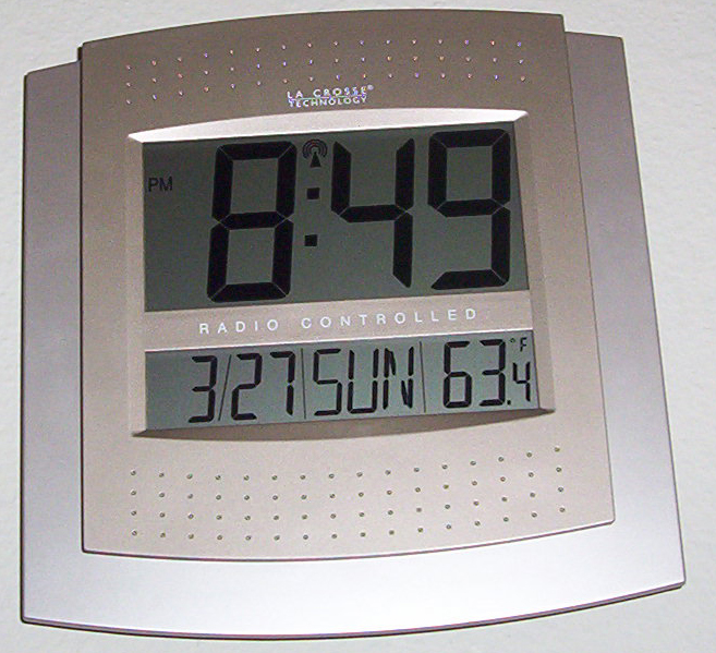
A radio clock or radio-controlled clock (RCC), and often colloquially (and incorrectly[1]) referred to as an "atomic clock", is a type of quartz clock or watch that is automatically synchronized to a time code transmitted by a radio transmitter connected to a time standard such as an atomic clock. Such a clock may be synchronized to the time sent by a single transmitter, such as many national or regional time transmitters, or may use the multiple transmitters used by satellite navigation systems such as Global Positioning System. Such systems may be used to automatically set clocks or for any purpose where accurate time is needed. Radio clocks may include any feature available for a clock, such as alarm function, display of ambient temperature and humidity, broadcast radio reception, etc.

One common style of radio-controlled clock uses time signals transmitted by dedicated terrestrial longwave radio transmitters, which emit a time code that can be demodulated and displayed by the radio controlled clock. The radio controlled clock will contain an accurate time base oscillator to maintain timekeeping if the radio signal is momentarily unavailable. Other radio controlled clocks use the time signals transmitted by dedicated transmitters in the shortwave bands. Systems using dedicated time signal stations can achieve accuracy of a few tens of milliseconds.

GPS satellite receivers also internally generate accurate time information from the satellite signals. Dedicated GPS timing receivers are accurate to better than 1 microsecond; however, general-purpose or consumer grade GPS may have an offset of up to one second between the internally calculated time, which is much more accurate than 1 second, and the time displayed on the screen.

Other broadcast services may include timekeeping information of varying accuracy within their signals. Timepieces with Bluetooth radio support, ranging from watches with basic control of functionality via a mobile app to full smartwatches obtain time information from a connected phone, with no need to receive time signal broadcasts.

Single transmitter

[edit]

Radio clocks synchronized to a terrestrial time signal can usually achieve an accuracy within a hundredth of a second relative to the time standard,[1] generally limited by uncertainties and variability in radio propagation. Some timekeepers, particularly watches such as some Casio Wave Ceptors which are more likely than desk clocks to be used when travelling, can synchronise to any one of several different time signals transmitted in different regions.

Longwave and shortwave transmissions

[edit]

Radio clocks depend on coded time signals from radio stations. The stations vary in broadcast frequency, in geographic location, and in how the signal is modulated to identify the current time. In general, each station has its own format for the time code.

List of radio time signal stations

[edit]
List of radio time signal stations
Frequency Callsign Country Authority Location Aerial type Power Remarks
25 kHz RJH69  Belarus
VNIIFTRI
Vileyka
54°27′47″N 26°46′37″E / 54.46306°N 26.77694°E / 54.46306; 26.77694 (RJH69)
Triple umbrella antenna[a] 300 kW This is Beta time signal.[2] The signal is transmitted in non-overlapping time:
02:00–02:20 UTC RAB99
04:00–04:25 UTC RJH86
06:00–06:20 UTC RAB99
07:00–07:25 UTC RJH69
08:00–08:25 UTC RJH90
09:00–09:25 UTC RJH77
10:00–10:25 UTC RJH86
11:00–11:20 UTC RJH63
RJH77  Russia
VNIIFTRI
Arkhangelsk
64°21′29″N 41°33′58″E / 64.35806°N 41.56611°E / 64.35806; 41.56611 (RJH77)
Triple umbrella antenna[b] 300 kW
RJH63  Russia
VNIIFTRI
Krasnodar
44°46′25″N 39°32′50″E / 44.77361°N 39.54722°E / 44.77361; 39.54722 (RJH63)
Umbrella antenna[c] 300 kW
RJH90  Russia
VNIIFTRI
Nizhny Novgorod
56°10′20″N 43°55′38″E / 56.17222°N 43.92722°E / 56.17222; 43.92722 (RJH90)
Triple umbrella antenna[d] 300 kW
RJH86[2][e]  Kyrgyzstan
VNIIFTRI
Bishkek
43°02′29″N 73°37′09″E / 43.04139°N 73.61917°E / 43.04139; 73.61917 (RJH86)
Triple umbrella antenna[f] 300 kW
RAB99  Russia
VNIIFTRI
Khabarovsk
48°29′29″N 134°48′59″E / 48.49139°N 134.81639°E / 48.49139; 134.81639 (RAB99)
Umbrella antenna[g] 300 kW
40 kHz JJY  Japan
NICT
Mount Otakadoya, Fukushima
37°22′21″N 140°50′56″E / 37.37250°N 140.84889°E / 37.37250; 140.84889 (JJY)
Capacitance hat, height 250 m (820 ft) 50 kW Located near Fukushima[3]
50 kHz RTZ  Russia
VNIIFTRI
Irkutsk
52°25′41″N 103°41′12″E / 52.42806°N 103.68667°E / 52.42806; 103.68667 (RTZ)
Umbrella antenna 10 kW PM time code
60 kHz JJY  Japan
NICT
Mount Hagane, Kyushu
33°27′54″N 130°10′32″E / 33.46500°N 130.17556°E / 33.46500; 130.17556 (JJY)
Capacitance hat, height 200 m (660 ft) 50 kW Located on Kyūshū Island[3]
MSF  United Kingdom
NPL
Anthorn, Cumbria
54°54′27″N 03°16′24″W / 54.90750°N 3.27333°W / 54.90750; -3.27333 (MSF)[h]
Triple T-antenna[i] 17 kW Range up to 1,500 km (930 mi)
WWVB  United States
NIST
Near Fort Collins, Colorado[4]
40°40′41″N 105°02′48″W / 40.67806°N 105.04667°W / 40.67806; -105.04667 (WWVB)
Two capacitance hats, height 122 m (400 ft) 70 kW Received through most of mainland U.S.[3]
66.66 kHz RBU  Russia
VNIIFTRI
Taldom, Moscow
56°43′59″N 37°39′47″E / 56.73306°N 37.66306°E / 56.73306; 37.66306 (RBU)[j]
Umbrella antenna[k] 50 kW PM time code
68.5 kHz BPC  China
NTSC
Shangqiu, Henan
34°27′25″N 115°50′13″E / 34.45694°N 115.83694°E / 34.45694; 115.83694 (BPC)
4 guyed masts, arranged in a square 90 kW 21 hours per day, with a 3-hour break from 05:00–08:00 (China Standard Time) daily (21:00–24:00 UTC)[5]
75 kHz HBG Switzerland
METAS
Prangins
46°24′24″N 06°15′04″E / 46.40667°N 6.25111°E / 46.40667; 6.25111 (HBG)
T-antenna[l] 20 kW Discontinued as of 1 January 2012
77.5 kHz DCF77  Germany
PTB
Mainflingen, Hessen
50°00′58″N 09°00′29″E / 50.01611°N 9.00806°E / 50.01611; 9.00806 (DCF77)
Vertical omni-directional antennas with top-loading capacity, height 150 metres (490 ft)[6] 50 kW Located southeast of Frankfurt am Main with a range of up to 2,000 km (1,200 mi)[3][7]
BSF  Taiwan Zhongli
25°00′19″N 121°21′55″E / 25.00528°N 121.36528°E / 25.00528; 121.36528 (BSF)
T-antenna[m] [8]
100 kHz[n] BPL  China
NTSC
Pucheng, Shaanxi
34°56′56″N 109°32′35″E / 34.94889°N 109.54306°E / 34.94889; 109.54306 (BPL)
Single guyed lattice steel mast 800 kW Loran-C compatible format signal on air from 05:30 to 13:30 UTC,[9] with a reception radius up to 3,000 km (1,900 mi)[10]
RNS-E  Russia
VNIIFTRI
Bryansk
53°08′00″N 34°55′00″E / 53.13333°N 34.91667°E / 53.13333; 34.91667 (RNS-E)
5 guyed masts 800 kW CHAYKA compatible format signal[2]
04:00–10:00 UTC and 14:00–18:00 UTC
RNS-V  Russia
VNIIFTRI
Alexandrovsk-Sakhalinsky
51°05′00″N 142°43′00″E / 51.08333°N 142.71667°E / 51.08333; 142.71667 (RNS-V)
Single guyed mast 400 kW CHAYKA compatible format signal[2]
23:00–05:00 UTC and 11:00–17:00 UTC
129.1 kHz[o] DCF49  Germany
PTB
Mainflingen
50°00′58″N 09°00′29″E / 50.01611°N 9.00806°E / 50.01611; 9.00806 (DCF49)
T-antenna 100 kW EFR radio teleswitch[11]
time signal only (no reference frequency)
FSK ± 170 Hz 200 baud
135.6 kHz[o] HGA22  Hungary
PTB
Lakihegy
47°22′24″N 19°00′17″E / 47.37333°N 19.00472°E / 47.37333; 19.00472 (HGA22)
Single guyed mast 100 kW
139 kHz[o] DCF39  Germany
PTB
Burg bei Magdeburg
52°17′13″N 11°53′49″E / 52.28694°N 11.89694°E / 52.28694; 11.89694 (DCF39)
Single guyed mast 50 kW
162 kHz[p] ALS162  France
ANFR [fr]
Allouis
47°10′10″N 02°12′16″E / 47.16944°N 2.20444°E / 47.16944; 2.20444 (ALS162)
Two guyed steel lattice masts, height 350 m (1,150 ft), fed on the top 800 kW AM-broadcasting transmitter, located 150 km (93 mi) south of Paris with a range of up to 3,500 km (2,200 mi), using PM with encoding similar to DCF77[q]
198 kHz[p][r] BBC Radio 4  United Kingdom
NPL
Droitwich
52°17′44″N 2°06′23″W / 52.2955°N 2.1063°W / 52.2955; -2.1063 (BBC4)
T-aerial[s] 500 kW[12] Additional (50 kW) transmitters is at Burghead and Westerglen. The time signal is transmitted by 25-bit/s phase modulation.[13]
225 kHz[p] Polskie Radio  Poland Solec Kujawski 53°1′12.92″N 18°15′44.28″E / 53.0202556°N 18.2623000°E / 53.0202556; 18.2623000 Guyed mast 1000 kW Phase-modulated time signal[14][15]
2.5 MHz BPM  China
NTSC
Pucheng, Shaanxi
34°56′56″N 109°32′35″E / 34.94889°N 109.54306°E / 34.94889; 109.54306 (BPM)
(BCD time code on 125 Hz sub-carrier not yet activated)

07:30–01:00 UTC[16]

WWV  United States
NIST
Near Fort Collins, Colorado
40°40′41″N 105°02′48″W / 40.67806°N 105.04667°W / 40.67806; -105.04667 (WWV)
Broadband monopole 2.5 kW Binary-coded decimal (BCD) time code on 100 Hz sub-carrier
WWVH  United States
NIST
Kekaha, Hawaii
21°59′16″N 159°45′46″W / 21.98778°N 159.76278°W / 21.98778; -159.76278 (WWVH)
5 kW
3.33 MHz CHU  Canada
NRC
Ottawa, Ontario
45°17′40″N 75°45′27″W / 45.29444°N 75.75750°W / 45.29444; -75.75750 (CHU)
3 kW 300 baud Bell 103 time code
4.996 MHz RWM  Russia
VNIIFTRI
Taldom, Moscow
56°44′58″N 37°38′23″E / 56.74944°N 37.63972°E / 56.74944; 37.63972 (RWM)[j]
10 kW CW (1 Hz, 10 Hz)
5 MHz BPM  China
NTSC
Pucheng, Shaanxi
34°56′56″N 109°32′35″E / 34.94889°N 109.54306°E / 34.94889; 109.54306 (BPM)
BCD time code on 125 Hz sub-carrier.
00:00–24:00 UTC[16]
HLA  South Korea
KRISS
Daejeon
36°23′14″N 127°21′59″E / 36.38722°N 127.36639°E / 36.38722; 127.36639 (HLA)
2 kW
WWV  United States
NIST
Near Fort Collins, Colorado
40°40′41″N 105°02′48″W / 40.67806°N 105.04667°W / 40.67806; -105.04667 (WWV)
Broadband monopole 10 kW[t] BCD time code on 100 Hz sub-carrier
WWVH  United States
NIST
Kekaha, Hawaii
21°59′16″N 159°45′46″W / 21.98778°N 159.76278°W / 21.98778; -159.76278 (WWVH)
10 kW
YVTO  Venezuela Caracas
10°30′13″N 66°55′44″W / 10.50361°N 66.92889°W / 10.50361; -66.92889 (YVTO)
1 kW
7.85 MHz CHU  Canada
NRC
Ottawa, Ontario
45°17′40″N 75°45′27″W / 45.29444°N 75.75750°W / 45.29444; -75.75750 (CHU)
10 kW 300 baud Bell 103 time code
9.996 MHz RWM  Russia
VNIIFTRI
Taldom, Moscow
56°44′58″N 37°38′23″E / 56.74944°N 37.63972°E / 56.74944; 37.63972 (RWM)[j]
10 kW CW (1 Hz, 10 Hz)
10 MHz BPM  China
NTSC
Pucheng, Shaanxi
34°56′56″N 109°32′35″E / 34.94889°N 109.54306°E / 34.94889; 109.54306 (BPM)
(BCD time code on 125 Hz sub-carrier not yet activated)
00:00–24:00 UTC[16]
LOL  Argentina
SHN
Buenos Aires[u] 2 kW Observatorio Naval Buenos Aires[17]
WWV  United States
NIST
Near Fort Collins, Colorado
40°40′41″N 105°02′48″W / 40.67806°N 105.04667°W / 40.67806; -105.04667 (WWV)
Broadband monopole 10 kW BCD time code on 100 Hz sub-carrier
WWVH  United States
NIST
Kekaha, Hawaii
21°59′16″N 159°45′46″W / 21.98778°N 159.76278°W / 21.98778; -159.76278 (WWVH)
10 kW
PPE[18]  Brazil Rio de Janeiro, RJ 22°53′44″S 43°13′27″W / 22.89556°S 43.22417°W / -22.89556; -43.22417 (PPE)[18] Horizontal half-wavelength dipole[18] 1 kW[18] Maintained by National Observatory (Brazil)
14.67 MHz CHU  Canada
NRC
Ottawa, Ontario
45°17′40″N 75°45′27″W / 45.29444°N 75.75750°W / 45.29444; -75.75750 (CHU)
3 kW 300 baud Bell 103 time code
14.996 MHz RWM  Russia
VNIIFTRI
Taldom, Moscow
56°44′58″N 37°38′23″E / 56.74944°N 37.63972°E / 56.74944; 37.63972 (RWM)[j]
10 kW CW (1 Hz, 10 Hz)
15 MHz BPM  China
NTSC
Pucheng, Shaanxi
34°56′56″N 109°32′35″E / 34.94889°N 109.54306°E / 34.94889; 109.54306 (BPM)
(BCD time code on 125 Hz sub-carrier not yet activated)
01:00–09:00 UTC[16]
WWV  United States
NIST
Near Fort Collins, Colorado
40°40′41″N 105°02′48″W / 40.67806°N 105.04667°W / 40.67806; -105.04667 (WWV)
Broadband monopole 10 kW BCD time code on 100 Hz sub-carrier
WWVH  United States
NIST
Kekaha, Hawaii
21°59′16″N 159°45′46″W / 21.98778°N 159.76278°W / 21.98778; -159.76278 (WWVH)
10 kW
20 MHz WWV  United States
NIST
Near Fort Collins, Colorado
40°40′41″N 105°02′48″W / 40.67806°N 105.04667°W / 40.67806; -105.04667 (WWV)
Broadband monopole 2.5 kW BCD time code on 100 Hz sub-carrier
25 MHz WWV  United States
NIST
Near Fort Collins, Colorado
40°40′41″N 105°02′48″W / 40.67806°N 105.04667°W / 40.67806; -105.04667 (WWV)
Broadband monopole 2.0 kW Schedule: variable (experimental broadcast)
MIKES  Finland
MIKES
Espoo, Finland
60°10′49″N 24°49′35″E / 60.18028°N 24.82639°E / 60.18028; 24.82639 (MIKES time signal transmitter)
λ/4 sloper antenna 0.2 kW[19] 1 kHz amplitude modulation similar to DCF77.
As of 2017 the transmission is discontinued until further notice.[20]
"MIKES has a transmitter for time code and precise 25 MHz frequency for those near the Helsinki metropolitan area who need precise time and frequency."[21]

Descriptions

  1. ^ 3 umbrella antennas, fixed on 3 guyed tubular masts, insulated against ground with a height of 305 m (1,001 ft) and 15 guyed lattice masts with a height of 270 m (890 ft)
  2. ^ 3 umbrella antennas, fixed on 18 guyed lattice masts, height of central masts: 305 metres
  3. ^ umbrella antenna, fixed on 13 guyed lattice masts, height of central mast: 425 m (1,394 ft)
  4. ^ 3 umbrella antennas, fixed on 3 guyed tubular masts, insulated against ground with a height of 205 m (673 ft) and 15 guyed lattice masts with a height of 170 m (560 ft)
  5. ^ in air RJH66
  6. ^ 3 umbrella antennas, fixed on 18 guyed lattice masts, height of central masts: 276 m (906 ft)
  7. ^ umbrella antenna, fixed on 18 guyed lattice masts arranged in 3 rows, height of central masts: 238 m (781 ft)
  8. ^ Before 1 April 2007, the signal was transmitted from Rugby, Warwickshire 52°21′33″N 01°11′21″W / 52.35917°N 1.18917°W / 52.35917; -1.18917
  9. ^ 3 T-antennas, spun 150 m (490 ft) above ground between two 227 m (745 ft) high guyed grounded masts in a distance of 655 m (716 yd)
  10. ^ a b c d Before 2008, transmitter located at 55°44′14″N 38°09′04″E / 55.73722°N 38.15111°E / 55.73722; 38.15111
  11. ^ umbrella antenna, fixed on a 275 m (902 ft) high central tower insulated against ground and five 257 m (843 ft) high lattice masts insulated against ground in a distance of 324 metres (354 yards) from the central tower
  12. ^ T-antenna spun between two 125 m (410 ft) tall, grounded free-standing lattice towers in a distance of 227 m (248 yd)
  13. ^ T-antenna spun between two telecommunication towers in a distance of 33 m (36 yd)
  14. ^ Frequency for radio navigation system
  15. ^ a b c Frequency for radio teleswitch system
  16. ^ a b c Frequency for AM-broadcasting
  17. ^ and requiring a more complex receiver for demodulating time signal
  18. ^ since 1988, before 200 kHz
  19. ^ Droitwich uses a T-aerial suspended between two 213 metres (699') guyed steel lattice radio masts, which stand 180 m (200 yd) apart.
  20. ^ Time signal article says 2.5 kW
  21. ^ [17] says that the transmitter is located in Observatorio Naval Buenos Aires at Avenida España 2099, Buenos Aires; on Google Street View, some antenna structures can be seen both on and near the building, however, it's unclear where exactly the specific antenna is located. The coordinates here point to the building itself. 34°37′19″S 58°21′18″W / 34.62194°S 58.35500°W / -34.62194; -58.35500 (LOL)
Radio clock is located in Earth
RJH69RJH6 /| /| /|
RJH69RJH6
/|
/|
/|
JH77RJH77
JH77RJH77
RJH63
RJH63
← RJH90
← RJH90
RJH86
RJH86
RAB99
RAB99
RTZRT
RTZRT
MSF ↓
MSF
↖︎RBU, RWM
↖︎RBURWM
BPC↗︎
BPC↗︎
↑  HBGHBG
↑ 
HBGHBG
| | | | DCF49, DCF77DCF49, DCF7
|
|
|
|
DCF49, DCF77DCF49, DCF7
| | NS-ERNS-E
|
|
NS-ERNS-E
RNS-V
RNS-V
HGA22
HGA22
DCF39
DCF39
TDF↗︎
TDF↗︎
VTOYVTO
VTOYVTO
PEPPE
PEPPE
MIKESMIKE
MIKESMIKE

Many other countries can receive these signals (JJY can sometimes be received in New Zealand, Western Australia, Tasmania, Southeast Asia, parts of Western Europe and the Pacific Northwest of North America at night), but success depends on the time of day, atmospheric conditions, and interference from intervening buildings. Reception is generally better if the clock is placed near a window facing the transmitter. There is also a propagation delay of approximately 1 ms for every 300 km (190 mi) the receiver is from the transmitter.

Clock receivers

[edit]

A number of manufacturers and retailers sell radio clocks that receive coded time signals from a radio station, which, in turn, derives the time from a true atomic clock.

One of the first radio clocks was offered by Heathkit in late 1983. Their model GC-1000 "Most Accurate Clock" received shortwave time signals from radio station WWV in Fort Collins, Colorado. It automatically switched between WWV's 5, 10, and 15 MHz frequencies to find the strongest signal as conditions changed through the day and year. It kept time during periods of poor reception with a quartz-crystal oscillator. This oscillator was disciplined, meaning that the microprocessor-based clock used the highly accurate time signal received from WWV to trim the crystal oscillator. The timekeeping between updates was thus considerably more accurate than the crystal alone could have achieved. Time down to the tenth of a second was shown on an LED display. The GC-1000 originally sold for US$250 in kit form and US$400 preassembled, and was considered impressive at the time. Heath Company was granted a patent Archived 2015-10-16 at the Wayback Machine for its design.[22][23]

By 1990, engineers from German watchmaker Junghans had miniaturized this technology to fit into the case of a digital wristwatch. The following year the analog version Junghans MEGA with hands was launched.

In the 2000s, radio-based "atomic clocks" became common in retail stores; as of 2010 prices start at around US$15 in many countries.[24] Clocks may have other features such as indoor thermometers and weather station functionality. These use signals transmitted by the appropriate transmitter for the country in which they are to be used. Depending upon signal strength they may require placement in a location with a relatively unobstructed path to the transmitter and need fair to good atmospheric conditions to successfully update the time. Inexpensive clocks keep track of the time between updates, or in their absence, with a non-disciplined quartz-crystal clock, with the accuracy typical of non-radio-controlled quartz timepieces. Some clocks include indicators to alert users to possible inaccuracy when synchronization has not been recently successful.

The United States National Institute of Standards and Technology (NIST) has published guidelines recommending that radio clock movements keep time between synchronizations to within ±0.5 seconds to keep time correct when rounded to the nearest second.[25] Some of these movements can keep time between synchronizations to within ±0.2 seconds by synchronizing more than once spread over a day.[26]

Timepieces with Bluetooth radio support, ranging from watches with basic control of functionality via a mobile app to full smartwatches[27] obtain time information from a connected phone, with no need to receive time signal broadcasts.

Other broadcasts

[edit]
Attached to other broadcast stations
Broadcast stations in many countries have carriers precisely synchronized to a standard phase and frequency, such as the BBC Radio 4 longwave service on 198 kHz, and some also transmit sub-audible or even inaudible time-code information, like the Radio France longwave transmitter on 162 kHz. Attached time signal systems generally use audible tones or phase modulation of the carrier wave.
Teletext (TTX)
Digital text pages embedded in television video also provide accurate time. Many modern TV sets and VCRs with TTX decoders can obtain accurate time from Teletext and set the internal clock. However, the TTX time can vary up to 5 minutes.[28]

Many digital radio and digital television schemes also include provisions for time-code transmission.

Digital Terrestrial Television
The DVB and ATSC standards have 2 packet types that send time and date information to the receiver. Digital television systems can equal GPS stratum 2 accuracy (with short term clock discipline) and stratum 1 (with long term clock discipline) provided the transmitter site (or network) supports that level of functionality.
VHF FM Radio Data System (RDS)
RDS can send a clock signal with sub-second precision but with an accuracy no greater than 100 ms and with no indication of clock stratum. Not all RDS networks or stations using RDS send accurate time signals. The time stamp format for this technology is Modified Julian Date (MJD) plus UTC hours, UTC minutes and a local time offset.
L-band and VHF Digital Audio Broadcasting
DAB systems provide a time signal that has a precision equal to or better than Digital Radio Mondiale (DRM) but like FM RDS do not indicate clock stratum. DAB systems can equal GPS stratum 2 accuracy (short term clock discipline) and stratum 1 (long term clock discipline) provided the transmitter site (or network) supports that level of functionality. The time stamp format for this technology is BCD.
Digital Radio Mondiale (DRM)
DRM is able to send a clock signal, but one not as precise as navigation satellite clock signals. DRM timestamps received via shortwave (or multiple hop mediumwave) can be up to 200 ms off due to path delay. The time stamp format for this technology is BCD.
[edit]

Multiple transmitters

[edit]

A radio clock receiver may combine multiple time sources to improve its accuracy. This is what is done in satellite navigation systems such as the Global Positioning System, Galileo, and GLONASS. Satellite navigation systems have one or more caesium, rubidium or hydrogen maser atomic clocks on each satellite, referenced to a clock or clocks on the ground. Dedicated timing receivers can serve as local time standards, with a precision better than 50 ns.[29][30][31][32] The recent revival and enhancement of LORAN, a land-based radio navigation system, will provide another multiple source time distribution system.

GPS clocks

[edit]

Many modern radio clocks use satellite navigation systems such as Global Positioning System to provide more accurate time than can be obtained from terrestrial radio stations. These GPS clocks combine time estimates from multiple satellite atomic clocks with error estimates maintained by a network of ground stations. Due to effects inherent in radio propagation and ionospheric spread and delay, GPS timing requires averaging of these phenomena over several periods. No GPS receiver directly computes time or frequency, rather they use GPS to discipline an oscillator that may range from a quartz crystal in a low-end navigation receiver, through oven-controlled crystal oscillators (OCXO) in specialized units, to atomic oscillators (rubidium) in some receivers used for synchronization in telecommunications. For this reason, these devices are technically referred to as GPS-disciplined oscillators.

GPS units intended primarily for time measurement as opposed to navigation can be set to assume the antenna position is fixed. In this mode, the device will average its position fixes. After approximately a day of operation, it will know its position to within a few meters. Once it has averaged its position, it can determine accurate time even if it can pick up signals from only one or two satellites.

GPS clocks provide the precise time needed for synchrophasor measurement of voltage and current on the commercial power grid to determine the health of the system.[33]

Astronomy timekeeping

[edit]

Although any satellite navigation receiver that is performing its primary navigational function must have an internal time reference accurate to a small fraction of a second, the displayed time is often not as precise as the internal clock. Most inexpensive navigation receivers have one CPU that is multitasking. The highest-priority task for the CPU is maintaining satellite lock—not updating the display. Multicore CPUs for navigation systems can only be found on high end products.

For serious precision timekeeping, a more specialized GPS device is needed. Some amateur astronomers, most notably those who time grazing lunar occultation events when the moon blocks the light from stars and planets, require the highest precision available for persons working outside large research institutions. The Web site of the International Occultation Timing Association[34] has detailed technical information about precision timekeeping for the amateur astronomer.

Daylight saving time

[edit]

Various formats listed above include a flag indicating the status of daylight saving time (DST) in the home country of the transmitter. This signal is typically used by clocks to adjust the displayed time to meet user expectations.

See also

[edit]

References

[edit]
[edit]
Revisions and contributorsEdit on WikipediaRead on Wikipedia
from Grokipedia
A radio clock, also known as a radio-controlled clock (RCC), is a timekeeping device that automatically synchronizes its displayed time and date to (UTC) by receiving and decoding encoded radio time signals broadcast from dedicated low-frequency radio stations linked to atomic clocks, achieving accuracy within a fraction of a second without requiring manual adjustments. These devices typically employ an internal quartz crystal oscillator for ongoing timekeeping, which is periodically corrected—often nightly—via the radio signals to maintain precision, and they are commonly found in consumer products such as wall clocks, wristwatches, and embedded systems in appliances. The technology relies on low-frequency (LF) signals in the 40–80 kHz range, which propagate well over long distances, particularly at night, allowing reception across large regions; prominent stations include (60 kHz) operated by the National Institute of Standards and Technology (NIST) in , , covering all 50 states with 70 kW power using to transmit time codes including date, adjustments, and indicators. Internationally, similar services are provided by stations such as (77.5 kHz) from Mainflingen, (Physikalisch-Technische Bundesanstalt), MSF (60 kHz) from Anthorn, (National Physical Laboratory), JJY (40 kHz and 60 kHz) from (National Institute of ), BPC (68.5 kHz) from Lintong, (National Time Service Center), and RBU (66.67 kHz) from , (Institute of Metrology). Radio clocks decode these signals using simple antennas, such as ferrite loop coils, and apply user-configured offsets for zones, though signal reception can be affected by interference from or geographic barriers. The concept of radio time synchronization was first proposed by British astronomer Sir Howard Grubb in 1898, with the initial practical broadcast occurring in 1903 by the U.S. Navy, and NIST's station commencing operations in 1956, introducing digital time codes in 1965 that enabled modern consumer RCCs, which surged in popularity in the early following the 1999 power increase for WWVB. Despite their high accuracy—often better than one second per million years when synchronized—radio clocks are frequently mislabeled as "atomic clocks," a term reserved for devices with internal cesium or atomic resonators; RCCs instead derive their precision externally from the atomic standards. Today, multi-frequency RCCs can automatically select from multiple stations for global usability, supporting applications from personal timepieces starting at around $10 to synchronized networks in and .

Fundamentals

Definition and basic operation

A radio clock is an electronic timepiece that automatically sets and maintains accurate time by receiving encoded time signals broadcast via radio waves from dedicated stations, synchronizing to (UTC) within a fraction of a second. These devices, often equipped with an internal quartz oscillator for interim timekeeping, decode the signals to adjust their internal clock, achieving precision far beyond typical quartz clocks without such synchronization. The basic operation of a radio clock involves three primary steps: signal reception, decoding, and . First, an antenna captures the modulated low-frequency , typically in the 40-80 kHz range, from a station. The receiver module then demodulates the signal, extracting the embedded through variations in , , or . Finally, the decoded information adjusts the oscillator to match UTC, with the display showing after applying a user-set offset, such as subtracting 5 hours for Eastern . This process typically occurs once daily, often at night when signals are strongest, taking about one minute to fully acquire the transmitted at 1 bit per second. Key components include the receiver module, which handles and decoding; the quartz oscillator, providing stable interim timekeeping with accuracy to within 1 second over several days; and the display, which renders the synchronized . The antenna, often a compact ferrite loop, is integrated into to capture the low-frequency signals effectively. Common encoding formats use (BCD) structures to transmit time, date, and auxiliary data like s. For instance, the signal from the National Institute of Standards and Technology employs (PWM) on a 60 kHz carrier, where the carrier power drops by 17 dB at each second mark: a 0.2-second denotes a binary 0, a 0.5-second a binary 1, and an 0.8-second a frame marker, with bits grouped in BCD for year (8 bits), day of year (14 bits), hour (6 bits), minute (7 bits), and flags for and s (e.g., a dedicated bit set 24 hours in advance for leap second insertion). Similarly, the signal from uses , reducing carrier to 15% for 0.2 seconds (binary 1) or maintaining it for 0.1 seconds (binary 0), forming a 59-bit per minute with BCD encoding for minutes (7 bits, bits 21-27), hours (6 bits, bits 28-33), day (5 bits, bits 36-40), weekday (3 bits, bits 42-44), month (5 bits, bits 45-49), year (8 bits, bits 50-57), and a flag in bit 19, plus a 60th-second marker without amplitude reduction when applicable. These formats ensure robust transmission of complete datetime information, including adjustments for UTC irregularities.

Historical development

The development of radio time signals began in the early as a means to disseminate precise timekeeping over long distances, addressing the limitations of mechanical clocks and telegraphic services. In the United States, the National Institute of Standards and Technology (NIST) initiated broadcasts from its WWV station, with the first standard frequency transmissions occurring in May 1923 from a site in , to aid radio and time . Similarly, in the , the British Broadcasting Corporation (BBC) introduced the , known as the "pips," on February 5, 1924, originating from the Royal Observatory in Greenwich to provide audible second markers for listeners. These early efforts relied on shortwave frequencies and were driven by the need for coordinated time in , astronomy, and communication, marking the foundational step toward radio clocks. Following , advancements in propagation techniques led to the adoption of low-frequency signals, which offered superior long-range performance due to ground-wave transmission and reduced atmospheric interference. Germany's (PTB) launched the station on January 1, 1959, operating at 77.5 kHz to broadcast encoded time and frequency standards across . In the United States, NIST activated in July 1963 at 60 kHz with an initial power of 7 kW, complementing WWV by providing a dedicated low-frequency service for enhanced reliability in time dissemination. These post-war innovations were bolstered by the integration of quartz crystal oscillators, pioneered by engineer Warren Marrison at Bell Laboratories in 1927, whose work enabled stable frequency control essential for accurate signal generation and reception in radio clocks. The precision of these signals was further elevated during the through the incorporation of technology, which provided unprecedented accuracy for military, scientific, and civilian applications. Developments in cesium and s from the 1950s onward, spurred by geopolitical demands for reliable and , allowed radio time services to achieve accuracies on the order of 1 part in 10^12, fundamentally shaping the evolution of radio clocks. By the , international expansion included Japan's signals, with significant infrastructure development beginning in through the acquisition of transmitter sites by the Radio Research Laboratory (now part of the National Institute of Information and Communications Technology), enabling nationwide low-frequency broadcasts on 40 kHz and 60 kHz. In the 1970s, the (ITU) played a pivotal role in global standardization, adopting the (UTC) framework in 1970 via Recommendation ITU-R TF.460, which harmonized frequency and time-signal emissions to ensure across borders. This era set the stage for the digital transition in the , when microchip-based receivers emerged, leveraging integrated circuits for compact decoding of amplitude-modulated time codes. The widespread consumer adoption accelerated in the early , exemplified by Casio's release of its first radio-controlled watch, the FKT-100L, in 1995, which synchronized with European signals like using miniaturized electronics. These milestones transformed radio clocks from specialized laboratory tools into accessible everyday devices, reflecting a century of progressive refinement in time dissemination technology.

Time Signal Transmission Methods

Ground-based radio signals

Ground-based radio signals for time dissemination primarily operate in the (30–300 kHz) and shortwave (3–30 MHz) bands, leveraging distinct characteristics to achieve reliable over regional to global distances. signals propagate via ground waves that follow the Earth's , providing stable, line-of-sight-like coverage up to several thousand kilometers with minimal over conductive , making them ideal for continental-scale time distribution in , , and . In contrast, shortwave signals rely on sky-wave , where ionospheric reflection enables worldwide reach but introduces variability due to atmospheric conditions. Signal modulation techniques in these systems emphasize precision and robustness for . (AM) is commonly used for encoding time codes through pulse-width variations, where the carrier amplitude is reduced for short (e.g., 0.1 s) or long (e.g., 0.2 s) durations to represent binary or 1 bits, allowing simple decoding while maintaining carrier traceability to UTC. (PM), such as binary phase-shift keying (BPSK), enhances accuracy by shifting the carrier phase by 180 degrees for data bits, enabling sub-microsecond precision without disrupting the primary ; this is often combined with AM for layered information. Carrier offsets provide UTC traceability by adjusting the nominal to reflect international time standards, with uncertainties below 1 × 10^{-12}. Major operational stations exemplify these approaches, broadcasting continuously from fixed terrestrial sites. The following table summarizes key examples:
StationCountryFrequencyPowerCoverageStart Date
WWVBUSA60 kHz70 kW ERP (~2,000 km)1963
DCF7777.5 kHz50 kWEurope (~2,000 km)1959
MSF60 kHz15 kW ERP and northern/ (~1,500 km)1950
JJY40 kHz (Fukushima), 60 kHz (Fukuoka)50 kW each (~1,000–1,500 km)1940 (initial), 1958 (full)
BPM2.5, 5, 10, 15 MHz~10 kW (estimated per band)Global (sky-wave)1970
WWVUSA5, 10, 15 MHz (primary)10 kW (5/10/15 MHz)Global (sky-wave)1923 (initial), 1945 (continuous time)
RWM4.996, 9.996 MHz~5 kWGlobal (sky-wave)1961
These stations transmit encoded data including (UTC), date (year, month, day, day of week), DUT1 (UT1-UTC difference in 0.1 s increments), and announcements via flags or extended seconds, ensuring traceability to atomic standards. Error-checking employs parity bits (e.g., even parity for minutes, hours, and date fields) to detect transmission errors, with some systems like incorporating synchronization markers every minute. Propagation challenges for ground-based signals include ionospheric effects, which primarily impact shortwave transmissions through diurnal and seasonal variations in the ionosphere's , causing signal , multipath interference, and delays up to several milliseconds during solar activity peaks. Longwave ground waves experience less ionospheric disruption but suffer from urban , terrain absorption, and seasonal changes in soil conductivity, reducing reliability in non-ideal environments like cities or over . These factors necessitate robust receivers and occasional signal enhancements, such as increased power during low-signal periods.

Satellite-based signals

Satellite-based time signals for radio clocks primarily utilize global navigation satellite systems (GNSS), which broadcast precise timing information derived from onboard atomic clocks to enable synchronization worldwide. The (GPS), operated by the , serves as a foundational example, transmitting civilian time signals on the L1 band at 1575.42 MHz using the coarse/acquisition () code. These signals originate from cesium and atomic standards aboard each satellite, providing a stable time base that supports both positioning and timing applications. The GPS signal structure incorporates a modulated onto the (PRN) code, which facilitates by allowing receivers to align with the 's transmission . This includes GPS , a continuous scale that differs from (UTC) by the accumulated s (currently 18 seconds as of 2025) plus a small offset maintained below 1 microsecond; receivers can compute UTC by applying the broadcast parameters. Additionally, the contains data for precise and data offering coarse orbital information for up to 32 s, enabling efficient signal acquisition across the constellation. Other GNSS systems provide analogous time signals with their own frequency bands and time scales. Russia's operates on the L1 band centered around 1602 MHz using , with time aligned to UTC(SU) (the national UTC realization in Russia) plus a 3-hour offset, and leap second differences broadcast to derive UTC. Europe's Galileo system transmits on the E1 band at 1575.42 MHz (overlapping with GPS L1), employing Galileo System Time (GST), which is steered to UTC with an offset broadcast at the nanosecond level for . China's Navigation Satellite System (BDS) uses the B1I signal at 1561.098 MHz, based on Time (BDT) starting from UTC at 00:00:00 on January 1, 2006, maintained within 50 s of UTC(NTSC) modulo 1 second, with UTC offset parameters included in the navigation message. Reception of these satellite signals requires an unobstructed view of the sky to acquire signals from at least four for time , as multipath reflections from or terrain can degrade performance. Common antenna types include patch antennas, which offer compact, low-profile omnidirectional coverage suitable for consumer devices, and helical antennas, which provide higher gain and directionality for improved signal strength in challenging environments. Acquisition times vary by receiver state: hot starts, using recent and position data, achieve lock in under 30 seconds, while cold starts without prior information may take 1 to 12 minutes depending on satellite visibility and processing power. These systems enable sub-microsecond timing accuracy in radio clocks under optimal conditions, with GPS time transfer precision typically reaching 10-100 nanoseconds after averaging multiple satellite measurements. Performance is influenced by satellite geometry, quantified by the Dilution of Precision (DOP) factor, where a low time DOP (e.g., below 2) from well-distributed satellites minimizes error amplification from measurement noise, while poor geometry can degrade accuracy to microseconds.

Synchronization Systems

Single-frequency synchronization

Single-frequency synchronization relies on radio clocks that tune to and decode time signals from one designated low-frequency transmitter, such as the DCF77 station in Germany for much of Europe or the WWVB station in Colorado for North America. These clocks incorporate a dedicated receiver architecture featuring a ferrite loopstick antenna optimized for the specific carrier frequency—77.5 kHz for DCF77 or 60 kHz for WWVB—and employ either automatic or manual search algorithms to acquire the signal. Automatic tuning typically involves varying a capacitor in the antenna circuit or using digital signal processing to detect and lock onto the carrier phase, ensuring alignment with the transmitted frequency standard maintained by atomic clocks at the broadcasting facility. The synchronization cycle begins with a reception attempt during a typical nightly , such as 2 to 5 a.m. , when ionospheric conditions reduce signal absorption and interference from daytime sources like electrical devices. During this period, the receiver demodulates the amplitude- and phase-modulated (for ) or pulse-width-modulated (for ) time code, extracting binary data on hours, minutes, date, and daylight saving adjustments over a full minute-long frame. Once decoded, the local crystal oscillator is disciplined through a feedback that compares received second markers to the internal timebase, applying corrections to minimize offset—often achieving stability within 0.1 ppm by adjusting the oscillator voltage. This approach offers advantages of high reliability and simplicity within the transmitter's coverage zone, where indoor reception is feasible due to the signals' ground-wave propagation, enabling widespread use in consumer devices at low cost. However, it is limited by sole dependence on the single source, rendering clocks susceptible to disruptions from signal blackouts caused by geomagnetic storms, power failures at the transmitter, or intentional jamming via overpowering transmissions on the same frequency band. In the absence of periodic , the quartz oscillator can accumulate errors of 15 to 30 seconds per month, depending on the quality of the oscillator and environmental factors like temperature variations. In , DCF77-exclusive clocks are common, operating reliably above a minimum of 7 µV/m, while the UK's MSF signal at 60 kHz supports similar single-frequency setups in northern regions with comparable decoding requirements. North American clocks, by contrast, require at least 50 µV/m and a exceeding 20 dB for successful , with coverage extending across the continent but weakening near edges. These thresholds ensure decoding even in marginally noisy environments but highlight regional variations in effectiveness. To handle interruptions, single-frequency clocks incorporate fallback mechanisms such as battery backups—typically coin-cell or AA types—to sustain the quartz oscillator during brief power outages, preserving the last synchronized time until reception resumes. For extended unavailability, most designs include manual setting options via user interfaces, allowing direct input of time and date to restore functionality without signal dependence.

Multi-frequency synchronization

Multi-frequency synchronization enhances the reliability of radio clocks by enabling receivers to access multiple terrestrial time signal transmissions, thereby providing broader geographic coverage and resilience against signal disruptions. These systems typically operate on low-frequency bands such as 60 kHz for in the United States, 77.5 kHz for in , and 40 kHz or 60 kHz for in , allowing clocks to select the strongest available signal based on location. Receivers employ scanning algorithms that systematically cycle through predefined frequencies in a priority order, often starting with the most likely regional transmitter. Signal quality is evaluated using metrics like (SNR) to detect carrier presence and (BER) to verify through parity checks and error-correcting codes embedded in the frames. For instance, in reception, advanced techniques combine and analysis to achieve low BER even at marginal SNR levels below 10 dB, enabling successful decoding in noisy environments. If the primary signal fails quality thresholds, the algorithm advances to the next frequency, typically completing a full scan in under one minute under optimal conditions. Global receiver designs, such as those in and clocks, integrate multi-frequency capability with automatic timezone detection by decoding location-specific data from the signals, ensuring seamless operation across continents without manual reconfiguration. These devices, like the Junghans Mega series, scan , , and nightly around 2 a.m. , displaying the active transmitter for user verification. Casio's Multi-Band 6 technology extends this to six stations, including MSF in the UK and BPC in , prioritizing signals based on embedded geographic markers. The redundancy offered by multi-frequency systems significantly reduces synchronization downtime compared to single-frequency setups by switching sources during regional outages or propagation anomalies like those induced by solar flares, which can temporarily degrade low-frequency signals over specific paths. In contrast, single-frequency clocks may experience extended desynchronization during such events. Holdover performance relies on high-stability oscillators, maintaining accuracy to within ±0.5 seconds per day until the next successful reception. Some advanced implementations incorporate hybrid approaches, briefly leveraging broadcasts for initial coarse timing to optimize low-power radio listening windows, though remains fundamentally radio-based to preserve atomic precision. Overall typically completes in 3-10 minutes during scanning, depending on environmental factors and signal strength.

Implementations and Receivers

Dedicated time signal receivers

Dedicated time signal receivers are standalone devices engineered specifically to capture, demodulate, and decode low-frequency (LF) radio transmissions from time signal stations such as , , MSF, and , providing precise for external systems without integration into consumer clocks. These receivers typically achieve synchronization accuracies on the order of microseconds to milliseconds, depending on signal strength and processing methods, and are used in professional applications like , , and scientific . Unlike general-purpose radios, they employ specialized hardware optimized for the narrowband, phase-modulated signals used in time dissemination. Key hardware components in dedicated receivers include ferrite rod antennas tuned for LF bands (typically 40-77.5 kHz), which provide high sensitivity to magnetic fields from distant transmitters while rejecting higher-frequency interference. is handled by (DSP) chips that perform amplitude and phase decoding, often using (FFT) algorithms for carrier phase detection to extract time codes from modulated envelopes. Interfaces such as serial outputs or pulse-per-second (PPS) signals enable connection to external clocks or computers for time stamping. Commercial examples include the Meinberg IMS-PZF, a receiver for signals that achieves phase accuracies better than 50 µs through advanced digital processing, suitable for integration into modular synchronization systems. Hobbyist kits, such as the CANADUINO 60 kHz Receiver V4 based on the MAS6180C chip, support , MSF, and JJY60 decoding with synchronization within a few microseconds of UTC, including a high-Q ferrite antenna for DIY assembly. These devices exemplify the range from professional-grade units to accessible kits for custom applications. Dedicated receivers comply with ITU-R Recommendation TF.768, which specifies standard frequencies, modulation formats, and coding schemes for global time signal broadcasts, ensuring interoperability and reliable decoding of (BCD) time data. For electromagnetic compatibility (EMC), they adhere to standards like ETSI EN 55020, which mandates immunity to radiated and conducted interference to maintain performance in noisy environments. Setup involves orienting the ferrite rod antenna perpendicular to the line-of-sight to the transmitter for optimal , such as pointing toward Mainflingen, , for reception. Placement away from electronic devices and metallic structures minimizes , with indoor units often positioned near windows or outdoors for better signal quality. updates, provided by manufacturers like Meinberg for their radio clocks, adapt receivers to changes in transmission protocols or improve decoding algorithms for evolving station formats. Advanced features in these receivers include signal quality logging, which monitors received signal strength and bit error rates to diagnose reception issues over time. handling automatically adjusts the clock during insertions or deletions, as per UTC conventions, ensuring seamless transitions without manual intervention. Many models emulate NTP servers, distributing synchronized time over networks to client devices while maintaining stratum-1 accuracy from the radio source.

Integrated clock devices

Integrated radio clocks are embedded within a variety of consumer products, enabling automatic with broadcasts without requiring standalone receivers. These devices include wristwatches such as the Citizen series, which incorporate multi-band 6 technology to receive signals from multiple regional transmitters for precise timekeeping. Wall clocks from manufacturers like La Crosse Technology also integrate , displaying atomic time alongside features like indoor temperature and date in compact digital formats. In home settings, atomic synchronization extends to appliances such as clock radios and alarm clocks that adjust to official time standards, enhancing convenience for daily use. In scientific applications, integrated radio clocks support precise timing in specialized equipment. Astronomy instruments, such as those used in sky surveys, employ radio-synchronized clocks to align observations with scales, often interfacing with systems for event timing. (NTP) servers configured as stratum-1 devices utilize radio receivers to derive time directly from broadcast signals, providing high-accuracy synchronization for environments like research labs. These integrations ensure minimal latency in data logging and coordination across instruments. Design integration in these devices emphasizes efficiency and usability, with low-power modules consuming as little as 1µA in standby mode to extend battery life in portable units. Solar-assisted reception, as seen in watches, combines light-powered operation with radio syncing to eliminate frequent battery replacements while maintaining accuracy. User interfaces often feature LED indicators to signal successful reception, such as rotating icons or steady lights on wall clocks, allowing users to verify synchronization status at a glance. The market for integrated radio clocks has evolved significantly since the , driven by advancements in receiver technology and consumer demand for precision timing. As of 2025, the global radio-controlled clocks sector is valued at approximately $500 million, with projections indicating steady growth at a compound annual rate of 5% through the 2030s due to expanded applications in smart homes and wearables. Regional variations are notable, with high adoption in —where the market for radio clock receiver ICs reached $120 million in 2024—and , reflecting strong infrastructure for signals like and DCF77. Customization enhances functionality, with firmware updates tailored to specific regions to optimize signal reception from local transmitters, such as switching between in and MSF in the UK. Accessories like external antennas improve indoor performance by extending reception range, particularly in areas with weak signals or interference.

Special Considerations

Daylight saving time handling

Radio clocks automatically adjust for (DST) by decoding specific flags embedded in the time signals, which indicate whether or summer time is in effect and announce impending transitions. In the European signal, the zone time bits Z1 and Z2, transmitted at seconds 17 and 18 of each minute, denote the current time system: Z1=0 and Z2=1 for (CET), and Z1=1 and Z2=0 for (CEST). The announcement bit A1 at second 16 provides a one-hour advance warning of a CET/CEST switch, set to 1 from 01:00:16 to 01:59:16 CET in spring or 02:00:16 to 02:59:16 CEST in fall. In the North American signal, bit 17 directly indicates DST status (1 for DST in effect, 0 for ), while bit 18 signals a DST change at 2:00 a.m. on the current day in the legacy format. In the enhanced format, bits 53–58 encode the date of the upcoming DST transition for advance notice, with bit 59 acting as a frame marker. During synchronization, receivers parse these DST flags alongside the UTC timestamp and apply the corresponding offset to display local time, such as advancing one hour in spring upon detecting the announcement bit or zone change. This process ensures seamless transitions, for instance, from CET to CEST on the last Sunday of March or back on the last Sunday of October under current European rules. The European Union approved a proposal in 2019 to end seasonal time changes by 2021, but as of 2025, no final agreement has been reached, and DST remains in place with clocks continuing to adjust automatically based on signal data. Regional variations affect how radio clocks handle DST: in , transitions occur twice yearly on the second Sunday in (spring forward) and the first Sunday in (fall back), with encoding aligned to these dates. European clocks follow variable last-Sunday rules for and October via , while regions like , which do not observe DST, receive signals without these adjustments, requiring no offset application. Ongoing proposals, such as renewed efforts in 2025 to abolish DST permanently, would necessitate signal updates or clock modifications to reflect fixed . Edge cases during transitions, such as the repeated hour in fall (e.g., 1:00-1:59 a.m. occurring twice), are resolved by the full date, minute, and sequence codes in the signal, allowing receivers to distinguish the correct instance without ambiguity. When DST rules change, such as the 2007 U.S. extension shifting start dates earlier, firmware updates in radio clocks enable compliance by reprogramming transition logic. Many radio clock implementations include user overrides, such as a manual DST switch set to "off" for non-observing regions or personal preference, bypassing automatic signal-based adjustments.

Accuracy and error sources

Radio clocks derive their inherent accuracy from traceability to (UTC) through atomic frequency standards at transmission facilities, such as cesium clocks at NIST stations, where UTC(NIST) deviates from international UTC by less than 20 nanoseconds (ns). For signals like , the transmitted time code is synchronized to the station's , which maintains offsets from UTC(NIST) of 35 ns or less, ensuring the broadcast signal itself is accurate to within microseconds over continental distances. With daily , these clocks can achieve overall accuracy of ±1 second over extended periods, relying on the stability of the transmitted carrier frequency, which is held to better than 1 part in 10¹⁴. In holdover mode—between synchronizations—quartz-based oscillators typically drift by ±0.2 seconds per 24 hours, though NIST recommends designs that limit this to ±0.5 seconds to maintain practical utility. Several error sources contribute to deviations in radio clock performance. Propagation delays arise from the groundwave or paths of low-frequency (LF) signals, reaching up to 20 milliseconds (ms) for transmissions like across the , depending on distance from the transmitter. Multipath interference, where reflections mix with direct groundwaves, can distort the on-time marker (OTM) by approximately 1 ms, particularly during sunrise and sunset transitions when ionospheric layers shift. Solar activity exacerbates these issues; during the 2025 , heightened D-layer and disturbances increase signal absorption and phase perturbations, reducing daytime reception reliability by up to several decibels in affected regions. Receiver , including and quantization errors in analog-to-digital conversion, introduces additional uncertainties of about 15 microseconds (μs) during decoding. Mitigation techniques enhance precision by addressing these errors. The enhanced WWVB broadcast format incorporates binary phase-shift keying (BPSK) modulation alongside a 31-bit Hamming code, which corrects single-bit errors and detects up to double-bit errors in the time and date information, while cyclic redundancy checks (CRC) provide further validation against transmission corruptions. Receivers often employ averaging over multiple signal frames—typically 60 seconds or more—to reduce noise and multipath effects, improving synchronization under marginal conditions. Temperature-compensated crystal oscillators (TCXO) in high-end devices minimize holdover drift to below ±1 μs per day by counteracting thermal variations in the quartz resonator. Accuracy is evaluated against standards like GNSS systems, where GPS provides timing traceable to UTC with uncertainties of ±10 ns, far surpassing the 30 ms synchronization precision of LF radio clocks like those using . Laboratory tests confirm post-synchronization errors below 100 ms, with real-world performance showing synchronization success rates exceeding 99% for properly functioning receivers in the continental under typical nighttime conditions. Looking ahead, challenges include urban from dense electronics and potential overlaps with deployments, though LF signals remain relatively resilient; the 2025 solar maximum may temporarily elevate ionospheric variability, but ongoing NIST enhancements to BPSK depth and error coding bolster signal robustness against such disruptions.

References

Add your contribution
Related Hubs
User Avatar
No comments yet.