")
Community hub
Recent from talks
Contribute something
Nothing was collected or created yet.
Transom (nautical)
View on Wikipedia
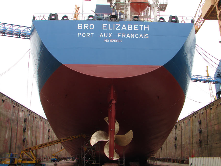
A transom is the aft transverse surface of the hull of some boats and ships forming its stern. Adding both strength and width to the stern, a transom may be flat or curved, and vertical, raked aft (known as an overhung or "counter" stern), or raked forward (and "reversed",[1] also known as retroussé).[2] In small boats and yachts, a flat termination of the stern is typically above the waterline, but large commercial vessels often exhibit vertical transoms that dip slightly beneath the water.[3]
On smaller boats such as dinghies, transoms may be used to support a rudder, outboard motor, or other accessory. On some yachts the transom may include a hinged swim platform, and a lazarette for deck items and leisure toys.[4]
Etymology
[edit]The term was used as far back as Middle English in the 1300s, having come from Latin transversus (transverse) via Old French traversain (set crosswise).[2][5]
History
[edit]This section needs expansion with: content on the evolution of the transom over time. You can help by adding to it. (August 2025) |
Design
[edit]
This section needs expansion with: the advantages and disadvantages of transoms, and the pros and cons of each design. You can help by adding to it. (August 2025) |
Gallery
[edit]-
-
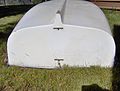
 The transom of the Spirit of Bermuda, made of Bermuda cedar
 -
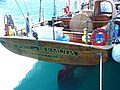
 Raked transom with rudder mounting points
 -
 Reverse transom with rudder mounted under the hull
 -
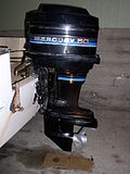 Transom-mounted outboard motor
 -
 An Irwin 44 sloop with a fold-down reverse transom
 -
 Reverse transom with integral access platform

_transom_of_Spirit_of_Bermuda,_2016.jpg)
_-_geograph.org.uk_-_1381157.jpg)


References
[edit]- ^ Jordan, Richard (19 September 2009). "Stern Styles and Transom Types – Sugar Scoop, Reverse, Wineglass, Heartshaped, Canoe, Double Ended, Ducktail". Jordan Yacht Brokerage. Retrieved 2 November 2019.
- ^ a b "transom". Merriam-Webster. Retrieved 2 November 2019.
- ^ "transom". Dictionary.com. Retrieved 2 November 2019.
- ^ "Transom Saver, Outboard Motor Support – Are They Needed?". PartsVu Xchange. 2020-04-30. Retrieved 2022-01-20.
- ^ 2007 Collins dictionary