Hubbry Logo
Vortex engineVortex engineMain
Open search
Vortex engine
Community hub
Vortex engine
logo
8 pages, 0 posts
0 subscribers
Be the first to start a discussion here.
Contribute something
Vortex engine
Vortex engine
from Wikipedia
The solar vortex engine prototype at Universiti Teknologi PETRONAS

The concept of a vortex engine or atmospheric vortex engine (AVE), independently proposed by Norman Louat [1] and Louis M. Michaud,[2] aims to replace large physical chimneys with a vortex of air created by a shorter, less-expensive structure. The AVE induces ground-level vorticity, resulting in a vortex similar to a naturally occurring landspout or waterspout.

An Australian experimental atmospheric vortex using smoke as the tracer. Geoffrey Wickham.

Michaud's patent claims that the main application is that the air flow through the louvers at the base will drive low-speed air turbines, generating twenty percent additional electric power from the heat normally wasted by conventional power plants. That is, the vortex engine's proposed main application is as a "bottoming cycle" for large power plants that need cooling towers.

The application proposed by Louat in his patent claims is to provide a less-expensive alternative to a physical solar updraft tower. In this application, the heat is provided by a large area of ground heated by the sun and covered by a transparent surface that traps hot air, in the manner of a greenhouse. A vortex is created by deflecting vanes set at an angle relative to the tangent of the outer radius of the solar collector. Louat estimated that the minimum diameter of the solar collector would need to be 44 metres (144 ft) or more in order to collect "useful energy". A similar proposal is to eliminate the transparent cover.[3] This scheme would drive the chimney-vortex with warm seawater or warm air from the ambient surface layer of the earth. In this application, the application strongly resembles a dust devil with an air-turbine in the center.

Since 2000, Croatian researchers Ninic and Nizetic (from the Faculty of Electrical Engineering, Mechanical Engineering and Naval Architecture University of Split) have also developed this technology[4] and patents.[5][6]

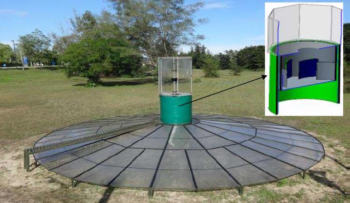
The solar research team at Universiti Teknologi PETRONAS (UTP), Malaysia, headed by Prof. Hussain H. Al-Kayiem, developed the first experimental prototype of a solar vortex power generation (SVPG) technology that uses solar energy as a heat source.[7] The basic prototype was then subjected to a series of developments and performance enhancements by integration with sensible thermal energy storage (TES) and modification in the design of the vortex generator. The team carried out and published an experimental evaluation, theoretical analysis, and computational simulations of the SVPG and compiled the findings in a book which summarizes the fundamentals of this technology.[8]

Theory of operation

[edit]
Conceptual illustration of a vortex engine by Louis Michaud. Diameter 200 m (660 ft.) or greater

(applicable primarily to the Michaud patent)

Elevation (side) view of an 80 m-wide (260 ft) vortex engine. It's constructed mostly of reinforced concrete. (48) is grade level (the surface of the ground).

In operation, the vortex centripetally expels heavier, colder external air (37), and therefore forms a large, low-pressure chimney of hot air (35). It uses about twenty percent of a power-plant's waste heat to drive its air motion. Depending on weather, a large station may create a virtual chimney from 0.2 to 15 kilometres (0.12 to 9.32 mi) high, efficiently venting waste power plant heat into colder upper atmosphere with minimal structure.

The vortex is begun by briefly turning on a diffuse heater (83) and electrically driving the turbines (21) as fans. This moves mildly heated air into the vortex arena (2). The air must have only a mild temperature difference because large temperature differences increase mixing with cold ambient air and reduce efficiency. The heat might be from flue gases, turbine exhaust or small natural gas heaters.

The air in the arena rises (35). This draws more air (33, 34) through directing louvers (3, 5), which cause a vortex to form (35). In the early stages, external airflow (31) is restricted as little as possible by opening external louvers (25). Most of the heat energy is at first used to start the vortex.

In the next stage of start-up, the heater (83) may be turned off and the turbines (21) by-passed by louvers (25). At this time, low-temperature heat from an external powerplant drives the updraft and vortex via a conventional crossway cooling tower (61).

As the air leaves the louvers (3, 5) more rapidly, the vortex increases in speed. The air's momentum causes centrifugal forces on the air in the vortex, which reduce pressure in the vortex, narrowing it further. Narrowing further increases the vortex speed as conservation of momentum causes it to spin faster. The speed of spin is set by the speed of the air leaving louvers (33, 34) and the width of the arena (2). A wider arena and faster louver speed cause a faster, tighter vortex.

Heated air (33, 34) from the crossway cooling tower (61) enters the concrete vortex arena (2) via two rings of directing louvers (3, 5, height exaggerated for clarity) and rises (35). The upper ring of louvers (5) seals the low-pressure end of the vortex with a thick, relatively high-speed air-curtain (34). This substantially increases the pressure difference between the base of the vortex (33) and the outside air (31). In turn, this increases the efficiency of the power turbines (21).

The lower ring of louvers (3) convey large masses of air (33) almost directly into the low-pressure end of the vortex. The lower ring of louvers (3) are crucial to get high mass flows, because air from them (33) spins more slowly, and thus has lower centripetal forces and a higher pressure at the vortex.

Air-driven turbines (21) in constrictions at the inlet of the cooling tower (61) drive electric motor-generators. The generators begin to function only in the last stages of start-up, as a strong pressure differential forms between the base of the vortex arena (33) and the outside air (31) At this time, the bypass louvers (25) are closed.

The wall (1) and bump (85) retain the base of the vortex (35) in ambient winds by shielding the low-velocity air-motion (33) in the base of the arena, and smoothing turbulent airflow. The height of the wall (1) must be five to thirty times the height of the louvers (3, 5) to retain the vortex in normal wind conditions.

To manage safety and wear of the arena (2), the planned maximum speed of the vortex base (33) is near 3 metres per second (9.8 ft/s). The resulting vortex should resemble a large, slow dust-devil of water-mist more than a violent tornado. In uninhabited areas, faster speeds might be permitted so the vortex can survive in faster ambient winds.

Most of the unnamed numbered items are a system of internal louvers and water pumps to manage air velocities and heating as the engine starts.

Criticism and history

[edit]

In early studies it was not absolutely clear that this could be made workable due to cross-wind disruption of the vortex.[9][10] This motivated later studies with wind tunnel empirical validation of the CFD model, which conclude, "The full scale simulations subjected to cross wind show that the power generation capacity is not affected by the cross winds."[11]

Michaud has built a prototype in Utah with colleague Tom Fletcher.[12]

Also, according to Michaud's patent application, the design was initially prototyped with a gasoline-powered 50 cm "fire-swirl".

The University of Western Ontario's wind-tunnel laboratory, through a seed investment from OCE's Centre for Energy, is studying the dynamics of a one-metre version of Michaud's vortex engine.[13]

PayPal founder Peter Thiel's Breakout Labs sponsored an AVE test with a (2012) $300,000 grant.[14] The preliminary results (2015) for which were reported in The Atlantic.[15]

Disambiguation

[edit]

The term "Vortex Engine" also refers to a new kind of internal combustion engine.[16]

See also

[edit]

References

[edit]
[edit]
Revisions and contributorsEdit on WikipediaRead on Wikipedia
from Grokipedia
The atmospheric vortex engine (AVE) is a proposed renewable energy technology that generates electricity by artificially inducing a stable, tornado-like convective vortex within a large cylindrical enclosure, harnessing the kinetic energy of buoyancy-driven upward airflow through peripheral turbines. Developed to capture low-grade thermal energy from sources such as ambient air, solar heating, or industrial waste heat, the device operates by injecting heated air tangentially at the base of the structure to create rotational motion, forming a vortex that extends upward for kilometers without requiring a physical chimney. Unlike conventional heat engines, the AVE minimizes material use and maintenance by relying on natural atmospheric convection, potentially achieving high efficiency in converting diffuse heat into mechanical power. The concept traces its origins to the 1960s and 1970s, when Norman Louat and Louis M. Michaud independently explored harnessing natural vortices like dust devils for energy production, building on early studies of buoyancy-induced swirl flows. Michaud, a Canadian , advanced the idea through detailed thermodynamic analysis and secured a key in 2006, describing a system with a circular wall 50 to 500 meters in diameter and 50 to 150 meters high, where the vortex is ignited via temporary fuel combustion and sustained by peripheral heat exchangers. Small-scale prototypes, including a 4-meter-diameter outdoor model tested in , in 2009, demonstrated successful vortex formation and containment. Further collaborations, such as with Lambton College in 2016, have focused on integrating the technology with recovery from power plants. In theory, a full-scale could output 100 to 500 megawatts from a 400-meter-diameter installation, with vortex heights reaching 1 to 15 kilometers, offering applications beyond power generation such as enhanced regional through entrainment and improved dispersion of pollutants in urban or industrial areas. and field tests of scaled models have validated key parameters like swirl ratio and for stability, though challenges including vortex breakdown from ambient winds and scaling to commercial sizes remain. As an open-ended system, the promises carbon-free operation when paired with renewable heat sources, positioning it as a potential complement to solar and geothermal technologies in portfolios.

Fundamentals

Definition and Concept

The Atmospheric Vortex Engine (AVE) is an atmospheric power generation device that creates an artificial, anchored tornado-like vortex to capture and convert the mechanical energy produced by upward heat convection into usable power. This vortex acts as a dynamic chimney, drawing in warm or humid air tangentially at the base of a cylindrical enclosure and channeling it upward to drive turbines for electricity generation. At its core, the AVE concept employs a relatively short, cost-effective cylindrical wall—50 to 150 meters high—to induce and stabilize the vortex, thereby eliminating the need for the tall, expensive physical chimneys required in conventional systems like solar updraft towers. Heat sources such as , waste industrial heat, or warm provide the thermal differential to initiate , making the device adaptable for renewable or recovery applications. For solar implementations, a vortex requires a minimum base of more than 44 meters to generate useful .

Basic Principles

The vortex engine relies on the fundamental principle of , where heated air rises due to differences in between warmer, less dense air and surrounding cooler, denser air. This creates upward currents, as the density difference Δρ = ρ_cold - ρ_hot drives the buoyant force, with ρ representing air . Angular momentum plays a crucial role in stabilizing the system, achieved by introducing tangential velocity to the air flow through guide vanes at the base, which imparts rotational motion. The resulting rotational motion, combined with the , provides the directing the air inward and maintaining the structural integrity of the against dispersion. In terms of atmospheric , heat input—such as from or solar sources—elevates the air , further reducing its and enhancing to sustain the upward flow. This process creates a low-pressure core within the vortex, governed by , where the total energy remains constant along a streamline:
P+12ρv2+ρgh=constant,P + \frac{1}{2} \rho v^2 + \rho g h = \text{constant},
with increased vv leading to decreased pressure PP.
The vortex engine's operation is analogous to natural atmospheric phenomena like dust devils and tornadoes, which also form through buoyancy-driven and , but the engine provides a controlled and anchored environment to harness these dynamics.

Theory of Operation

Vortex Formation

The formation of the vortex in an atmospheric vortex engine begins with the initiation phase, where heat is applied at the base of a cylindrical to warm the air, inducing buoyant upward . This heat input, typically provided initially by burning fuel such as or using injection, raises the air and creates a density gradient that drives vertical flow. Simultaneously, ambient air is drawn into the through tangential entry slots or ducts positioned around the base, imparting rotational motion or swirl to the rising air column and establishing the initial necessary for vortex development. As the warmed air ascends, it interacts with the enclosure's geometry to form a coherent vortex structure characterized by a central low-pressure eye. The tangential inlets force the air to spiral inward and upward, expelling cooler ambient air radially outward through friction at the boundary layer, which concentrates the flow into a tight core. This radial expulsion and the resulting convergence create a pressure deficit in the eye, often dropping 5-15 kPa below ambient at the base, enhancing inflow. Within the core, the rising air undergoes adiabatic expansion and cooling due to the pressure drop, lowering temperatures and further promoting buoyancy while maintaining the vortex's integrity up to altitudes of 10-15 km. Sustaining the vortex requires specific stability factors related to the enclosure's dimensions and flow control elements. The cylindrical wall must have a minimum height of 50-150 m and diameter of 100-200 m for prototype-scale systems to allow sufficient development of centripetal forces that prevent vortex breakdown and radial . Guide vanes or adjustable deflectors at the tangential inlets enforce consistent , distributed as vθ=Γ2πrv_\theta = \frac{\Gamma}{2\pi r}, where vθv_\theta is the tangential speed, Γ\Gamma is the circulation strength, and rr is the radial distance from ; this potential vortex profile ensures rotational stability without excessive shear. The vortex self-regulates its diameter by balancing centrifugal forces against radial pressure gradients, with convergence confined to a thin to minimize energy loss from . Cross-wind effects were initially a concern for disrupting the nascent vortex, but simulations demonstrate that once established, the vortex self-stabilizes against ambient winds up to certain speeds, aided by the protective cylindrical wall that shields the base during formation. In model tests, such as a 4 m , stable vortices formed and persisted despite external flows, confirming robustness for operational scales.

Energy Extraction Mechanisms

The energy extraction in a vortex engine primarily involves harnessing the from the high-velocity tangential inflows and the vertical within the controlled vortex structure. Turbines are strategically placed to convert these and differentials into mechanical work, which is then transformed into electrical power via generators. This process exploits the vortex's ability to maintain a low-pressure core, driving continuous without the need for extensive structural height typical of traditional chimneys. Turbine placement typically includes multiple peripheral turbines located at the tangential inlets around the base of the cylindrical enclosure, positioned upstream of deflectors to capture the incoming air's before it contributes to vortex rotation. These turbines, often horizontal-axis types, extract power from the high-speed inflows induced by the . The peripheral turbines capture the energy from the inflows, which include both rotational and vertical components driven by the low-pressure core. Power output is estimated using the standard wind power equation adapted to the vortex flows: P=12ρAv3ηP = \frac{1}{2} \rho A v^3 \eta, where PP is the extractable power, ρ\rho is air (typically 1.2 kg/m³ at ), AA is the effective swept area of the s, vv is the through the s, and η\eta is the overall system accounting for , generator, and aerodynamic losses (often 30-50% for modern designs). To derive this, start with the kinetic energy flux in the airflow: the is m˙=ρAv\dot{m} = \rho A v, and the kinetic energy per unit mass is 12v2\frac{1}{2} v^2. Thus, the total available kinetic power is m˙×12v2=ρAv×12v2=12ρAv3\dot{m} \times \frac{1}{2} v^2 = \rho A v \times \frac{1}{2} v^2 = \frac{1}{2} \rho A v^3. Multiplying by η\eta yields the usable power, reflecting Betz's limit (maximum η0.593\eta \approx 0.593 for ideal extraction) adjusted for practical factors. In vortex engines, velocities vv can reach 20-50 m/s at locations, enabling outputs with efficiencies up to 20% higher than conventional convective systems due to the vortex's amplification of draft. The vortex engine facilitates heat-to-power conversion by functioning as an enhanced "chimney" that amplifies natural or artificial updraft through rotational dynamics, drawing in heated air at the base and expelling it at altitude. In waste heat applications, low-grade thermal energy (e.g., from industrial processes at 50-100°C) is supplied via perimeter heaters, creating buoyancy that sustains the vortex; this integrates as a bottoming cycle for existing power plants, converting otherwise wasted heat into additional mechanical work via the turbines. The process leverages the tropospheric lapse rate for a colder effective sink temperature, potentially achieving Carnot-limited efficiencies of 10-15% for ambient conditions, with the vortex structure boosting practical conversion by maintaining stable high-velocity flows. For scaling, a with 100 m and 200 m —using moderate input of 500-1000 MW —could yield 100-200 MW electrical output, assuming vortex core diameters of 20-50 m and inflow velocities of 30 m/s across arrays totaling 10,000 m² swept area. This scales with heat supply and enclosure size, where larger diameters increase peripheral capacity proportionally to , while enhances updraft strength via greater .

Design and Components

Core Structural Elements

The core structural elements of an atmospheric vortex engine (AVE) form a robust, cylindrical designed to contain and sustain a controlled convective vortex. This typically consists of a vertical, circular or polygonal wall with a ranging from 50 to 500 meters and a of 50 to 150 meters, such as a preferred configuration of 300 meters in and 80 meters high. Constructed from strong, impermeable materials with a smooth inner surface to minimize and , the often features a base and floor for stability, along with an external support structure to withstand wind loads and pressure differentials. The design ensures that air enters solely through designated inlets, preventing unwanted infiltration and maintaining vortex integrity. Inlet systems at the base of the introduce ambient air tangentially to induce rotational flow. These consist of multiple linear slots or ducts, typically 2 to 10 meters high and positioned around the perimeter, equipped with adjustable restrictors to control volume and vertical deflectors or guide vanes—often fixed or adjustable airfoil-shaped elements in one or two levels—to direct air at precise tangential angles for optimal swirl. Integrated heat input mechanisms, such as cross-flow wet cooling towers approximately 30 meters high or optional solar collectors with transparent roofs and open rims, warm the incoming air using sources like industrial exhaust or warm , or direct solar radiation, thereby enhancing and vortex formation. The employs an open-top configuration, allowing to extend naturally into the atmosphere without a physical , potentially reaching heights of 10 to 15 kilometers. An optional diffuser at the base or outlets serves to decelerate post-energy extraction, distributing it evenly to minimize and recover . Auxiliary elements support operation and monitoring, including sensors embedded in the structure to measure key parameters such as , , , , and flow direction, enabling real-time adjustments via a . Startup mechanisms, such as peripheral forced-draft fans, jets, or temporary burners (e.g., a ring), initiate the initial rotational flow and heating for 10 to 30 minutes until the self-sustaining vortex forms.

Variations and Adaptations

The solar variant of the atmospheric vortex engine, known as the solar vortex engine (SVE), integrates ground-level solar air collectors to heat incoming air, replacing the tall chimney structures of traditional solar updraft towers with a shorter vortex generation system for enhanced scalability and cost-effectiveness. This design leverages solar radiation to drive convective updraft within the vortex, with experimental models demonstrating stable operation through tangential air admission at the base. A minimum diameter of approximately 50 meters is required to achieve sufficient buoyancy and vortex stability, ensuring the anchored tornado-like flow extends adequately for energy extraction. Recent 2025 experimental studies have enhanced the SVE by incorporating a black-coated glass porous medium in the collector base for improved thermal storage, allowing sustained operation during low-insolation periods and increasing overall system efficiency by 20% through better heat retention and transfer, particularly improving late-day performance. The variant adapts the as a bottoming cycle for industrial plants, utilizing low-grade exhaust sources like gases or to preheat the air and sustain the vortex without additional fuel input. This configuration couples directly to power facilities, such as or nuclear plants, where the vortex acts as an enhanced while generating supplementary power. By converting approximately 20% of a plant's —typically 1000 MW from a 500 MW electrical output—into mechanical work, this adaptation yields an overall gain of 20%, increasing net power production from 500 MW to 700 MW in modeled scenarios. Hybrid models extend the vortex engine's versatility by combining it with other renewables, such as integrating photovoltaic panels along the collector periphery or positioning wind turbines in the base airflow to capture tangential kinetic energy. These hybrids achieve combined electrical efficiencies of up to 14%, with the vortex enhancing airflow for the auxiliary components during variable conditions. Geothermal integration is possible through subsurface heat exchangers feeding warm fluids to the base, while scaled-down versions with 10-50 meter diameters enable micro-generation for remote or distributed applications, producing 50-200 kW suitable for off-grid communities. Material adaptations focus on cost reduction by employing tensioned membranes, such as fabric or sheets for the cylindrical enclosure and annular roof, instead of rigid or steel towers, which lowers construction expenses by 30-50% while maintaining structural integrity under vortex loads. These lightweight membranes, often coated for durability (e.g., with aluminum ), allow flexible deployment in diverse terrains and facilitate easier scaling for both large-scale and installations.

History and Development

Origins and Early Proposals

Early concepts for harnessing rotational atmospheric for energy production date back to the . In 1964, French engineer Edgard Nazare patented an artificial cyclone generator (FR1439849A), which used solar-heated updrafts to drive turbines for mechanical power, serving as a precursor to later vortex-based systems. Building on studies of natural vortices, Canadian engineer Louis M. Michaud proposed in 1975 the use of anchored vortices to replace physical chimneys in convective power systems, as outlined in the Bulletin of the . The modern vortex engine concept advanced in the late 1990s and early 2000s, drawing inspiration from natural phenomena such as tornadoes and dust devils. Australian physicist Norman Louat proposed an "unbounded vortical chimney" in 1999, envisioning tangential air injection to induce a self-sustaining vortex as a cost-effective alternative to traditional solar towers. In Louat's design, detailed in his Australian (AU2503399A), atmospheric maintains the updraft without a massive physical structure, aiming to reduce costs for solar-heated air power generation. Independently, Michaud refined his ideas in the early , founding AVEtec Energy Corporation around to develop the atmospheric vortex engine () for recovery from industrial sources. Michaud's creates an "anchored tornado"—a stable, controlled vortex within a circular —to extract from upward convective flow via base turbines, enabling baseload without solar intermittency. His Patent 7,086,823 B2, granted in , describes tangential introduction of preheated air into a cylindrical base to initiate and sustain the vortex, deriving energy from airflow . These proposals were influenced by prior solar chimney research, including the 1982 Manzanares prototype in , which generated 50 kW using a 195-meter and expansive collector to validate buoyancy-driven . However, its high structural costs and limitations spurred innovations like Louat's and Michaud's vortex enhancements for more compact designs. This work provided the theoretical foundation, evolving from patents to experimentation.

Prototypes and Experimental Research

In 2005, Michaud collaborated with on a small-scale demonstration in , using a 15 m tall, 30 m tower fueled by circular combustion to simulate and create artificial vortices. The setup confirmed low-pressure core formation and sustained rotational flow without turbines. In 2009, Michaud constructed an outdoor prototype of the AVE in Petrolia, Ontario, with a 4 m cylindrical that successfully generated a stable vortex. This test validated tangential air inlets and heat input for anchored . In 2012, Breakout Labs awarded $300,000 to AVEtec to support prototype development and modeling of vortex dynamics and scalability, in partnership with Lambton College. This led to an 8 m diameter outdoor prototype at the college, tested around 2015, which produced a 40 m tall vortex with a 30 cm diameter core and powered a 1 m diameter , demonstrating feasibility for recovery. During the 2010s, researchers at in developed a solar-integrated with an 8.8 m collector and 1 m high . The system achieved stable vortex operation, with mean air temperatures of 321 and heat fluxes up to 3700 W/m² under Perspex covering, validating solar-driven . At Western University (formerly ), wind-tunnel experiments in the early on a 1 m confirmed the vortex engine's resilience to cross-winds via controlled airflow simulations, informing anchoring designs. Croatian research from 2007 to 2015, led by Sandro Nižetić at the , focused on numerical simulations of gravitational vortex columns as alternatives. Models with three-layer flow structures, incorporating 35 m/s and 45°C air , predicted efficiencies of about 12.3%—higher than the 1-2% of conventional chimneys—suggesting 30-50% relative gains from reduced height and enhanced .

Applications and Potential

Power Generation Uses

The atmospheric vortex engine (AVE) can be integrated as a bottoming cycle in fossil fuel or nuclear power plants to utilize waste heat, converting thermal exhaust into additional mechanical energy without requiring extra fuel input. By anchoring a controlled vortex within a circular enclosure, the system lowers the cold sink temperature, potentially increasing overall plant output by up to 20%—for example, boosting a 500 MW facility to 700 MW using 1000 MW of waste heat. This integration replaces traditional cooling towers, enhancing efficiency by drawing in ambient air tangentially to form the vortex while extracting energy via peripheral turbines. In standalone renewable applications, solar variants of the vortex engine serve as cost-effective alternatives to solar updraft towers, using solar-heated air collectors to drive the vortex without the need for tall . Proposed large-scale designs employ enclosures 50 to 500 meters in diameter instead of a 200-meter , reducing material costs and land footprint while generating velocities for power. Prototypes have demonstrated power outputs of around 63 kW in small-scale tests with tangential velocities of 8 m/s and axial velocities of 11 m/s, achieving thermal efficiencies up to 62% when integrated with . Theoretical overall system efficiencies for solar operations could reach up to 30%. For grid-scale deployment, arrays of vortex engines in hot, arid climates could form gigawatt-level power farms by scaling multiple 200-300 meter units, each capable of 100-500 MW output from ambient or sources. Hybrid configurations combine power generation with , where the vortex updraft facilitates multi-stage flash or humidification-dehumidification processes using warm seawater as the heat input, enabling co-production of and in coastal regions. applications yield higher effective efficiencies—potentially 20% or more—since the input energy is "free," contrasting with solar setups where conversion depends on insolation levels.

Environmental and Efficiency Advantages

The atmospheric vortex engine (AVE) offers significant reductions in construction materials compared to traditional solar chimney systems, as it replaces tall physical chimneys—often exceeding 200 meters in height—with a shorter cylindrical typically 50 to 150 meters tall, thereby minimizing the need for extensive and reinforcements. This design leverages centrifugal forces to maintain the vortex, avoiding the structural demands of a solid stack and potentially lowering embodied carbon emissions from by enabling more compact . By harnessing ambient heat, waste industrial heat, or solar-driven , the displaces fuel-based power generation, directly contributing to carbon through zero-emission production during operation. Integration with thermal power plants allows the engine to convert that would otherwise be lost, reducing overall fuel consumption and associated CO₂ emissions from sources like or gas plants. The AVE requires a minimal land footprint, utilizing the natural ground surface for heat collection without the expansive solar collector fields needed for photovoltaic arrays or solar updraft towers, which can span several square kilometers. It also eliminates water usage for cooling, as the system can employ dry heat exchangers or rely on atmospheric , making it suitable for arid regions where limits other technologies. Efficiency improvements arise from the vortex's ability to amplify upward draft through rotational dynamics, extending the effective stack height to 1–15 kilometers without additional physical construction and achieving thermal-to-electric efficiencies up to 15%, far surpassing the 0.2% of prototype solar chimneys. This amplification enhances air velocity within the core, boosting output by capturing more from buoyancy-driven flow compared to non-rotational natural draft systems.

Challenges and Criticisms

Technical Limitations

One key technical limitation of the atmospheric vortex engine (AVE) is , which can lead to breakdown under high ambient winds or insufficient input. Buoyancy-driven vortices in the AVE are prone to wandering, tilting, and when exposed to crosswinds, potentially disrupting the controlled tornado-like structure essential for energy extraction. Maintaining stability requires a minimum (CAPE) of approximately 1000 J/kg to sustain the upward , corresponding to a modest surface differential of around 5-10°C between the heated inflow and ambient air; larger differentials risk excessive mixing with cooler surroundings, further destabilizing the vortex. Scale-up to commercial sizes introduces challenges related to energy losses, particularly from along the vortex path. While friction losses diminish in very large-diameter conduits due to reduced surface-to-volume ratios, achieving optimal performance demands precise sizing, with (CFD) analyses indicating effective diameters of 100-300 m for balancing drive against dissipative effects. Beyond this range, inefficiencies arise from incomplete conservation in oversized structures, limiting . Material stresses pose another constraint, stemming from the high tangential velocities within the vortex—reaching 40-80 m/s (144-288 km/h) at outlets and 10-30 m/s (36-108 km/h) at entry points—which impose significant centrifugal and shear forces on the enclosing cylindrical . These forces necessitate durable, impervious materials capable of withstanding cyclic loading from vortex fluctuations, with risks heightened in larger installations where speeds amplify structural demands. Startup and control mechanisms add operational hurdles, as initiating the vortex typically requires an auxiliary heat source, such as fuel-fired burners, to generate initial for 10-30 minutes before ambient or can sustain it. Control is further complicated by sensitivity to ambient , which can decrease stability and increase energy requirements for vortex maintenance due to changes in air properties. Historical prototypes have highlighted these sensitivities, while recent designs incorporate deflectors for improved stability.

Economic and Practical Barriers

The development and deployment of the Atmospheric Vortex Engine (AVE) face substantial economic hurdles, primarily stemming from high initial capital expenditures required for custom-engineered components and infrastructure. Estimates for constructing a 200-megawatt-scale facility range around $60 million, reflecting the need for specialized vortex stabilization systems, tangential air inlets, and turbine arrays not readily available from standard suppliers. Smaller prototypes, such as the 1-kilowatt model funded at Lambton College, have been supported by of approximately $300,000, underscoring the reliance on external funding for early-stage validation. However, remains uncertain without government subsidies, as the technology's unproven contrasts with subsidized mature renewables. As of , recent reviews highlight ongoing challenges including high construction costs for tall chimneys and large collector areas, dependency on constant heat sources limiting flexibility, and a lack of optimal porous media for storage and efficiency improvements. Scalability from prototypes to commercial applications remains unachieved, with no full-scale deployments reported. Practical imposes additional logistical barriers, necessitating large, flat expanses of land in regions with high (CAPE ≥ 1,000 J/kg), such as hot and arid deserts where surface heating can sustain the vortex. These locations, often remote, increase transmission costs and limit accessibility. Regulatory challenges further complicate adoption, particularly concerning atmospheric interference; the artificial vortex could generate affecting , requiring compliance with regulations and potential no-fly zones around installations, similar to restrictions for other tall structures. Maintenance demands add to operational costs, as the open-air design exposes components to environmental stressors like and variable , necessitating frequent inspections and repairs to guide vanes and anchoring systems. The AVE struggles against established alternatives in the , where photovoltaic (PV) solar achieves levelized costs of electricity (LCOE) below $0.05/kWh in optimal regions, driven by and declining panel prices. Proponents estimate AVE LCOE at around $0.03/kWh for mature deployments, but practical uncertainties in vortex stability and could push realized costs to $0.10/kWh or higher, diminishing competitiveness without technological breakthroughs.

Current Status and Future Prospects

Recent Advancements

In 2024, (CFD) simulations demonstrated the significant impact of solar radiation on vortex engine performance. A study published in AIP analyzed the effects of varying solar intensities (400 to 1000 W/m²) on updraft in a solar vortex engine (SVE), revealing a 37% increase in vortex updraft with concentrated solar heating, validating the direct between radiation concentration and enhanced dynamics. A 2025 experimental assessment at Hawija Technical Institute in incorporated a —black-coated glass beads over an aluminum absorber plate—into an SVE to enable continuous operation. This setup achieved of 48.7% at 16:00 (compared to 46.4% without the medium) and boosted mechanical power output by approximately 30% (56.7 mW vs. 43.6 mW) during late-afternoon low-radiation periods, though peak efficiency was lower at 46.4% (vs. 54.16% without); air velocity decreased by 15% at peak solar hours but remained stable later due to heat retention. A short review published in September 2025 synthesized recent enhancements to the SVE, highlighting optimizations such as guide blades and adjusted orifice diameters that achieve tangential-to-axial ratios up to 7.5, with tangential velocities up to 2.83 m/s and axial speeds of 1.75 m/s. These modifications, drawn from multiple studies, yielded gains including 17.4% from black coatings and up to 62% with extended thermal storage through improved swirling airflow and structural refinements like conical . As of November 2025, research has focused on small-scale laboratory tests, with no full-scale prototypes constructed; broader efforts emphasize hybrid models, though specific post-2020 university-led grants in Iraq remain unverified in available sources.

Ongoing Research and Commercialization

Researchers at Universiti Teknologi PETRONAS in Malaysia continue to advance the solar vortex engine (SVE) through experimental and numerical studies focused on hybrid configurations that integrate solar thermal collection with vortex-induced airflow for enhanced power generation. Recent work includes thermodynamic modeling of power cycles to optimize energy extraction from heated air vortices, demonstrating potential efficiencies in tropical climates, though overall conversion efficiency remains low, comparable to solar chimney power plants. Complementary research evaluates porous media enhancements for SVE thermal storage, where black-coated glass beads retained heat to sustain vortex operation into late afternoon, achieving 48.7% despite reduced solar input. Analogous efforts in gravitational vortex systems utilize CFD simulations to model vortex stability and integration with power grids for low-head hybrids, offering insights into dynamics in confined vortices applicable to atmospheric systems. Commercialization remains in early stages, with no operational pilot plants as of November 2025, though scaling analyses suggest economic viability for SVE deployments in arid regions like the and . Projections indicate that expanding collector diameters from 5 m to 600 m could yield 5-17 MW per unit at reduced costs, potentially through international collaborations similar to the defunct AVEtec initiative funded in 2012. Successor ventures have not secured recent , but reviews highlight the need for funded prototypes to demonstrate grid-scale integration by the 2030s. Key research gaps include assessments of long-term durability under variable weather and on vortex-induced microclimates, as current prototypes lack multi-year operational . As of November 2025, research remains primarily academic and small-scale, with no major commercialization advancements reported. If scaled successfully, vortex engines could contribute modestly to global low-carbon power, aligning with broader renewable projections for growth in hybrid thermal systems by 2050, though specific impacts depend on overcoming barriers.

References

Add your contribution
Related Hubs
Contribute something
User Avatar
No comments yet.