Hubbry Logo
Instrument landing systemInstrument landing systemMain
Open search
Instrument landing system
Community hub
Instrument landing system
logo
8 pages, 0 posts
0 subscribers
Be the first to start a discussion here.
Instrument landing system
from Wikipedia
Diagram of an instrument landing system (ILS) approach

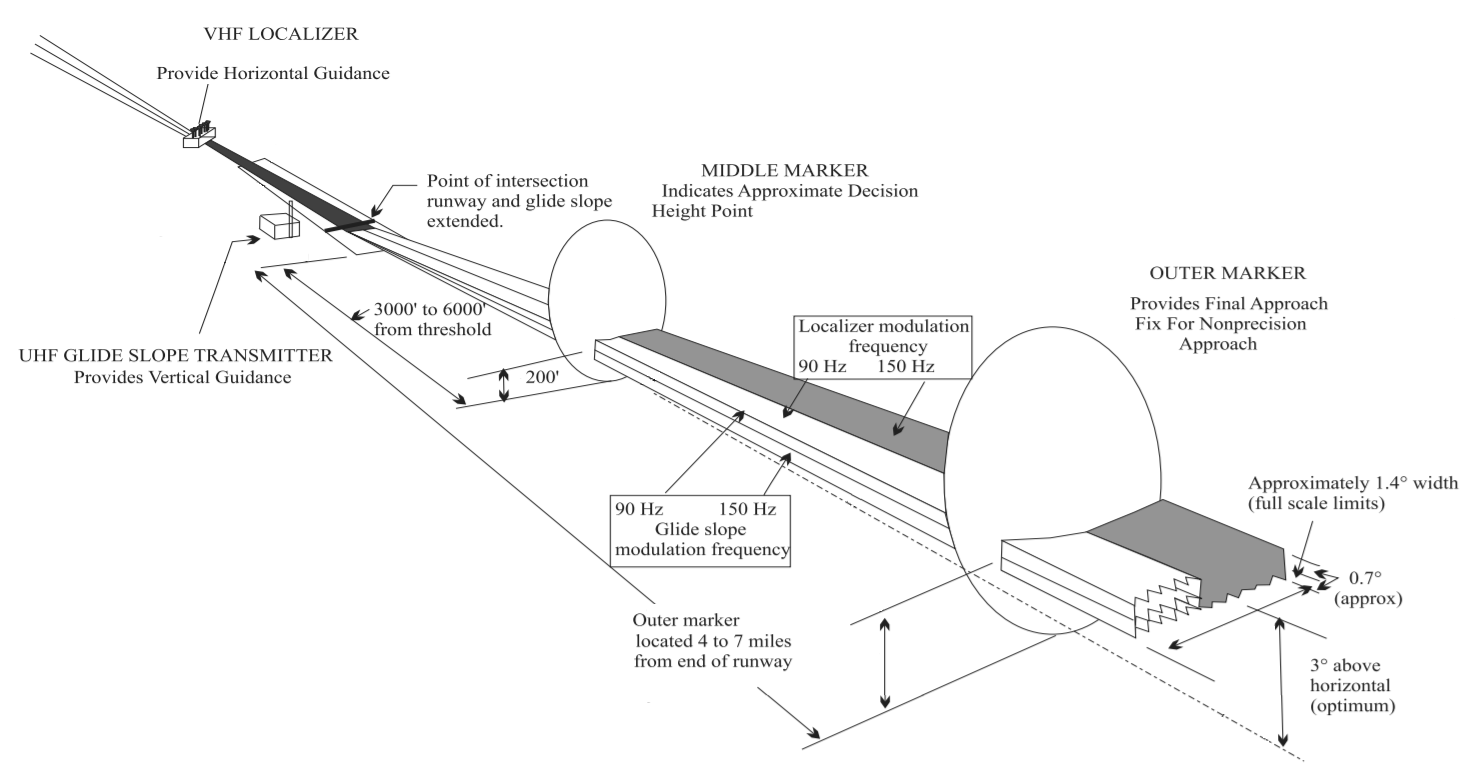
In aviation, the instrument landing system (ILS) is a precision radio navigation system that provides short-range guidance to aircraft to allow them to approach a runway at night or in bad weather. In its original form, it allows an aircraft to approach until it is 200 feet (61 m) over the ground, within a 12 mile (800 m) of the runway. At that point the runway should be visible to the pilot; if it is not, they perform a missed approach. Bringing the aircraft this close to the runway dramatically increases the range of weather conditions in which a safe landing can be made. Other versions of the system, or "categories", have further reduced the minimum altitudes, runway visual ranges (RVRs), and transmitter and monitoring configurations designed depending on the normal expected weather patterns and airport safety requirements.

View of the primary component of the ILS, the localizer, which provides lateral guidance. The transmitter and antenna are on the centerline at the opposite end of the runway from the approach threshold. Photo of Indra's Normarc localizer, taken at the runway 06R of the Montréal–Trudeau International Airport, Canada.

ILS uses two directional radio signals, the localizer (108 to 112 MHz frequency), which provides horizontal guidance, and the glideslope (329.15 to 335 MHz frequency) for vertical guidance. The relationship between the aircraft's position and these signals is displayed on an aircraft instrument, often as additional pointers in the attitude indicator. The pilot attempts to maneuver the aircraft to keep the indicators centered while they approach the runway to the decision height. Optional marker beacon(s) provide distance information as the approach proceeds, including the middle marker (MM), placed close to the position of the (CAT 1) decision height. Markers are largely being phased out and replaced by distance measuring equipment (DME).

To aid the transition from instrument landing to visual, lighting on the runway is often extended towards the decision point using a series of high-intensity lights known as the approach lighting system.[1]

History of precision approach landing systems

[edit]

A number of radio-based landing systems were developed between the 1920s and 1940s, notably the Lorenz beam, which was a blind-landing radio navigation system developed by C. Lorenz AG for bad weather landing, which saw relatively wide use in Europe and was also installed on a number of airports on other continents worldwide prior to World War II.[2] Later also the patent for adding vertical guidance like in today's ILS was awarded.[3][4]

The US-developed SCS-51 system provided a better accuracy for vertical and horizontal guidance. Many sets were installed at airbases in the United Kingdom during World War II. After the formation of the International Civil Aviation Organization (ICAO) in 1947, ILS was selected as the first international standard precision approach system[5] and was published in ICAO Annex 10 in 1950.[6] Further development enabled ILS systems to provide up to CAT-III approaches.[5]

The Precision approach radar (PAR) radar-based ground-controlled approach (GCA), provides the pilot with the necessary horizontal and vertical guidance via VHF- or UHF-voice-communication link. The ATC-controller “talks the pilot down” with the PAR derived guidance information displayed on a special Plan position indicator (PPI) via VHF- or UHF-voice-communication. PAR GCA requires no equipment in the aircraft other than the VHF- or UHF-communication equipment, but requires the pilot and controller to be certified for this use.

The second ICAO standard system for precision approach up to CAT-III is the microwave landing system (MLS) which was also planned for implementation by NATO to replace PAR. Due to the foreseen availability of cost-free GPS service for civil use and later the promise of DGPS, to provide additional correctional data via a VHF-Data-Link to improve reliability up to CAT-I level, most states opted to delay, until today, the implementation of MLS. In addition to the cost for the ground-based MLS system, aircraft operators were forced to equip aircraft, in addition to the MLS-receiver, with a C-Band antenna. The retrofit of a C-Band antenna in the aircraft's fuselage is more time consuming and costly than just retrofitting an MLS-receiver. However more than thousand fixed and transportable MLS systems have been deployed, e.g. in Europe, and more than thousand civil and military aircraft were equipped with MLS equipment and antenna and in use for about a decade.

While the promised availability of free access to GPS signals and later additional global navigation satellite systems (GNSSs) for precision approaches reducing the need for the airport infrastructure compared to a single ILS-system (ILS-LLZ, GP and associated Monitors) looked promising. Ensuring safe 24/7 operation identical to ILS with the same continuity of service, under all operational weather conditions, aircraft orientation during all phases of a flight proved to be impossible without an additional augmentation VHF-Data-Link. One reason is the weak satellite based signals, which unlike much stronger ILS- or MLS- signals, very sensitive even to very weak RFI-, intentional Jamming- or Spoofing signals.

The DGPS system was, after further development and modifications, standardized by ICAO as GBAS ground-based augmentation system, in the US known as Local-Area Augmentation System (LAAS). Today GBAS is the third ICAO standard system for precision landing capable of up to CAT-III. Work on standards to support multi-constellation, which means adding support for the now available Galileo, GLONASS and BeiDou GNSS system is ongoing. Like for MLS aircraft require for GBAS a receiver for the GBAS datalink and a horizontally polarized VHF-antenna. While IFR certified civil aircraft are already all equipped with horizontally polarized VHF antennas for ILS- and VOR-reception, some military aircraft only have vertically polarized VHF antennas for VHF voice communication (e.g. USNY). While ICAO also standardized the use of the additional vertical polarization, so far no vertically polarized GBAS installation have been published to be available.

Similar to the MLS until today compared to ILS-installations that are in use worldwide, only a limited number of GBAS systems have been deployed and are still in use currently. While in principle a single omnidirectional augmentation signal was initially thought to suffice to provide service to one or even other airports within radio Line-of-sight propagation (RLOS), providing sufficient coverage within all approach paths provided to be difficult for complex airport layouts with large buildings and Hangars and varying aircraft antenna pattern. Today in Europe mostly serve only a single or parallel runways, e.g. Frankfurt am Main, but not all runways. By 2015, the number of US airports supporting ILS-like LPV approaches exceeded the number of ILS installations,[7] and this may lead to the eventual removal of ILS at most airports.

ILS therefore remains the only available precision approach systems supported by all IFR equipped civil aircraft.

Principle of operation

[edit]
ILS planes

An instrument landing system operates as a ground-based instrument approach system that provides precision lateral and vertical guidance to an aircraft approaching and landing on a runway, using a combination of radio signals and, in many cases, high-intensity lighting arrays to enable a safe landing during instrument meteorological conditions (IMC), such as low ceilings or reduced visibility due to fog, rain, or blowing snow.

Beam systems

[edit]

Previous blind landing radio aids typically took the form of beam systems of various types. These normally consisted of a radio transmitter that was connected to a motorized switch to produce a pattern of Morse code dots and dashes. The switch also controlled which of two directional antennae the signal was sent to. The resulting signal sent into the air consists of dots sent to one side of the runway and dashes to the other. The beams were wide enough so they overlapped in the center.[8]

To use the system an aircraft only needed a conventional radio receiver. As they approached the airport they would tune in the signal and listen to it in their headphones. They would hear dots and dashes (Morse code "A" or "N"), if they were to the side of the runway, or if they were properly aligned, the two mixed together to produce a steady tone, the equisignal. The accuracy of this measurement was highly dependent on the skill of the operator, who listened to the signal on earphones in a noisy aircraft, often while communicating with the tower.[8]

Accuracy of the system was normally on the order of 3 degrees in azimuth. While this was useful for bringing the aircraft onto the direction of the runway, it was not accurate enough to safely bring the aircraft to visual range in bad weather; the radio course beams were used only for lateral guidance, and the system was not enough on its own to perform landings in heavy rain or fog. Nevertheless, the final decision to land was made at only 300 metres (980 ft) from the airport.[8]

ILS concept

[edit]

The ILS, developed just prior to the start of World War II, used a more complex system of signals and an antenna array to achieve higher accuracy. This requires significantly more complexity in the ground station and transmitters, with the advantage that the signals can be accurately decoded in the aircraft using simple electronics and displayed directly on analog instruments.[8] The instruments can be placed in front of the pilot, eliminating the need for a radio operator to continually monitor the signals and relay the results to the pilot over the intercom.

Key to its operation is a concept known as the amplitude modulation index, a measure of how strongly the amplitude modulation is applied to the carrier frequency. In the earlier beam systems, the signal was turned on and off entirely, corresponding to a modulation index of 100%. The determination of angle within the beam is based on the comparison of the audible strength of the two signals.

In ILS, a more complex system of signals and antennas varies the modulation of two signals across the entire width of the beam pattern. The system relies on the use of sidebands, secondary frequencies that are created when two different signals are mixed. For instance, if one takes a radio frequency signal at 10 MHz and mixes that with an audible tone at 2500 Hz, four signals will be produced, at the original signals' frequencies of 2500 and 10000000 Hz, and sidebands 9997500 and 10002500 Hz. The original 2500 Hz signal's frequency is too low to travel far from an antenna, but the other three signals are all radio frequency and can be effectively transmitted.[9]

ILS starts by mixing two modulating signals to the carrier, one at 90 Hz and another at 150. This creates a signal with five radio frequencies in total, the carrier and four sidebands. This combined signal, known as the CSB for "carrier and sidebands", is sent out evenly from an antenna array. The CSB is also sent into a circuit that suppresses the original carrier, leaving only the four sideband signals. This signal, known as SBO for "sidebands only", is also sent to the antenna array.[9]

For lateral guidance, known as the localizer, the antenna is normally placed centrally at the far end of the runway and consists of multiple antennas in an array normally about the width of the runway. Each individual antenna has a particular phase shift and power level applied only to the SBO signal such that the resulting signal is retarded 90 degrees on the left side of the runway and advanced 90 degrees on the right. Additionally, the 150 Hz signal is inverted on one side of the pattern, another 180 degree shift. Due to the way the signals mix in space the SBO signals destructively interfere with and almost eliminate each other along the centerline, leaving the CSB signal predominating. At any other location, on either side of the centerline, the SBO and CSB signals combine in different ways so that one modulating signal predominates.[9]

A receiver in front of the array will receive both of these signals mixed together. Using simple electronic filters, the original carrier and two sidebands can be separated and demodulated to extract the original amplitude-modulated 90 and 150 Hz signals. These are then averaged to produce two direct current (DC) signals. Each of these signals represents not the strength of the original signal, but the strength of the modulation relative to the carrier, which varies across the beam pattern. This has the great advantage that the measurement of angle is independent of range.[9]

The two DC signals are then sent to a conventional voltmeter, with the 90 Hz output pulling the needle right and the other left. Along the centreline the two modulating tones of the sidebands will be cancelled out and both voltages will be zero, leaving the needle centered in the display. If the aircraft is far to the left, the 90 Hz signal will produce a strong DC voltage (predominates), and the 150 Hz signal is minimised, pulling the needle all the way to the right. This means the voltmeter directly displays both the direction and magnitude of the turn needed to bring the aircraft back to the runway centreline.[9] As the measurement compares different parts of a single signal entirely in electronics, it provides angular resolution of less than a degree, and allows the construction of a precision approach.[9]

Although the encoding scheme is complex, and requires a considerable amount of ground equipment, the resulting signal is both far more accurate than the older beam-based systems and is far more resistant to common forms of interference. For instance, static in the signal will affect both sub-signals equally, so it will have no effect on the result. Similarly, changes in overall signal strength as the aircraft approaches the runway, or changes due to fading, will have little effect on the resulting measurement because they would normally affect both channels equally. The system is subject to multipath distortion effects due to the use of multiple frequencies, but because those effects are dependent on the terrain, they are generally fixed in location and can be accounted for through adjustments in the antenna or phase shifters.[9]

Normal limits of localizer coverage.

Additionally, because it is the encoding of the signal within the beam that contains the angle information, not the strength of the beam, the signal does not have to be tightly focussed in space. In the older beam systems, the accuracy of the equisignal area was a function of the pattern of the two directional signals, which demanded that they be relatively narrow. The ILS pattern can be much wider. ILS installations are normally required to be usable within 10 degrees on either side of the runway centerline at 25 nautical miles (46 km; 29 mi), and 35 degrees on either side at 17 nautical miles (31 km; 20 mi). This allows for a wide variety of approach paths.[10]

The glideslope works in the same general fashion as the localizer and uses the same encoding, but is normally transmitted to produce a centerline at an angle of 3 degrees above horizontal[a] from an antenna beside the runway instead of the end. The only difference between the signals is that the localizer is transmitted using lower carrier frequencies, using 40 selected channels between 108.10 MHz and 111.95 MHz, whereas the glideslope has a corresponding set of 40 channels between 328.6 and 335.4 MHz. The higher frequencies generally result in the glideslope radiating antennas being smaller. The channel pairs are not linear; localizer channel 1 is at 108.10 and paired with glideslope at 334.70, whereas channel two is 108.15 and 334.55. There are gaps and jumps through both bands.[10][11]

Common type of illustration showing misleading examples of ILS localizer and glideslope emissions

Many illustrations of the ILS concept show the system operating more similarly to beam systems with the 90 Hz signal on one side and the 150 on the other. These illustrations are inaccurate; both signals are radiated across the entire beam pattern, it is their relative difference in the depth of modulation (DDM) that changes dependent upon the position of the approaching aircraft.

Using ILS

[edit]

An instrument approach procedure chart (or 'approach plate') is published for each ILS approach to provide the information needed to fly an ILS approach during instrument flight rules (IFR) operations. A chart includes the radio frequencies used by the ILS components or navaids and the prescribed minimum visibility requirements.

An aircraft approaching a runway is guided by the ILS receivers in the aircraft by performing modulation depth comparisons. Many aircraft can route signals into the autopilot to fly the approach automatically. An ILS consists of two independent sub-systems. The localizer provides lateral guidance; the glide slope provides vertical guidance.

Localizer

[edit]
The localizer station for runway 27R at Hannover Airport in Germany

A localizer (LOC, or LLZ until ICAO standardisation[12]) is an antenna array normally located beyond the departure end of the runway and generally consists of several pairs of directional antennas.

The localizer will allow the aircraft to turn and match the aircraft with the runway. After that, the pilots will activate approach phase (APP).

Glide slope (G/S)

[edit]
Glide slope station for runway 09R at Hannover Airport in Germany
Given this display, the pilot must correct to the left and a little upwards.

The pilot controls the aircraft so that the glide slope indicator remains centered on the display to ensure the aircraft is following the glide path of approximately 3° above horizontal (ground level) to remain above obstructions and reach the runway at the proper touchdown point (i.e. it provides vertical guidance).

Limitations

[edit]

Due to the complexity of ILS localizer and glide slope systems, there are some limitations. Localizer systems are sensitive to obstructions in the signal broadcast area, such as large buildings or hangars. Glide slope systems are also limited by the terrain in front of the glide slope antennas. If terrain is sloping or uneven, reflections can create an uneven glidepath, causing unwanted needle deflections. Additionally, since the ILS signals are pointed in one direction by the positioning of the arrays, glide slope supports only straight-line approaches with a constant angle of descent. Installation of an ILS can be costly because of siting criteria and the complexity of the antenna system.

ILS critical areas and ILS sensitive areas are established to avoid hazardous reflections that would affect the radiated signal. The location of these critical areas can prevent aircraft from using certain taxiways[13] leading to delays in takeoffs, increased hold times, and increased separation between aircraft.

Variant

[edit]

Identification

[edit]

In addition to the previously mentioned navigational signals, the localizer provides for ILS facility identification by periodically transmitting a 1,020 Hz Morse code identification signal, that always starts with Morse Code letter "I", for ILS, two dots. For example, the ILS for runway 4R at John F. Kennedy International Airport transmits IJFK to identify itself, while runway 4L is known as IHIQ. This lets users know the facility is operating normally and that they are tuned to the correct ILS. The glide slope station transmits no identification signal, so ILS equipment relies on the localizer for identification.

Monitoring

[edit]

It is essential that any failure of the ILS to provide safe guidance be detected immediately by the pilot. To achieve this, monitors continually assess the vital characteristics of the transmissions. If any significant deviation beyond strict limits is detected, either the ILS is automatically switched off or the navigation and identification components are removed from the carrier.[16] Either of these actions will activate an indication ('failure flag') on the instruments of an aircraft using the ILS.

Localizer back course

[edit]

Modern localizer antennas are highly directional. However, usage of older, less directional antennas allows a runway to have a non-precision approach called a localizer back course. This lets aircraft land using the signal transmitted from the back of the localizer array. Highly directional antennas do not provide a sufficient signal to support a back course. In the United States, back course approaches are typically associated with Category I systems at smaller airports that do not have an ILS on both ends of the primary runway. Pilots flying a back course should disregard any glide slope indication.

Marker beacons

[edit]

On some legacy installations, marker beacons operating at a carrier frequency of 75 MHz are provided. When the transmission from a marker beacon is received it activates an indicator on the pilot's instrument panel and the identity code and tone of the beacon is audible to the pilot. The distance from the runway at which this indication should be received is published in the documentation for that approach, together with the height at which the aircraft should be if correctly established on the ILS. This provides a check on the correct function of the glide slope. Instead of marker beacons, modern ILS installations use DME. Co-located with the ILS glidepath transmitter near the touchdown point, the DME provides a display of aircraft distance to the runway.

DME substitution

[edit]

Distance measuring equipment (DME) provides pilots with a slant range measurement of distance to the runway. DMEs are augmenting or replacing markers in many installations. The DME provides more accurate and continuous monitoring of correct progress on the ILS glide slope to the pilot, and does not require an installation outside the airport boundary. When used in conjunction with a dual runway approach ILS, the DME is often sited midway between the reciprocal runway thresholds with the internal delay modified so that one unit can provide distance information to either runway threshold. For approaches where a DME is specified in lieu of marker beacons, DME required is noted on the instrument approach procedure and the aircraft must have at least one operating DME unit, or an IFR-approved system using a GNSS (an RNAV system meeting TSO-C129/ -C145/-C146),[17] to begin the approach.

Compass locator

[edit]

Compass locators are low-powered (less than 25 W) non-directional beacons and are received and indicated by the automatic direction finder receiver. It ranges over 15 miles and operate between 190 and 535 kHz. When used in conjunction with an ILS front course, the compass locator facilities are collocated with the outer and/or middle marker facilities and can be used to substitute an outer marker, in which case it will transmit at 400 W. The coding identification of the outer locator consists of the first two letters of the three-letter identifier of the associated localizer.[18][19]

Approach lighting

[edit]
Odate-Noshiro Airport approach lighting system.

Some installations include medium- or high-intensity approach light systems (abbreviated ALS). Most often, these are at larger airports but many small general aviation airports in the U.S. have approach lights to support their ILS installations and obtain low-visibility minimums. The ALS assists the pilot in transitioning from instrument to visual flight, and to align the aircraft visually with the runway centerline. Pilot observation of the approach lighting system at the Decision Altitude allows the pilot to continue descending towards the runway, even if the runway or runway lights cannot be seen, since the ALS counts as runway end environment. In the U.S., an ILS without approach lights may have CAT I ILS visibility minimums as low as 34 mile (1.2 km) (runway visual range of 4,000 feet (1,200 m)) if the required obstacle clearance surfaces are clear of obstructions.

Approach lighting system at Aurel Vlaicu International Airport.

Visibility minimums of 12 mile (0.80 km) (runway visual range of 2,400 feet (730 m)) are possible with a CAT I ILS approach supported by a 1,400-to-3,000-foot-long (430 to 910 m) ALS, and 38 mile (600 m) visibility 1,800-foot (550 m) visual range is possible if the runway has high-intensity edge lights, touchdown zone and centerline lights, and an ALS that is at least 2,400 feet (730 m) long (see Table 3-3-1 "Minimum visibility values" in FAA Order 8260.3C).[20] In effect, ALS extends the runway environment out towards the landing aircraft and allows low-visibility operations. CAT II and III ILS approaches generally require complex high-intensity approach light systems, while medium-intensity systems are usually paired with CAT I ILS approaches. At some non-towered airports, the pilot controls the lighting system; for example, the pilot can key the microphone seven times to turn on the lights on the high intensity, five times to medium intensity or three times for low intensity.[citation needed]

Decision altitude and height

[edit]

Once established on an approach, the pilot follows the ILS approach path indicated by the localizer and descends along the glide path to the decision height. This is the height at which the pilot must have adequate visual reference to the landing environment (e.g. approach or runway lighting) to decide whether to continue the descent to a landing; otherwise, the pilot must execute a missed approach procedure, then try the same approach again, try a different approach, or divert to another airport. Usually, the decision on whether or not the pilot continues with the approach relies on whether the runway is visible or not, or if the runway is clear or not.

ILS categories

[edit]
Precision instrument approach and landing categories (ICAO/FAA)[21]
Category Decision height Runway visual range (RVR)
I[22] > 200 ft (60 m)[b] > 550 m (1,800 ft)[c] or visibility > 800 m (2,600 ft)[d]
II 100–200 ft (30–60 m) > 1,000 ft (300 m)[e] or > 1,200 ft (350 m)
III A < 100 ft (30 m) > 700 ft (200 m)
III B < 50 ft (15 m) 150–700 ft (50–200 m)
III C[f] No limit None
  1. ^ The slope is selected by the airport, London City Airport has an unusually high glideslope angle of 5.5 degrees.
  2. ^ 150 ft (46 m) allowed by FAA with RVR > 1,400 ft (430 m), CAT II aircraft and crew, CAT II/III HUD and CAT II/III missed approach.[23]
  3. ^ Properly equipped runways (HIAL, TDZL, CL) and/or use of FD or AP or HUD to DA.[24] 2,600 ft (790 m) RVR for single crew[citation needed]
  4. ^ No touchdown zone, no centerline lighting
  5. ^ Airports approved for scheduled air carrier operations with less than 1,200 feet of RVR are required to have additional lighting systems.[24]
  6. ^ Not used as an aircraft would have to be towed from the runway.[22]
Instrument approach operation categories (EASA)[25]
Category Decision height Runway visual range (RVR)
Type A  250 ft (75 m) Not specified
Type B – CAT I 200–250 ft (60–75 m)  1,800 ft (550 m) or visibility ≥ 2,400 ft (800 m)
Type B – CAT II 100–200 ft (30–60 m)  1,000 ft (300 m)
Type B – CAT III < 100 ft (30 m)

Smaller aircraft generally are equipped to fly only a CAT I ILS. On larger aircraft, these approaches typically are controlled by the flight control system with the flight crew providing supervision. CAT I relies only on altimeter indications for decision height, whereas CAT II and CAT III approaches use radio altimeter (RA) to determine decision height.[26]

An ILS must shut down upon internal detection of a fault condition. Higher categories require shorter response times; therefore, ILS equipment is required to shut down more quickly. For example, a CAT I localizer must shut down within 10 seconds of detecting a fault, but a CAT III localizer must shut down in less than 2 seconds.[16]

Special CAT II and CAT III operations

[edit]
Taxiway signs indicating the ILS category of a runway as CAT II/III

In contrast to other operations, CAT III weather minima do not provide sufficient visual references to allow a manual landing to be made. CAT IIIb minima depend on roll-out control and redundancy of the autopilot,[citation needed] because they give only enough time for the pilot to decide whether the aircraft will land in the touchdown zone (basically CAT IIIa) and to ensure safety during rollout (basically CAT IIIb). Therefore, an automatic landing system is mandatory to perform Category III operations. Its reliability must be sufficient to control the aircraft to touchdown in CAT IIIa operations and through rollout to a safe taxi speed in CAT IIIb (and CAT IIIc when authorized).[27] However, special approval has been granted to some operators for hand-flown CAT III approaches using a head-up display (HUD) guidance that provides the pilot with an image viewed through the windshield with eyes focused at infinity, of necessary electronic guidance to land the airplane with no true outside visual references.

In the United States, airports with CAT III approaches have listings for CAT IIIa and IIIb or just CAT III on the instrument approach plate (U.S. Terminal Procedures). CAT IIIb RVR minimums are limited by the runway/taxiway lighting and support facilities, and are consistent with the airport surface movement guidance control system (SMGCS) plan. Operations below 600 ft RVR require taxiway centerline lights and taxiway red stop bar lights. If the CAT IIIb RVR minimums on a runway end are 600 feet (180 m), which is a common figure in the U.S., ILS approaches to that runway end with RVR below 600 feet (180 m) qualify as CAT IIIc and require special taxi procedures, lighting, and approval conditions to permit the landings. FAA Order 8400.13D limits CAT III to 300 ft RVR or better. Order 8400.13D (2009) allows special authorization CAT II approaches to runways without ALSF-2 approach lights and/or touchdown zone/centerline lights, which has expanded the number of potential CAT II runways.

In each case, a suitably equipped aircraft and appropriately qualified crew are required. For example, CAT IIIb requires a fail-operational system, along with a crew who are qualified and current, while CAT I does not. A HUD that allows the pilot to perform aircraft maneuvers rather than an automatic system is considered as fail-operational. A HUD allows the flight crew to fly the aircraft using the guidance cues from the ILS sensors such that if a safe landing is in doubt, the crew can respond in an appropriate and timely manner. HUD is becoming increasingly popular with "feeder" airlines and most manufacturers of regional jets are now offering HUDs as either standard or optional equipment.[citation needed] A HUD can provide capability to take off in low visibility.

Cockpit view of a CAT IIIa landing (autoland)

Some commercial aircraft are equipped with automatic landing systems that allow the aircraft to land without transitioning from instruments to visual conditions for a normal landing. Such autoland operations require specialized equipment, procedures and training, and involve the aircraft, airport, and the crew. Autoland is the only way some major airports such as Charles de Gaulle Airport remain operational every day of the year. Some modern aircraft are equipped with enhanced flight vision systems based on infrared sensors, that provide a day-like visual environment and allow operations in conditions and at airports that would otherwise not be suitable for a landing. Commercial aircraft also frequently use such equipment for takeoffs when takeoff minima are not met.[28]

For both automatic and HUD landing systems, the equipment requires special approval for its design and also for each individual installation. The design takes into consideration additional safety requirements for operating an aircraft close to the ground and the ability of the flight crew to react to a system anomaly. The equipment also has additional maintenance requirements to ensure that it is capable of supporting reduced visibility operations.

Nearly all of this pilot training and qualification work is done in simulators with various degrees of fidelity.

Use

[edit]

At a controlled airport, air traffic control will direct aircraft to the localizer course via assigned headings, making sure aircraft do not get too close to each other (maintain separation), but also avoiding delay as much as possible. Several aircraft can be on the ILS at the same time, several miles apart. An aircraft that has turned onto the inbound heading and is within two and a half degrees of the localizer course (half scale deflection or less shown by the course deviation indicator) is said to be established on the approach. Typically, an aircraft is established by at least 2 nautical miles (3.7 km) prior to the final approach fix (glideslope intercept at the specified altitude).

Aircraft deviation from the optimal path is indicated to the flight crew by means of a display dial (a carryover from when an analog meter movement indicated deviation from the course line via voltages sent from the ILS receiver).

The output from the ILS receiver goes to the display system (head-down display and head-up display if installed) and may go to a Flight Control Computer. An aircraft landing procedure can be either coupled where the autopilot or Flight Control Computer directly flies the aircraft and the flight crew monitor the operation, or uncoupled where the flight crew flies the aircraft manually to keep the localizer and glideslope indicators centered.

History

[edit]
Luftwaffe AFN 2 indicator, built 1943

Tests of the ILS began in 1929 in the United States, with Jimmy Doolittle becoming the first pilot to take off, fly and land an airplane using instruments alone, without a view outside the cockpit.[29][30] Doolittle flew a Consolidated NY2 equipped with a Sperry artificial horizon and gyroscope, a Paul Kollsman altimeter, and a tuned reed indicator to visualize his relationship to a National Bureau of Standards localizer.[31][32]

In 1928, the NSB's Harry Diamond proposed modifying low-frequency radio range as a localizer directional beam, supplemented with two high frequency beacons aligned with the approach path, while Francis Dunmore proposed a landing beam angled up from the ground as a safe glide slope. The combination of localizer, marker beacons, and glide slope provided a three dimensional path to the airport. In 1934, United Airlines, working with Bendix Aviation, modified this NSB system with a UHF localizer, producing an approach aid. Though not appropriate for blind landings, it became a system for instrument low approaches to within an altitude of two hundred feet, from which a pilot could then land visually. Duplicated in Japan, the Soviet Union, while in 1932, Ernst Kramar developed the idea in a joint project between Lorenz, Telefunken and Deutsche Versuchsanstalt für Luftfahrt. This version was quickly adopted in Europe.[31]: 59–78 

Between 1931 and 1933, Albert Francis Hegenberger developed the U.S. Army system called A-1. WWI radio direction finders, radio compasses, were deployed on aircraft as an automatic direction finder by Geoffrey Kreusi. The A-1 system used two omnidirectional radio transmitters called compass locators, one next to the airport, and another 1.5 miles away. After WWII, a compass locator was added to the NSB marker beacon as an approach aid. In 1933, the U.S. Navy Office of Naval Intelligence cloned the NSB system into their YB system. Though unsuitable for carrier landings, the navy used it for seaplanes. In 1938, a commercial version of the YB system manufactured by Air-Track Corporation was used in the first passenger flight blind landing.[31]

A basic system, fully operative, was introduced in 1932 at Berlin-Tempelhof Central Airport (Germany) named LFF or "Lorenz beam" after its inventor, the C. Lorenz AG company. The Civil Aeronautics Board (CAB) of the United States authorized installation of the system in 1941 at six locations. The first landing of a scheduled U.S. passenger airliner using ILS was on January 26, 1938, when a Pennsylvania Central Airlines Boeing 247D flew from Washington, D.C., to Pittsburgh, Pennsylvania, and landed in a snowstorm using only the Instrument Landing System.[33]

Yet, the NSB system, and derivatives, had several limitations, including not having a straight glide path. The current curved glidepath resulted in flying at an altitude of 50 feet, a half mile before entering the airport boundary. A straight glide path was needed to simplify the approach and ensure obstacle clearance. The army wanted a ten mile straight glide path. The current system also used the earth's surface as a reflector, which destabilized and distorted the glidepath with changing surface conditions. In 1938, the Bureau of Air Commerce contracted the ITT to improve the NSB system. In 1939, the improved system was demonstrated in Indianapolis, though it still had a 2-3 mile curved glide slope. In 1940, President Roosevelt approved a National Academy of Sciences recommendation allowing the Civil Aeronautics Authority to install ten ITT Indianapolis systems , while the army pursued a microwave system development project with MIT. With the advent of WWII in 1941, the army began deploying the CAA localizer and marker beacon systems throughout the U.S., while the AAF and CAA adopted standard approach procedures for each airport.[31]: 83–89, 104, 109 

In 1942, the Army Air Force (AAF) took over the CAA Indianapolis facility and began developing an army version with the help of ITT's International Telephone and Radio Manufacturing Company. The 110 MHz localizer and 93.7 MHz glide path were both replaced with 330 MHz electronics, which reduced environmental influences, the glidepath was made straight, and the system made portable with standard vacuum tube sets. In 1942, the AAF initiated testing of this SCS-51 system. In 1943, the system became the standard for both the army and navy, and was deployed along the North Atlantic air ferry route. In 1944, the SCS-51 was adopted by the Eighth Air Force, the Ninth Air Force, and the RAF, in the European theater.[31]: 104–113 .

In 1946, the Provisional International Civil Aviation Organization adopted the VOR and DME airways model. Nations took over, and expanded, the facilities established during the war by the Air Transport Command. The SCS-51 was also adopted as the international standard, since the system also was available to use immediately, easy and inexpensive to manufacture, without any proprietary or military secrets.[31]: 119–122 

The first fully automatic landing by a commercial airliner using ILS occurred in March 1964 at Bedford Airport in the UK.[citation needed]

Market

[edit]

The instrument landing systems market revenue was US$1,215 million in 2019, and is expected to reach US$1,667 million in 2025, with a CAGR of 5.41% during 2020–2025 even with the negative effects of the COVID-19 pandemic.[34]

Suppliers

[edit]

The top 10 manufacturers of instrument landing systems are:

Alternatives

[edit]
  • The microwave landing system (MLS) allowed for curved approaches. It was introduced in the 1970s[35] to replace ILS but fell out of favor because of the introduction of satellite based systems. In the 1980s, there was a major US and European effort to establish MLS. But a combination of airline reluctance to invest and the rise of global navigation satellite system (GNSS) resulted in its not being adopted in civil aviation. At the time ILS and MLS were the only standardized systems in Civil Aviation that meet requirements for Category III automated landings.[36] The first Category III MLS for civil aviation was commissioned at Heathrow airport in March 2009 and removed from service in 2017.[37]
  • Transponder landing system (TLS) can be used where a conventional ILS cannot work or is not cost-effective.
  • Localizer performance with vertical guidance (LPV) is based on the Wide Area Augmentation System (WAAS), LPV has similar minima to ILS for appropriately equipped aircraft. As of November 2008, the FAA has published more LPV approaches than Category I ILS procedures.
  • Ground-based augmentation system (GBAS) (local-area augmentation system in the United States) is a safety-critical system that augments the GNSS Standard Positioning Service (SPS) and provides enhanced levels of service. It supports all phases of approach, landing, departure, and surface operations within the VHF coverage volume. GBAS is expected to play a key role in modernization and in all-weather operations capability at CATI/II and III airports, terminal area navigation, missed approach guidance and surface operations. GBAS provides the capability to service the entire airport with a single frequency (VHF transmission) whereas ILS requires a separate frequency for each runway end. GBAS CAT-I is seen as a necessary step towards the more stringent operations of CAT-II/III precision approach and landing. The technical risk of implementing GBAS delayed widespread acceptance of the technology. The FAA, along with industry, have fielded Provably Safe Prototype GBAS stations that mitigate the impact of satellite signal deformation, ionosphere differential error, ephemeris error, and multipath.

Future

[edit]

The advent of the Global Positioning System (GPS) provides an alternative source of approach guidance for aircraft. In the US, the Wide Area Augmentation System (WAAS) has been available in many regions to provide precision guidance to Category I standards since 2007. The equivalent European Geostationary Navigation Overlay Service (EGNOS) was certified for use in safety of life applications in March 2011.[38] As such, the number of Cat I ILS installations may be reduced, however there are no plans in the United States to phase out any Cat II or Cat III systems.[39]

Local Area Augmentation System (LAAS) is under development to provide for Category III minimums or lower. The FAA Ground-Based Augmentation System (GBAS) office is currently working with the industry in anticipation of the certification of the first GBAS ground stations in Memphis, TN; Sydney, Australia; Bremen, Germany; Spain; and Newark, NJ. All four countries have installed GBAS ground stations and are involved in technical and operational evaluation activities.

The Honeywell and FAA team obtained System Design Approval of the world's first non-federal U.S. approval for LAAS Category I at Newark Liberty International Airport, operations in September 2009 and Operational Approval on September 28, 2012.[40]

In Norway, a D-GPS based landing system, called SCAT-I, is in operation on some short runway airports.

See also

[edit]

Notes

[edit]

References

[edit]
[edit]
Revisions and contributorsEdit on WikipediaRead on Wikipedia
from Grokipedia
The Instrument Landing System (ILS) is a precision radio navigation aid used in aviation to guide aircraft during the final approach and landing phases, providing pilots with accurate lateral (horizontal) and vertical guidance to align with the runway centerline and descend at a safe glide path angle, even in low-visibility conditions such as fog or heavy rain. This ground-based system operates on VHF (very high frequency) for the localizer and UHF (ultra high frequency) for the glide slope, transmitting directional radio signals that aircraft receivers interpret to display course deviations on cockpit instruments. The core components of an ILS include the localizer antenna array, located at the far end of the , which emits a narrow beam to provide lateral guidance; the glide antennas, positioned offset from the threshold, for vertical guidance; and marker beacons—outer, middle, and inner markers—that indicate specific distances from the threshold along the approach path. These elements work together to form a defined approach path, typically with a 3-degree glide , allowing to follow a stabilized descent from as far as 18-20 nautical miles out. Additional visual aids, such as approach lighting systems, complement the ILS to enhance pilot situational awareness during transition to visual flight. ILS installations are categorized into three levels based on the precision required and the minimum or (RVR) for safe operations, as standardized by authorities such as ICAO. Category I (CAT I) supports approaches to a decision height (DH) of 200 feet (60 m) above and RVR of 1,800 feet (550 m), suitable for moderate conditions. Category II (CAT II) extends to a DH of (30 m) and RVR of 1,150 feet (350 m), requiring enhanced aircraft such as fail-passive systems for approach to decision height. Category III (CAT III) is divided into sublevels (IIIA, IIIB, IIIC), allowing landings with DH below or even zero , down to RVR as low as 0 feet for CAT IIIC, but demanding sophisticated redundancies in both ground and airborne systems to mitigate risks like signal interference or . These categories enable all- operations at major airports, significantly reducing delays and improving safety in . While modern alternatives like satellite-based systems (e.g., GNSS with LPV approaches) are emerging, the ILS remains the global standard for precision approaches due to its reliability, widespread infrastructure, and certification under international standards. Thousands of ILS facilities operate worldwide, primarily at commercial airports, supporting millions of flights annually and forming a critical backbone of .

Historical Development

Early Precision Approach Systems

The origins of precision approach systems trace back to the , when radio range systems were initially developed for en-route in . These early systems used low-frequency radio signals to guide along predefined airways, with the four-course radio range emerging as a key innovation. Introduced in 1928, the four-course radio range consisted of four signals that created overlapping "courses" of continuous tone and interruptions (A, N, or combination), allowing pilots to fly precise paths by monitoring audio cues in the . The first operational four-course range was established at , marking a shift from visual to instrument-based that later influenced approach procedures. By the late 1920s, these radio ranges began evolving into dedicated approach aids, culminating in significant U.S. tests of beam-based landing systems in 1929. Under the auspices of the Fund for the Promotion of Aeronautics, engineers developed a prototype instrument landing setup using a modified radio range for lateral guidance combined with low-power beacons for range marking. On September 24, 1929, Army Air Corps pilot James H. Doolittle performed the first complete blind takeoff, flight, and landing at Mitchel Field, New York, relying solely on instruments including gyroscopes, altimeters, and radio signals—demonstrating the feasibility of all-weather operations despite rudimentary technology. This test highlighted the potential of radio beams to align aircraft with runways but was limited to clear conditions due to signal propagation issues. In the 1930s, advanced beam-based guidance with the , a low-frequency aid designed specifically for blind landings. Developed by starting in 1932 and commercially available by 1934, the system employed two overlapping 33 MHz beams—one modulated with dots and the other dashes—creating an equisignal path for precise alignment, supplemented by marker beacons for distance. Widely adopted by and , the enabled approaches in poor but suffered from interference in urban areas and susceptibility to atmospheric conditions, restricting its use to frequencies below 50 MHz. This technology influenced international efforts toward standardized precision approaches. World War II accelerated blind landing advancements, particularly in military applications where fog and night operations posed critical risks. The British Rebecca/Eureka system, a transponding introduced in 1942, provided short-range guidance for airborne forces by having ground-based Eureka beacons respond to aircraft interrogations, enabling accurate drops and landings within 90 miles—often used for blind approaches during operations like D-Day. In the U.S., similar efforts built on pre-war beams, though systems like the SCR-522 VHF radio sets supported coordinated blind operations by improving communication for ground-directed approaches. These wartime tools emphasized portability and reliability under combat conditions but were hampered by line-of-sight limitations and electronic countermeasures. A milestone toward commercial viability occurred in 1938 with the first prototype tests of an instrument landing system (ILS) precursor. On January 26, 1938, a Central Airlines Boeing 247D completed the inaugural scheduled passenger flight using ILS guidance, landing at in heavy snow after departing Washington, D.C.—validating VHF-based beams for civilian use despite ongoing challenges like signal fading and the need for pilot training. Pre-ILS systems, including radio ranges and Lorenz beams, faced persistent issues such as weather-induced interference, low signal reliability in fog, and the absence of vertical guidance, paving the way for post-war refinements.

Development and Standardization of ILS

The development of the Instrument Landing System (ILS) originated in the late 1930s under the U.S. Civil Aeronautics Administration (CAA), which led efforts to create a precision approach aid for adverse weather conditions. Research at the CAA's Indianapolis Experimental Station began in 1939, resulting in the demonstration of the first reliable ILS prototype in 1940, incorporating a localizer for lateral guidance and a glide slope for vertical guidance. This work built on earlier beam-based systems but shifted to signals for greater accuracy and reliability. During , the CAA collaborated with industry partners, including (GE) and the Radio Corporation of America (RCA), to refine the system using VHF frequencies for the localizer and UHF for the glide slope, enabling all-weather operations for military and . Postwar rollout accelerated, with the first certified ILS installation at Washington National Airport in 1946, followed by FAA certification of the system for commercial use in 1947, allowing scheduled airlines to conduct instrument approaches routinely. These early implementations marked the transition from experimental to operational deployment, reducing reliance on . International standardization followed swiftly, as the Provisional International Civil Aviation Organization (PICAO) endorsed the CAA's ILS design as the global standard on November 23, 1946, after evaluations at Indianapolis. This led to its inclusion in ICAO Annex 10, adopted by the ICAO Council on May 30, 1949, which specified operational and technical requirements for aeronautical telecommunications. The standards defined frequency bands of 108–112 MHz for the localizer (VHF) and 329–335 MHz for the glide slope (UHF), ensuring interoperability across nations and pairing channels to simplify aircraft receiver tuning. Key milestones in the included widespread expansion to civil airports, with over ILS installations in the U.S. by the decade's end, supporting the boom in commercial air travel. The brought digital enhancements, such as automated integrity monitoring systems, improving signal reliability and fault detection for higher categories of precision approaches. A significant update occurred in , when ICAO revised 10 to refine Category III specifications, enabling zero-visibility landings with enhanced safety margins through better modulation and monitoring protocols. These advancements solidified ILS as the cornerstone of precision navigation, influencing subsequent infrastructure.

System Components

Localizer

The localizer serves as the lateral guidance element of the instrument landing system (ILS), providing information to align the with the runway centerline during the approach phase. It operates by transmitting (VHF) signals in the band from 108.1 MHz to 111.95 MHz, utilizing one of 40 designated ILS channels paired with corresponding glide slope frequencies. This component enables pilots to maintain precise horizontal positioning, independent of visual references, enhancing safety in low-visibility conditions. The localizer signal is structured around amplitude modulation of the VHF carrier with two low-frequency tones: 90 Hz and 150 Hz. These tones create two overlapping lobes, with the 90 Hz modulation dominant to the left of the course and the 150 Hz to the right, forming an equisignal path on the centerline where the modulation depths are equal and the phase difference is 0°. Aircraft receivers detect deviations by measuring the difference in phase (DIP) or relative depths of the two modulations, generating corrective indications for left or right adjustments. Full-scale deflection on the cockpit display typically occurs at ±2.5° from the course line, though some installations use ±5° for wider beam configurations. Localizer coverage extends azimuthally to ±35° from the course line up to a range of 10 nautical miles (NM), narrowing to ±10° beyond 10 NM and up to 25 NM in the primary approach sector, ensuring reliable guidance down to the runway threshold. Transmitter power output is typically 10 to 50 watts, calibrated to achieve the required field strength of at least 40 microvolts per meter within the designated operational coverage volume. The antenna array consists of four to six (or up to 12) elements arranged in a linear configuration perpendicular to the runway centerline, positioned approximately 750 to 1,000 feet beyond the runway stop end on the extended approach path. This setup produces the directional radiation pattern necessary for precise beam formation, with the array symmetrically aligned to minimize distortions from runway structures or terrain.

Glide Slope

The glide slope transmitter provides vertical guidance to during the final approach phase of an instrument landing system (ILS), enabling a controlled descent along a safe path to the runway touchdown point, typically at a 3° angle relative to the horizontal. This component operates in the ultra-high frequency (UHF) band from 329.15 MHz to 335.0 MHz, with frequencies paired to the corresponding localizer for coordinated three-dimensional guidance. The signal is generated using a modulated by two tones—90 Hz and 150 Hz—where the upper pair is modulated at 90 Hz and the lower pair at 150 Hz, or vice versa depending on the configuration. receivers compare the differences between these sidebands to determine vertical deviation from the intended path, with equal amplitudes indicating on-path flight. Due to the design, secondary or false glide paths can occur at odd multiples of the primary angle, such as approximately 9° for a 3° path, potentially leading to unsafe descent rates if intercepted. involves siting the antenna to minimize signal lobes above the primary path and procedural guidance for pilots to intercept the glide slope from below at published altitudes, ensuring capture of the correct signal. The glide slope antenna is typically a system configured in either a captive setup for Category II and III operations—where the array is positioned to limit coverage for low-visibility approaches—or a full approach configuration for broader use. It is sited 750 to 1,250 feet beyond the runway threshold and offset 250 to 650 feet from the centerline to optimize signal projection while avoiding obstructions. Coverage extends vertically over an 8° sector centered on the glide path and horizontally ±8° from the localizer centerline, usable up to 10 nautical miles, with signal sensitivity calibrated such that full-scale deflection corresponds to 1.4° deviation. This ensures reliable guidance within the approach service volume as defined by international standards.

Auxiliary Systems

Marker beacons are VHF radio navigation aids operating at 75 MHz, transmitting vertically oriented fan-shaped or bone-shaped radiation patterns to indicate fixed points along the ILS approach course. These beacons use 400 Hz for identification via tones, with receiver sensitivity thresholds typically set between 500 and 750 to ensure reliable detection. Although marker beacons were traditionally used, they are not required for most ILS categories and have largely been decommissioned as of 2020, with DME or other systems providing equivalent distance functionality. The outer marker (OM) is positioned 4 to 7 nautical miles (NM) from the threshold, signaling the fix with two continuous dashes (--) at 400 Hz. The middle marker (MM), located approximately 3,500 feet (0.6 NM) from the threshold, identifies the decision point for Category I approaches using alternating dots and dashes ( "I") at 1,300 Hz. For Category II and III operations, the inner marker (IM) is sited approximately 1,000 feet (0.16 NM) from the threshold, transmitting six rapid dots per second at 3,000 Hz to mark the position for low-visibility landings. Each marker has a rated power output of 3 watts or less, producing an elliptical coverage pattern suitable for altitudes during approach. Distance measuring equipment (DME) serves as a key auxiliary by providing precise slant-range from the to the ILS site, often co-located with the localizer antenna. Operating in the UHF band from 962 to 1213 MHz, DME functions as a paired with specific ILS localizer frequencies (108.10 to 111.95 MHz) to ensure compatibility. It measures up to 110 NM, supporting approach transitions and procedures where markers are unavailable. Accuracy is maintained at ±0.1 NM or 1.25% of the measured range (whichever is greater) within flight inspection tolerances, enabling reliable positioning for non-precision segments. Compass locators are low-power nondirectional radio beacons (NDBs) installed at outer or middle marker sites to offer backup non-precision . These facilities transmit in the low or range with power under 25 watts, achieving a minimum range of 15 NM for en route and terminal use. Identified by a two-letter derived from the associated ILS identifier, compass locators (such as LOM at the outer marker) enhance operational flexibility by substituting for markers in approach sequencing. They are particularly useful when marker beacons are inoperative, providing information to pilots.

Operational Principles

Signal Generation and Transmission

The Instrument Landing System (ILS) generates precision guidance signals through specialized modulation techniques applied to VHF and UHF carriers, enabling horizontal and vertical alignment for approaches. The localizer component, operating in the VHF band (108-111.95 MHz), produces a horizontal guidance signal by radiating a composite from an of directive antennas. This consists of a carrier amplitude-modulated with 90 Hz and 150 Hz tones derived from a common source to ensure phase locking, typically with a 90-degree phase relationship between the tones for proper course structure. On the centerline, the depths of modulation for both tones are equal, while off-course positions result in unequal depths and a phase difference Δφ between the 90 Hz and 150 Hz components that indicates deviation direction and magnitude. The localizer deviation angle θ is determined from the phase difference for direction and the difference in depth of modulation (DDM) for magnitude, with full-scale width corresponding to the angular beam width, typically ±2.5 degrees for standard installations. This phase-based modulation, known as the difference in phase (DIP) technique, ensures that receivers detect the course line when the phase difference aligns such that the 90 Hz and 150 Hz signals are in quadrature, providing unambiguous left-right guidance without issues common in older systems. The glide slope component, operating in the UHF band (329.15-335 MHz), generates vertical guidance via of a carrier with 90 Hz and 150 Hz tones, but employs a reference method to define the glide path. In this approach, the unmodulated carrier serves as the reference beam, while separate upper and lower are created and modulated: the lower with 90 Hz (increasing above the path) and the upper with 150 Hz (increasing below the path). The difference in between these , combined with the carrier, forms a composite signal where equal modulation depths occur on the nominal 3-degree glide path, with deviations causing proportional imbalances. Transmission equipment for ILS includes high-power transmitters feeding antenna arrays, with typically provided by dual units in Category II and III installations to maintain continuity of service. is ensured through integrated monitor systems, such as sideband monitors that continuously verify modulation depths (e.g., within 40% ±2.5% for glide slope) and phase relationships against predefined limits; exceedances trigger automatic shutdown within seconds to prevent misleading guidance. These monitors often include executive oversight circuits that cross-check between primary and standby transmitters, ensuring fault detection rates better than 1 × 10^{-9} per approach for critical operations. ILS signals propagate via line-of-sight paths, with VHF localizer coverage extending up to 18-25 nautical miles and UHF glide slope limited to 10 nautical miles due to higher . Terrain multipath effects, such as reflections causing signal distortion or false courses, are mitigated through strict siting criteria, including no obstructions within a 10:1 slope ratio from the antenna arrays to preserve signal purity and avoid scintillation. Ground must also account for VHF characteristics, where refractive bending extends effective range slightly beyond optical line-of-sight but requires clear zones to prevent interference from buildings or .

Aircraft Reception and Guidance

Aircraft avionics receive Instrument Landing System (ILS) signals via a dedicated VHF receiver for the localizer component, operating in the frequency range of 108.10 to 111.95 MHz, and a separate UHF receiver for the glide slope, operating between 329.15 and 335.00 MHz. These receivers the modulated signals transmitted from the , demodulating the difference in depth of modulation (DDM) to determine the aircraft's position relative to the intended course and path. The data is then routed to displays for pilot interpretation and to the system for potential automatic control. The primary displays for ILS guidance are the (CDI) and the (HSI), which provide visual representation of deviations from the localizer and glide slope beams. On a standard CDI, the localizer needle shows lateral deviation with full-scale deflection corresponding to ±2.5 degrees from the course line, where each of the five dots typically represents 0.5 degrees of deviation. For the glide slope, the vertical needle indicates angular deviation with greater sensitivity, full-scale deflection at ±0.7 degrees (1.4 degrees total), and each dot representing approximately 0.14 degrees. The HSI integrates this information with the aircraft's heading, offering a pictorial view of the approach path overlaid on a for enhanced . If the signal strength falls below usable levels, warning flags appear on the display to alert the pilot of unreliable guidance. Autopilot systems in equipped can couple to the ILS signals, using the deviation data to automatically adjust pitch, , and power for tracking the localizer and following the glide slope down to the decision altitude or height, as approved for the type. requires stable signal reception and proper system arming, with failure modes triggering disconnects or reversion to manual control, often accompanied by aural warnings. Pilots must monitor the approach using raw data from the CDI/HSI or flight director command bars, which overlay steering cues on the to reduce workload while maintaining precision. Typical approaches involve configuring the with approach flaps and speeds around 1.3 times speed (V_ref + additives for /gusts), ensuring stable descent rates of 500-700 feet per minute. In modern aircraft, ILS reception integrates with the Flight Management System (FMS), allowing seamless transitions from RNAV or GPS-based routing to ILS guidance on final approach, where the FMS can select and tune the ILS frequency automatically and provide hybrid displays combining area navigation overlays with ILS deviation scales. This integration enhances accuracy for hybrid RNAV/ILS procedures but requires verification of FMS database currency and manual override capabilities for raw ILS monitoring.

Identification and Monitoring

The Instrument Landing System (ILS) employs a unique identification protocol to authenticate signals and confirm that the aircraft is receiving guidance from the correct facility. The localizer and glide slope each transmit a three-letter identifier preceded by the letter "I" (··−), such as "I-XXW" for a facility identified as XXW. This identification is modulated onto a Hz tone and broadcast in international on the respective navigation frequencies without voice interference, repeating every 30 seconds or less. The localizer operates within the VHF band from 108.10 to 111.95 MHz, while the glide slope uses the UHF band from 329.15 to 335.00 MHz, ensuring pilots can verify tuning via the 's audio panel. Continuous monitoring maintains the of ILS signals, with sideband reference monitors detecting deviations in the difference in depth of modulation (DDM) that could indicate signal . If the course alignment deviates by more than 0.25 degrees from the nominal path, or if modulation depth falls below critical thresholds (e.g., 40% for key components), the executive monitor automatically shuts down the transmitter within 10 seconds to prevent transmission of erroneous guidance. Dual transmitters operate in a voting configuration, where monitors compare outputs and initiate shutdown if discrepancies exceed limits, thereby enhancing and . Remote monitoring (RMM) systems allow centralized control from off-site facilities, enabling real-time status checks and rapid fault isolation, with Notices to Air Missions (NOTAMs) issued for any outages exceeding routine periods. Safety interlocks further protect against unreliable signals, including measures to mitigate the in glide slope operations, where false lower glideslopes could mislead . Capture-effect designs utilize dual-frequency transmission—a primary course signal at 90 Hz and 150 Hz, paired with a higher-power clearance signal—to suppress multipath interference and prevent receiver lock-on to spurious paths, as standardized by ICAO Annex 10. These features ensure compliance with international monitor limits, such as DDM tolerances and modulation depths, prioritizing signal authenticity over . The ILS localizer also supports back course operations for departures or published back course approaches, where signals are reversed in polarity relative to the front course, equivalent to a 180-degree phase shift in the modulation depths. This reversal causes the (CDI) to deflect oppositely on the aircraft's (HSI), requiring pilots to apply reverse sensing by mentally or mechanically adjusting 180 degrees. Back course guidance is not intended for landing unless specifically authorized, and auxiliary markers may briefly confirm position during such procedures.

Categories of Precision

Category I

Category I (CAT I) operations represent the basic level of precision approach using an instrument landing system (ILS), providing guidance for aircraft to descend to a decision height (DH) of 200 feet (60 meters) above the threshold with a (RVR) of not less than 1,800 feet (550 meters). This configuration employs a standard 3-degree glide path angle to ensure a stable descent profile intersecting the threshold. The DH serves as the point where the pilot must have the required visual references or execute a , while the RVR minimum is measured in the touchdown zone to assess visibility for landing. CAT I requires a standard ILS installation, including localizer and glide slope transmitters meeting basic performance standards, without the advanced redundancy or monitoring systems needed for lower-visibility operations. Approach lighting is limited to configurations like the , which extends 1,000 to 1,400 feet beyond the runway threshold to aid the transition to visual flight, but no more specialized lighting is mandated. These requirements ensure reliable signal coverage within the approach area, typically up to 10 nautical miles for the localizer and along the glide path for vertical guidance. CAT I approaches are widely used at most airports and many commercial facilities, serving as the primary precision method where weather conditions permit visibility above the specified minima. Visibility assessments rely on touchdown zone RVR, allowing operations in moderate or when higher categories might be restricted, thus supporting routine flights without specialized equipage. Certification for CAT I ILS adheres to FAA and ICAO standards for signal quality, including modulation depths of 20% for localizer tones and 40% for glide slope, with modulation errors limited to less than 20% to maintain course accuracy within 0.5 degrees full scale deflection. These criteria, outlined in ICAO Annex 10 and FAA specifications, ensure the system's through ground and flight inspections verifying signal strength, , and minimal interference.

Categories II and III

Category II (CAT II) operations enable precision approaches in lower conditions compared to Category I, with a decision (DH) of (30 meters) above touchdown and a minimum (RVR) of 1,200 feet (350 meters). These approaches require equipped with redundant radio altimeters, dual systems, and fail-operational flight director displays to ensure reliable guidance during the critical phase from DH to . Ground facilities must incorporate enhanced monitoring, such as dual monitors for the localizer and glide slope, to maintain signal integrity within tighter tolerances than Category I systems. Category III (CAT III) approaches further extend capabilities for very low visibility landings, subdivided into subcategories A, B, and C based on DH and RVR minima, all mandating full systems for touchdown. CAT IIIA allows a DH below 100 feet (30 meters) or no DH, with RVR less than 1,200 feet (350 meters) but not less than 700 feet (200 meters); CAT IIIB permits a DH below 50 feet (15 meters) or nil, with RVR less than 700 feet (200 meters) but greater than 150 feet (50 meters), though operations below 150 feet RVR typically require runway rollout guidance; CAT IIIC involves no DH and no RVR minimum, enabling landings in zero visibility, but is rarely implemented due to demands. for CAT III must be fail-operational, featuring triple redundant monitors, automatic capability, and integration with head-up displays (HUDs) or enhanced vision systems for monitoring. Special crew training is essential, including simulator sessions for procedures, system failures, and transition to manual control if needed. The evolution of CAT II and III began in the late 1960s, with the first U.S. aircraft certification for CAT IIIA in 1971, building on earlier autoland tests from the 1960s; widespread implementation occurred in the 1970s as technology advanced, enabling safer operations at major airports during fog-prone conditions. These categories represent a progression from manual monitoring in CAT I, emphasizing to achieve higher safety margins in adverse weather.

Decision Heights and Altitudes

Decision height (DH) refers to the specific height, in feet above the touchdown zone or threshold, at which a pilot must decide whether to continue the approach to landing or execute a if the required visual references to the environment are not visible. This measurement is typically obtained using a radio altimeter, which provides an accurate reading of the aircraft's height above the ground. In contrast, decision altitude (DA) is the barometric altitude above mean sea level (MSL) at which the same decision must be made during a precision approach. The DA is referenced to MSL to align with international standards for altitude reporting and is displayed on approach charts for pilots using barometric altimeters. The relationship between DH and DA is determined by the elevation of the threshold: DA is calculated as the MSL elevation of the threshold plus the DH value, with any necessary adjustments for variations in threshold elevation relative to the airport's reported elevation. This ensures that the pilot reaches the decision point at the intended height above the regardless of the reference datum used. In ILS operations, the DH or DA serves as the critical point where the pilot transitions from instrument guidance to visual flight; if runway visual range (RVR) conditions permit and visual cues such as the runway threshold, approach lights, or touchdown zone are acquired, the landing may proceed, but failure to do so mandates an immediate missed approach to maintain safety margins. These heights are established to correlate with prevailing visibility and RVR minima, ensuring that the approach can only continue under conditions allowing safe visual acquisition. Temperature variations impact barometric altitude readings and thus require corrections to maintain the integrity of the DA during approaches. In cold temperatures below standard atmospheric conditions, the altimeter overreads true altitude (indicating higher than actual), necessitating an upward adjustment to published minima (fly higher indicated altitude) using ICAO or FAA correction tables based on the height above the altimeter source and temperature deviation. For high temperatures above standard, the effect reverses—the altimeter underreads true altitude (indicating lower than actual)—requiring pilots to fly a higher indicated altitude to achieve the true DH, with corrections similarly derived from official tables. An approximate is a 4% height adjustment for every 10°C deviation from standard temperature at the source, but precise corrections must use published FAA or ICAO tables (e.g., TBL 7-3-1 in AIM) to ensure obstacle clearance and safety.

Ground Infrastructure

Installation Requirements

The installation of an Instrument Landing System (ILS) ground facilities requires precise siting to ensure reliable signal propagation and minimal interference. The localizer is typically positioned at least 1,000 feet beyond the stop end, ideally within a graded area to facilitate and access. This placement aligns the localizer beam with the centerline while avoiding encroachment into the . For the glide slope antenna, standard positioning is between 750 and 1,250 feet from the threshold, offset 250 to 650 feet laterally from the centerline to optimize vertical guidance coverage. Siting must also incorporate clear zones around the antennas, defined as critical and sensitive areas free from vehicles, buildings, or reflective surfaces that could cause multipath and compromise signal purity; these zones extend variably based on category but generally prohibit obstructions within specified angular sectors from the antenna. Ground equipment for ILS includes dedicated shelters housing transmitters, receivers, and monitoring systems, along with s and interconnecting cabling. The localizer transmitter shelter is often located near the for minimal signal loss, while the glide slope shelter may be positioned up to several hundred feet away, connected via buried cables. Power supplies must include uninterruptible backups, such as batteries or generators, to maintain continuous operation during outages. All components adhere to FAA specifications outlined in Order 6750.24E, which details requirements for transmitters, antennas, and ancillary to ensure and . Certification involves rigorous flight inspections conducted by the FAA to verify coverage, accuracy, and . Upon installation, commissioning includes ground tests of modulation depth (typically 90 ± 3% for localizer and 90 ± 2% for glide slope) and monitor functions to confirm automatic shutdown on signal deviation exceeding thresholds. Flight inspections, per the Standard Flight Inspection Manual (Order 8200.1), evaluate signal stability across approach paths, ensuring full-scale deflection limits and no false guidance within protected zones; unsatisfactory performance requires adjustments or recalibration before operational approval. Typical costs for a Category I ILS installation range from $1 million to $2 million as of the early , influenced by factors such as surveys for siting, conditions for antenna foundations, and integration with existing . As of 2025, the FAA primarily sustains existing ILS facilities and limits funding for new Category I installations to specific cases, promoting RNAV approaches instead. Higher expenses arise in challenging environments requiring extensive clearing or elevated masts to mitigate effects on signal propagation.

Approach Lighting Systems

Approach lighting systems () complement the instrument landing system (ILS) by providing pilots with essential visual cues during the , facilitating a safe transition from instrument guidance to visual flight for landing. These systems consist of rows of lights extending from the runway threshold into the approach area, offering alignment, distance, and glide path references, particularly in low-visibility conditions. Common types of ALS are tailored to the precision category of the approach. The Medium-intensity Approach Lighting System with Runway Alignment Indicator Lights (MALSR) is used for Category I operations, featuring a 1,000-foot medium-intensity bar of lights at the threshold supplemented by five sequenced flashing lights extending up to 1,400 feet outward. In contrast, the High-intensity Approach Lighting System with Sequenced Flashing Lights (ALSF-2) supports Category II and III approaches, incorporating 5 sequenced flashers that create the illusion of a ball of light moving toward the at two flashes per second, along with steady-burning lights spanning 2,400 to 3,000 feet. Key components of ALS include threshold lights, which are green to mark the point; centerline light bars, typically to guide alignment; and zone lighting on the itself, consisting of lights in the first 3,000 feet to indicate the safe area. Color coding enhances clarity, with lights for primary guidance and lights integrated in side rows or the final segments of centerline bars to warn of the end, preventing overshoots. Standards for ALS are outlined in ICAO Annex 14, which specifies configurations such as precision approach Category I systems with 900-meter rows of white lights and crossbars, and Category II/III systems with additional red side rows for enhanced guidance. These systems significantly improve pilot in low (RVR) conditions by extending visual references beyond the runway threshold. Recent advancements include the adoption of (LED) technology for ALS, driven by FAA initiatives post-2010 to replace incandescent lamps for greater energy efficiency and reliability; for instance, the FAA has phased in LED installations to reduce maintenance and power consumption while maintaining performance in adverse weather.

Back Azimuth and Compass Locators

The localizer back course provides guidance in the direction 180 degrees opposite to the primary localizer course used for landing approaches. This guidance is generated as an inherent part of the localizer signal transmission, where the two overlapping lobes of the VHF signal—modulated at 90 Hz and 150 Hz—result in reversed sensing on the back side, requiring pilots to interpret the (CDI) needle in the opposite manner to maintain the course. Unlike the front course, the back course does not include glide slope information, limiting it to non-precision lateral guidance only, and its usable range is typically restricted to approximately 10 nautical miles (NM) from the antenna to ensure signal reliability. Compass locators are low-power non-directional beacons (NDBs) that serve as supplementary aids co-sited with ILS marker beacons, such as the outer marker (OM) or middle marker (MM), to enhance heading orientation during instrument procedures. Operating at powers between 25 and 50 watts, these NDBs transmit in the low-frequency band (190-535 kHz) and allow aircraft automatic direction finder (ADF) equipment to provide relative bearing information with an accuracy of approximately ±5 degrees under optimal conditions. When co-located, a compass locator at the OM is denoted as LOM on approach charts, while one at the MM is LMM, enabling pilots to use it for radial identification and coarse navigation without relying solely on the primary ILS components. These systems find primary application in providing departure guidance, where the back course or locator assists in aligning with the heading during initial climb-out, particularly at airports with or constraints favoring opposite-direction departures. Additionally, they support non-precision approach procedures as backups if the primary ILS localizer or glide slope fails, allowing continuation with ADF-derived headings or reversed localizer signals. However, both are susceptible to errors from reflections, which can degrade signal accuracy, especially for NDB-based locators. In line with global navigation improvements, the (ICAO) is phasing out NDB infrastructure, including locators, in favor of Global Navigation Satellite Systems (GNSS) for more precise and resilient alternatives.

Procedures and Limitations

Standard Approach Procedures

The standard instrument landing system (ILS) approach procedure follows a structured sequence designed to ensure safe alignment and descent to the runway threshold under (IFR). Pilots begin by receiving clearance from to execute the ILS approach, tuning the ILS frequency, and verifying identification of the localizer and glide slope signals. The approach is typically initiated from a transition fix or via vectors to intercept the localizer course outbound or inbound at a designated altitude, often at the outer marker () or equivalent point, where the aircraft is established on the course. As the aircraft reaches the final approach fix (FAF), typically coinciding with the OM or a distance of 5-7 nautical miles from the runway threshold, the pilot initiates descent along the 3-degree glide path provided by the glide slope while configuring the aircraft for landing, including extending landing gear and flaps as per the aircraft's operating procedures. Throughout the approach, the pilot flying (PF) maintains the course deviation indicator (CDI) centered by making small corrections to heading and pitch, while the pilot not flying (PNF) monitors instruments, calls out any deviations exceeding half-scale deflection (e.g., "localizer left" or "glide slope high"), and announces key altitudes such as "1,000 feet above" during the final descent. Standard callouts include "approaching minimums" approximately 100 feet above decision height (DH) and "minimums" at DH, allowing the crew to assess runway visual references. If the required visual references, such as the runway threshold or approach lights, are not acquired at or above DH for Category I approaches, the PF executes a missed approach by applying full power, retracting flaps to approach setting, climbing at a minimum rate of 2,000 feet per minute, and following the published procedure, which often involves a climbing turn to a holding pattern or departure fix. coordination emphasizes clear communication, with the PNF verifying configuration changes and the PF focusing on flight control; in multi-crew operations, standard operating procedures (SOPs) dictate role assignments to minimize workload. For approaches incorporating GPS overlays or hybrids, pilots perform (RAIM) checks prior to the segment to ensure navigation integrity, though primary reliance remains on the ILS signals. An example of applying these procedures is interpreting an ILS Runway 27 approach chart, where the profile view depicts the OM at approximately 5.5 nautical miles from the threshold with a crossing altitude of 1,900 feet above airport elevation, the FAF glide slope intercept at 1,800 feet, and DH at 200 feet; the plan view shows the localizer course of 270 degrees, any step-down fixes, and the missed approach holding at the OM, guiding pilots to align vectors inbound, descend on the 3-degree path, and climb straight ahead to 2,400 feet if going around before turning left to the fix.

Operational Limitations

The Instrument Landing System (ILS) is subject to several environmental limitations that can degrade signal quality and operational . Terrain features, such as hills or uneven ground near the approach path, can cause interference leading to scalloping, which manifests as irregular fluctuations in the glide slope signal, potentially resulting in an unstable descent profile. Siting criteria require clear zones to minimize such distortions, ensuring the signal remains within acceptable tolerances for precision approaches. Additionally, wind conditions impose constraints on operations; certified systems typically limit components to 15-25 knots, depending on the aircraft type. Technical limitations further restrict ILS performance in certain scenarios. Near the runway threshold, signal bending can occur due to ground reflections or minor obstructions, causing the localizer beam to deviate slightly from the intended course and requiring pilots to monitor for alignment corrections. Multi-path interference from nearby buildings or structures reflects radio signals, creating false paths that distort the localizer or glide slope, particularly in urban environments where reflective surfaces amplify the effect. System reliability is maintained through design standards aiming for outage rates below 1%, achieved via redundant components and regular monitoring to ensure during critical operations. Regulatory constraints govern pilot proficiency and procedural use of ILS. To maintain instrument flight rules (IFR) currency, pilots must log at least six instrument approaches within the preceding six months, ensuring familiarity with procedures such as ILS signal interpretation and maneuvers. Furthermore, ILS is authorized primarily for straight-in precision approaches and is not approved for circling maneuvers, where non-precision minima apply and visual references must be acquired at the decision altitude without relying on the full ILS guidance.

System Variants and Substitutions

The Instrument Landing System (ILS) has several variants designed to adapt to specific constraints, such as or limited , while maintaining precision guidance. One notable variant is the (LDA), which employs a localizer beam offset from the centerline by 2 to 8 degrees to avoid obstacles like or buildings. This offset requires pilots to visually align with the after breaking out of clouds, typically at a decision height, and is authorized for non-precision or precision approaches depending on the installation. Another adaptation involves reduced localizer coverage, as seen in simplified short approach configurations, where the localizer range is limited to support shorter or secondary approaches without full ILS deployment. For instance, the Simplified Short Approach Lighting System with Runway Alignment Indicator Lights () complements these setups by providing visual cues for runway alignment during ILS-guided descents, particularly for Category II and III operations, though it operates with a truncated footprint of about 1,400 feet. Substitutions within ILS operations allow continued functionality when primary components fail. In cases where the glideslope is unavailable, pilots can revert to a localizer-only approach using co-located (DME) to provide slant-range distance information, enabling step-down altitudes or a computed vertical profile based on DME readings and aircraft altitude for non-precision minima. This DME substitution ensures distance-to-runway thresholds are met without the glideslope's vertical beam, as specified in approach charts. VOR/DME facilities serve as reliable backups for ILS, offering lateral and distance guidance during outages or as contingency for GNSS disruptions, with many ILS sites co-located with VOR/DME to facilitate seamless transitions in the . Hybrid systems represent evolutionary steps from traditional ILS, blending technologies for enhanced flexibility. The (MLS), developed in the 1970s as a potential successor to ILS, uses scanning beams for and elevation guidance, allowing curved or steeper approaches that ILS cannot accommodate due to its fixed linear beams; early MLS installations served as precursors to modern precision systems by addressing ILS limitations in urban or mountainous areas. Regional variations in include satellite-based enhancements like the SBAS Landing System (SLS), which integrates EGNOS augmentation with ILS-like procedures for Category I precision without ground-based localizers, supporting hybrid operations at select airports. For low-cost installations, the (FAA) has promoted simplified ILS configurations at smaller airports, such as those using modular components and reduced siting requirements to minimize expenses, with historical approvals for low-cost approach lighting integrated with basic localizer setups costing under traditional full-scale deployments. Amid the GNSS era, decommissioning trends focus on rationalizing Category I ILS facilities where performance-based navigation (PBN) alternatives like RNAV(GNSS) provide equivalent or better coverage, with the FAA identifying underutilized sites for potential shutdown to reallocate resources, though Category II/III ILS remain essential backups against GNSS vulnerabilities.

Alternatives and Enhancements

Competing Navigation Systems

The Instrument Landing System (ILS) serves as a benchmark precision approach system, providing both lateral and vertical guidance for low-visibility landings. Competing systems include non-precision approaches like (VOR) and Localizer (LOC) procedures, which offer only lateral guidance and higher minimum descent altitudes compared to ILS's precision capabilities. VOR approaches use ground-based radio signals for course alignment, typically resulting in decision altitudes around 400-600 feet above ground level, whereas LOC approaches repurpose the ILS localizer beam without vertical guidance, achieving similar non-precision minima of about 250-400 feet. These systems are less accurate for final alignment but remain widely used for their simplicity and as backups in areas without ILS infrastructure. Among precision alternatives, the (MLS), developed in the , utilized higher-frequency microwave signals for wider coverage and reduced multipath interference compared to ILS's VHF/UHF bands. MLS offered equivalent or better accuracy to Category I ILS, with and guidance up to 20 nautical miles, but its deployment was limited due to high installation costs and the emergence of satellite-based options. By the 1990s, the U.S. (FAA) suspended MLS programs in favor of Global Navigation Satellite Systems (GNSS), leading to the decommissioning of all MLS facilities in the U.S. by 2010, rendering it largely obsolete globally. Precision Approach Radar (PAR) provides another ground-controlled precision option, using radar to track aircraft position and verbally guide pilots via radio during final approach, achieving minima comparable to Category I ILS (around 200 feet decision height). Unlike automated ILS signals, PAR requires real-time controller intervention, limiting throughput due to high controller workload compared to ILS's higher capacity. Its advantages include no need for onboard receivers and functionality in ILS signal-blocked terrains, but it is less common today due to staffing demands and the preference for self-contained systems. GNSS-based approaches, particularly (LPV) enabled by (WAAS) in the U.S. or (EGNOS) in Europe, have emerged as the primary ILS competitors for Category I-equivalent precision without dedicated ground infrastructure. As of May 2025, there are 4,184 LPV approaches serving 2,025 airports in the U.S. LPV delivers angular guidance similar to ILS glideslope, with vertical accuracy enabling decision altitudes as low as 200 feet and lateral precision within approximately 7.6 meters (95% probability), matching ILS performance in most conditions. These satellite-driven systems provide global coverage and flexibility for curved or straight-in approaches, reducing reliance on site-specific installations. While ILS depends on local transmitters vulnerable to physical obstructions or maintenance issues, its signals are more resilient to widespread interference like GPS jamming or spoofing, ensuring reliability in high-threat environments. Conversely, GNSS/LPV offers lower deployment costs and but faces risks from solar flares or adversarial disruptions, prompting hybrid operations. The (ICAO) endorses retaining ILS alongside Performance-Based Navigation (PBN) frameworks through the 2030s to maintain redundancy, as outlined in global strategies that prioritize GNSS evolution without immediate ILS phase-out.

Integration with Modern Technologies

The Instrument Landing System (ILS) has been increasingly integrated with Global Navigation Satellite Systems (GNSS) through hybrid approaches, enhancing precision and flexibility while maintaining compatibility with existing infrastructure. Ground-Based Augmentation Systems (GBAS) augment GNSS signals to provide CAT I, II, and III equivalent precision approaches, serving as a direct complement to traditional ILS by enabling multiple configurations from a single . This integration allows GBAS to deliver ILS-like accuracy using GPS or Galileo corrections, reducing the need for multiple ILS installations per airport. Satellite-Based Augmentation Systems (SBAS), such as the (WAAS) or (EGNOS), support (LPV) approaches as a fallback or hybrid option to ILS, particularly for CAT I operations. LPV procedures using SBAS achieve vertical guidance comparable to ILS CAT I minima, enabling approaches at airports without ground-based ILS while providing seamless reversion to ILS if GNSS integrity is compromised. Digital upgrades further enhance ILS operations through integration with Automatic Dependent Surveillance-Broadcast (ADS-B), which provides real-time traffic awareness during precision approaches. ADS-B Out broadcasts aircraft position derived from GNSS, allowing ILS-equipped aircraft to maintain in low-visibility conditions without disrupting localizer and glideslope signals. Post-2020 trials by have demonstrated GBAS interoperability with multi-constellation GNSS, including dual-frequency signals for improved accuracy in European airspace. These integrations yield significant benefits, including reduced infrastructure costs by minimizing the number of dedicated ILS antennas required per end. Multi-mode receivers capable of switching between ILS, GBAS, and SBAS enhance resilience to GNSS jamming, as pilots can revert to ground-based ILS signals during interference events. The instrument landing system (ILS) is expected to undergo gradual replacement by Global Navigation Satellite System (GNSS)-based alternatives such as Ground-Based Augmentation System (GBAS) at many airports, though it will likely be retained at major hubs for redundancy and precision in high-traffic environments. This transition reflects broader trends toward satellite navigation for cost efficiency and flexibility, with GBAS serving as a multi-runway enabler that reduces the need for multiple ILS installations. Projections indicate steady market growth for ILS, with a (CAGR) of 5.5% from 2024 to 2029. Digital retrofits, including LED-based approach lighting and software-defined ILS components, are enhancing system efficiency and reducing maintenance costs, particularly for Category II/III operations in adverse weather. Recent developments underscore ILS's ongoing relevance, such as the 2024 upgrade at , where a $6.2 million Category II ILS installation improved low-visibility landings and supported diversion traffic from nearby hubs. The (ICAO) introduced 2025 standards including advanced satellite navigation monitoring like Advanced Receiver Autonomous Integrity Monitoring (ARAIM) for enhanced GNSS precision and resilience. GBAS adoption is expected to increase in the coming decades, potentially complementing or replacing ILS at some airports, while ILS persists at primary sites for backup during GNSS disruptions. Climate-resilient ILS designs are emerging, incorporating robust infrastructure to withstand , such as elevated equipment shelters and corrosion-resistant materials, aligning with broader airport strategies. Key challenges include spectrum congestion in VHF/UHF bands used by ILS localizers and glideslopes, particularly in dense where deployments exacerbate interference risks. Cybersecurity vulnerabilities pose additional threats, with remote monitoring systems susceptible to spoofing attacks that could disrupt signals, prompting calls for protocols and resilient ground-based monitors.

Market Overview

Global Market Size and Growth

The global instrument landing system (ILS) market was valued at $1.78 billion in 2024 and is projected to reach $1.89 billion in 2025, reflecting a compound annual growth rate (CAGR) of 5.8%. According to an October 2025 report, alternative estimates place the 2024 value at USD 1.2 billion with a projected CAGR of 5.8% through 2034. This growth underscores the continued demand for precision navigation technologies amid rising global air traffic and safety standards. The broader instrument landing system and visual landing aids segment surpassed $1.9 billion in market size during 2024, driven by integrated upgrades at airports worldwide. Primary drivers of market expansion include widespread airport infrastructure developments in the region, where rapid , economic growth, and increasing passenger volumes necessitate advanced landing systems. Additionally, retrofits to support Category III (CAT III) operations—enabling landings in very low visibility—are underway at numerous U.S. airports to enhance all-weather capabilities, as part of ongoing FAA infrastructure investments. As of 2025, continued investments in and are driving market growth amid rising air traffic. Regionally, holds about 40% of the market share, bolstered by its extensive network of equipped airports and proactive regulatory frameworks from bodies like the FAA. Emerging markets are experiencing accelerated adoption, particularly in , where airport expansions and infrastructure upgrades, including ILS installations, are supporting rapid sector growth under the National Civil Aviation Policy.

Major Suppliers

Thales Group, based in , is a dominant player in the instrument landing system (ILS) market, specializing in advanced CAT III-capable systems that support low-visibility operations at major airports worldwide. Their flagship product, the ILS 420, provides precise vertical and horizontal guidance, certified for ICAO CAT I, II, and III standards, and is designed for seamless integration into existing airport infrastructure with flexible antenna configurations. Thales also offers the Deployable ILS (D-ILS), a mobile solution for temporary or tactical airfields, which has been selected by the U.S. Air Force for enhanced reliability in austere environments. Honeywell International Inc., a U.S.-based firm, focuses on integrated solutions that incorporate ILS functionality, particularly through its SmartPath Precision Landing System, a ground-based augmentation system (GBAS) that enhances traditional ILS with satellite-based precision for CAT I approaches. This system enables curved or straight-in approaches at airports lacking full ILS coverage, improving capacity and safety in challenging terrain, as demonstrated in implementations at facilities like . 's emphasis on avionics integration positions it strongly in the North American market, where it supplies components for both ground and airborne ILS receivers. Collins Aerospace, part of RTX Corporation and formerly Rockwell Collins, leads in U.S. ILS deployments with products like the AN/ARN-147(V) receiver for airborne applications and ground-based systems supporting precision approaches. Known for its role in over 7,000 navigation aid installations globally, Collins contributes to integrated solutions that combine ILS with GPS for hybrid approaches, holding a significant share in military and commercial upgrades. In 2024, the company secured FAA contracts for ILS system replacements, underscoring its market position in sustaining legacy infrastructure. Other notable suppliers include (), which provides turnkey ILS packages with lifecycle support, and Leonardo S.p.A. (), offering CAT III systems for European hubs. These firms compete in a market seeing over 200 annual installations driven by airport expansions, particularly in , where cost-effective options from emerging providers challenge Western dominance. Innovations, such as Thales' integration of ILS with GNSS for resilient operations in jamming-prone areas, highlight ongoing advancements in supplier offerings.

References

Add your contribution
Related Hubs
User Avatar
No comments yet.