Hubbry Logo
Fuel injectionFuel injectionMain
Open search
Fuel injection
Community hub
Fuel injection
logo
8 pages, 0 posts
0 subscribers
Be the first to start a discussion here.
Fuel injection
Fuel injection
from Wikipedia

A cutaway model of a petrol direct-injected engine

Fuel injection is the introduction of fuel in an internal combustion engine, most commonly automotive engines, by the means of a fuel injector. This article focuses on fuel injection in reciprocating piston and Wankel rotary engines.

All compression-ignition engines (e.g. diesel engines), and many spark-ignition engines (i.e. petrol (gasoline) engines, such as Otto or Wankel), use fuel injection of one kind or another. Mass-produced diesel engines for passenger cars (such as the Mercedes-Benz OM 138) became available in the late 1930s and early 1940s, being the first fuel-injected engines for passenger car use.[1] In passenger car petrol engines, fuel injection was introduced in the early 1950s and gradually gained prevalence until it had largely replaced carburettors by the early 1990s.[2] The primary difference between carburetion and fuel injection is that fuel injection atomizes the fuel through a small nozzle under high pressure, while carburetion relies on suction created by intake air accelerated through a Venturi tube to draw fuel into the airstream.

The term fuel injection is vague and comprises various distinct systems with fundamentally different functional principles. The only thing all fuel injection systems have in common is the absence of carburetion.

There are two main functional principles of mixture formation systems for internal combustion engines: internal and external. A fuel injection system that uses external mixture formation is called a manifold injection system. There exist two types of manifold injection systems: multi-point (or port) and single-point (or throttle body) injection.

Internal mixture formation systems can be separated into several different varieties of direct and indirect injection, the most common being the common-rail injection, a variety of direct injection. The term electronic fuel injection refers to any fuel injection system controlled by an engine control unit.

System functions

[edit]

The fundamental functions of a fuel injection system are described in the following sections. In some systems, a single component performs multiple functions.

Pressurising fuel

[edit]

Fuel injection is operated by spraying pressurised fuel into the engine. Therefore a device to pressurise the fuel is needed, such as a fuel pump.

Metering fuel

[edit]

The system must determine the appropriate amount of fuel to be supplied and control the fuel flow to supply this amount.

Several early mechanical injection systems used relatively sophisticated helix-controlled injection pump(s) that both metered fuel and created injection pressure. Since the 1980s, electronic systems have been used to control the metering of fuel. More recent systems use an electronic engine control unit which meters the fuel and controls the ignition timing and various other engine functions.

Injecting fuel

[edit]

The fuel injector is effectively a spray nozzle that performs the final stage in the delivery of fuel into the engine. The injector is located in the combustion chamber, inlet manifold or – less commonly – the throttle body.

Fuel injectors which also control the metering are called injection valves, while injectors that perform all three functions are called unit injectors.

Direct injection systems

[edit]

Direct injection means that the fuel is injected into the main combustion chamber of each cylinder.[3] As air and fuel are mixed only inside the combustion chamber, air alone is sucked into the engine during the intake stroke. The injection scheme is always intermittent (either sequential or cylinder-individual).

Fuel is injected directly into the combustion chamber either with a blast of air[4] or hydraulically, with the former rendered obsolete in automotive engines in the early 20th century by the invention of the precombustion chamber.

Typically, hydraulic direct injection systems spray fuel into the air inside the cylinder or combustion chamber. Direct injection can be achieved with a conventional helix-controlled injection pump, unit injectors, or a sophisticated common-rail injection system. The last is the most common system in modern automotive engines.

Direct injection for petrol engines

[edit]

During the 20th century, most petrol engines used either a carburettor or indirect fuel injection. Use of direct injection in petrol engines has become increasingly common in the 21st century.

Common-rail injection systems

[edit]

In a common-rail system, fuel from the fuel tank is supplied to a common header (called the accumulator), and then sent through tubing to the injectors, which inject it into the combustion chambers. The accumulator has a high-pressure relief valve to maintain pressure and return the excess fuel to the fuel tank. The fuel is sprayed with the help of a nozzle that is opened and closed with a solenoid-operated needle valve.[5] Third-generation common-rail diesels use piezoelectric injectors for increased precision, with fuel pressures up to 300 MPa or 44,000 psi.[6]

The types of common-rail systems include air-guided injection[7] and spray-guided injection.[7]

Unit injector systems

[edit]

Used by diesel engines, these systems include:

  • Pumpe-Düse[8]
  • Pump-rail-nozzle system[8]

Helix-controlled pump systems

[edit]

This injection method was previously used in many diesel engines. Types of systems include:

  • Lanova direct injection[9]
  • Afterchamber injection[10]
  • G-System (sphere combustion chamber)[11]
  • Gardner system (hemisphere combustion chamber)[11]
  • Saurer system (torus combustion chamber)[11]
  • Flat piston (combustion chamber between piston and head)

Air-blast injection systems

[edit]

Other systems

[edit]

The M-System, used in some diesel engines from the 1960s to the 1980s, sprayed the fuel onto the walls of the combustion chamber,[12] as opposed to most other direct-injection systems which spray the fuel into the middle of the chamber.

Indirect injection systems

[edit]

Manifold injection

[edit]

Manifold injection systems are common in petrol-fuelled engines such as the Otto engine and the Wankel engine. In a manifold injection system, air and fuel are mixed outside the combustion chamber so that a mixture of air and fuel is sucked into the engine. The main types of manifold injections systems are multi-point injection and single-point injection.

These systems use either a continuous injection or an intermittent injection design.[13] In a continuous injection system, fuel flows at all times from the fuel injectors, but at a variable flow rate. The most common automotive continuous injection system is the multi-point Bosch K-Jetronic system, introduced in 1974 and used until the mid-1990s by various car manufacturers. Intermittent injection systems can be sequential, in which injection is timed to coincide with each cylinder's intake stroke; batched, in which fuel is injected to the cylinders in groups, without precise synchronization to any particular cylinder's intake stroke; simultaneous, in which fuel is injected at the same time to all the cylinders; or cylinder-individual, in which the engine control unit can adjust the injection for each cylinder individually.[13]

Multi-point injection

[edit]
Schematic of a mechanical port injection system

Multi-point injection (also called 'port injection') injects fuel into the intake ports just upstream of each cylinder's intake valve, rather than at a central point within an intake manifold.[14] Typically, multi-point injected systems use multiple fuel injectors,[15] but some systems, such as GM's central port injection system, use tubes with poppet valves fed by a central injector instead of multiple injectors.[16]

Single-point injection

[edit]

Single-point injection (also called 'throttle-body injection')[17] uses one injector in a throttle body mounted similarly to a carburettor on an intake manifold. As in a carburetted induction system, the fuel is mixed with the air before entering the intake manifold.[15] Single-point injection was a relatively low-cost way for automakers to reduce exhaust emissions to comply with tightening regulations while providing better "driveability" (easy starting, smooth running, no engine stuttering) than could be obtained with a carburettor. Many of the carburettor's supporting components—such as the air filter, intake manifold, and fuel line routing—could be used with few or no changes. This postponed the redesign and tooling costs of these components. Single-point injection was used extensively on American-made passenger cars and light trucks during 1980–1995, and in some European cars in the early and mid-1990s. In the US, the G10 engine in the 2000 Chevrolet Metro became the last engine available on an American-sold vehicle to use throttle body injection.

Diesel engines

[edit]

In indirect-injected diesel engines (as well as Akroyd engines), there are two combustion chambers: the main combustion chamber, and a pre-chamber (also called an ante-chamber)[18] that is connected to the main one. The fuel is injected only into the pre-chamber (where it begins to combust), and not directly into the main combustion chamber. Therefore, this principle is called indirect injection. There exist several slightly different indirect injection systems that have similar characteristics.[19]

Types of indirect injection used by diesel engines include:

Hot-bulb injection

[edit]

History

[edit]

1870s–1930s: early systems

[edit]
Air-blast injection system for an 1898 diesel engine
Mechanical port injection system on a 1906 Antoinette 8V engine

In 1872, George Bailey Brayton obtained a patent on an internal combustion engine that used a pneumatic fuel injection system, also invented by Brayton: air-blast injection.[21]: 413  In 1894, Rudolf Diesel copied Brayton's air-blast injection system for the diesel engine, but also improved it.[22]: 414  He increased the air blast pressure from 390–490 kPa (57–71 psi) to 6,400 kPa (920 psi).[23]: 415  In the meantime, the first manifold injection system was designed by Johannes Spiel in 1884, while working at Hallesche Maschinenfabrik in Germany.[24]

In 1891, the British Herbert-Akroyd oil engine became the first engine to use a pressurised fuel injection system.[25][26] This design, called a hot-bulb engine used a 'jerk pump' to dispense fuel oil at high pressure to an injector. Another development in early diesel engines was the pre-combustion chamber, which was invented in 1919 by Prosper l'Orange[27] to avoid the drawbacks of air-blast injection systems. The pre-combustion chamber made it feasible to produce engines in size suitable for automobiles and MAN Truck & Bus presented the first direct-injected diesel engine for trucks in 1924.[20] Higher pressure diesel injection pumps were introduced by Bosch in 1927.

In 1898, German company Deutz AG started producing four-stroke petrol stationary engines[28] with manifold injection.[citation needed] The 1906 Antoinette 8V aircraft engine (the world's first V8 engine) was another early four-stroke engine that used manifold injection. The first petrol engine with direct-injection was a two-stroke aircraft engine designed by Otto Mader in 1916.[29] Another early spark-ignition engine to use direct-injection was the 1925 Hesselman engine, designed by Swedish engineer Jonas Hesselman.[30][31] This engine could run on a variety of fuels (such as oil, kerosene, petrol or diesel oil)[32] and used a stratified charge principle whereby fuel is injected towards the end of the compression stroke, then ignited with a spark plug.

The Cummins Model H diesel truck engine was introduced in America in 1933.[33] In 1936, the Mercedes-Benz OM 138 diesel engine (using a precombustion chamber) became one of the first fuel-injected engines used in a mass-production passenger car.[34]

1940s–1950s: WWII aircraft and early direct-injection petrol engines

[edit]

During World War II, several petrol engines for aircraft used direct-injection systems, such as the European Junkers Jumo 210, Daimler-Benz DB 601, BMW 801, and the Shvetsov ASh-82FN (M-82FN). The German direct-injection systems were based on diesel injection systems used by Bosch, Deckel, Junkers and l'Orange.[35] By around 1943, the Rolls-Royce Merlin and Wright R-3350 had switched from traditional carburettors to fuel-injection (called "pressure carburettors" at the time), however these engines used throttle body manifold injection, rather than the direct-injection systems of the German engines. From 1940, the Mitsubishi Kinsei 60 series engine used a direct-injection system, along with the related Mitsubishi Kasei engine from 1941. In 1943, a low-pressure fuel injection system was added to the Nakajima Homare Model 23 radial engine.[36]

The first mass-produced petrol direct-injection system was developed by Bosch and initially used in small automotive two-stroke petrol engines. Introduced in the 1950 Goliath GP700 small saloon, it was also added to the Gutbrod Superior engine in 1952. This mechanically controlled system was essentially a specially lubricated high-pressure diesel direct-injection pump of the type that is governed by the vacuum behind an intake throttle valve.[37] A Bosch mechanical direct-injection system was also used in the straight-eight used in the 1954 Mercedes-Benz W196 Formula One racing car. The first four-stroke direct-injection petrol engine for a passenger car was released the following year, in the Mercedes-Benz 300SL sports car.[38] However the engine suffered lubrication problems due to petrol diluting the engine oil,[39][40] and subsequent Mercedes-Benz engines switched to a manifold injection design. Likewise, most petrol injection systems prior to the 2000s used the less-expensive manifold injection design.

1950s–1970s: manifold injection for petrol engines

[edit]
1950s Rochester Ramjet mechanical port injection system (on a Chevrolet 283 engine)
1970s Kugelfischer mechanical port injection system (on a BMW M88 engine)
Components of a 1970s K-Jetronic electronic port injection system

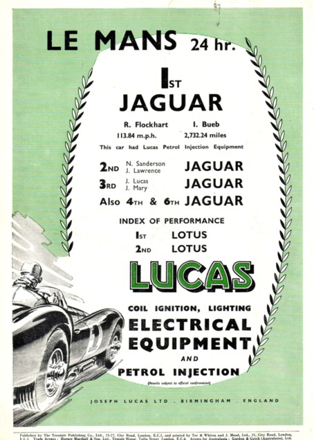
Throughout the 1950s, several manufacturers introduced their manifold injection systems for petrol engines. Lucas Industries had begun developing a fuel injection system in 1941 and by 1956 it was used in the Jaguar racing cars.[41] At the 1957 24 Hours of Le Mans, the 1st to 4th placed cars were Jaguar D-Type entries using a Lucas fuel injection system.[42] Also in 1957, General Motors introduced the Rochester Ramjet option, consisting of a fuel injection system for the V8 engine in the Chevrolet Corvette. During the 1960s, fuel injection systems were also produced by Hilborn,[43] SPICA[44] and Kugelfischer.

Up until this time, the fuel injection systems had used a mechanical control system. In 1957, the American Bendix Electrojector system was introduced, which used analogue electronics for the control system. The Electrojector was intended to be available for the Rambler Rebel mid-size car, however reliability problems meant that the fuel injection option was not offered.[45][46][47][48][49] In 1958, the Chrysler 300D, DeSoto Adventurer, Dodge D-500 and Plymouth Fury offered the Electrojector system, becoming the first cars known to use an electronic fuel injection (EFI) system.[50]

The Electrojector patents were subsequently sold to Bosch, who developed the Electrojector into the Bosch D-Jetronic.[51] The D-Jetronic was produced from 1967-1976 and first used on the VW 1600TL/E. The system was a speed/density system, using engine speed and intake manifold air density to calculate the amount of fuel to be injected. In 1974, Bosch introduced the K-Jetronic system, which used a continuous flow of fuel from the injectors (rather than the pulsed flow of the D-Jetronic system). K-Jetronic was a mechanical injection system, using a plunger actuated by the intake manifold pressure which then controlled the fuel flow to the injectors.[52]

Also in 1974, Bosch introduced the L-Jetronic system, a pulsed flow system which used an air flow meter to calculate the amount of fuel required. L-Jetronic was widely adopted on European cars during the 1970s and 1980s. As a system that uses electronically controlled fuel injectors which open and close to control the amount of fuel entering the engine, the L-Jetronic system uses the same basic principles as modern electronic fuel injection (EFI) systems.

1980s–present: digital electronics and common-rail injection

[edit]

Prior to 1979, the electronics in fuel injection systems used analogue electronics for the control system. The Bosch Motronic multi-point fuel injection system (also amongst the first systems where the ignition system is controlled by the same device as the fuel injection system) was the first mass-produced system to use digital electronics. The Ford EEC-III single-point fuel injection system, introduced in 1980, was another early digital fuel injection system.[53][54] These and other electronic manifold injection systems (using either port injection or throttle-body injection) became more widespread through the 1980s, and by the early 1990s they had replaced carburettors in most new petrol-engined cars sold in developed countries.

The aforementioned injection systems for petrol passenger car engines – except for the 1954–1959 Mercedes-Benz 300 SL – all used manifold injection (i.e. the injectors located at the intake ports or throttle body, instead of inside the combustion chamber). This began to change when the first mass-produced petrol direct injection system for passenger cars was a common rail system introduced in the 1997 Mitsubishi 6G74 V6 engine.[55][56] The first common-rail system for a passenger car diesel engine was the Fiat Multijet[broken anchor] straight-four engine,[57] introduced in the 1999 Alfa Romeo 156 1.9 JTD model. Since the 2010s, many petrol engines have switched to direct-injection (sometimes in combination with separate manifold injectors for each cylinder). Similarly, many modern diesel engines use a common-rail design.

Stratified charge injection was used in several petrol engines in the early 2000s, such as the Volkswagen 1.4 FSI engine introduced in 2000. However, the stratified charge systems were largely no longer in use by the late 2010s, due to increased exhaust emissions of NOx gasses and particulates, along with the increased cost and complexity of the systems.

See also

[edit]

References

[edit]
Revisions and contributorsEdit on WikipediaRead on Wikipedia
from Grokipedia
Fuel injection is a method of supplying to an by injecting it directly into the or intake ports under high pressure, allowing for precise control of the air- to optimize . This technology, controlled electronically by an engine control module (ECM) in modern systems, replaces earlier mechanisms and is essential for both spark-ignition engines—where mixes with air before ignition by a —and compression-ignition diesel engines, where ignites spontaneously due to high compression temperatures. Key components include pumps, injectors, sensors for monitoring parameters like air flow and position, and high-pressure lines to ensure atomization of the into fine droplets for complete burning. The development of fuel injection traces back to the late , when patented his compression-ignition engine in 1892, incorporating air-assisted mechanical fuel injection, using compressed air at around 500–1,000 psi to deliver and atomize for self-ignition without a spark. In gasoline engines, early mechanical systems emerged in the 1920s for and applications, but widespread adoption in automobiles began in the 1950s with systems like the Bosch mechanical injection used in models for superior performance. Electronic fuel injection (EFI), introduced in the 1970s and mandated in the U.S. by 1980s emissions standards, revolutionized the technology by enabling real-time adjustments via computers, leading to the phase-out of carburetors in production vehicles by 1990. Today, advanced variants like (GDI) and diesel injection dominate, driven by demands for higher efficiency and lower emissions. Fuel injection systems offer significant advantages over carburetors, including improved fuel economy through precise metering that avoids excess fuel, enhanced from better air-fuel distribution across cylinders, and reduced emissions by minimizing unburned hydrocarbons. They also eliminate induction system icing risks common in carbureted engines, provide smoother operation under varying loads, and support compatibility with alternative fuels. Common types for engines include throttle body injection (TBI) for single-point delivery, multi-point fuel injection (MPFI) with one injector per cylinder, and direct injection for in-cylinder mixing; diesel systems feature unit injectors for integrated pumping and injection, distributor pumps for smaller engines, and systems for electronic precision at high pressures. These innovations continue to evolve, with ongoing research focusing on ultra-high-pressure injection to further boost efficiency in hybrid and downsized engines.

Fundamentals

Basic principles

Fuel injection is the process of delivering precisely metered and atomized under high pressure into an , either directly into the or indirectly into the intake air stream to form an optimal air- mixture for . This method replaces mechanical mixing devices by using controlled injectors—often electronically in modern systems—to spray as a fine mist, enabling accurate control over fuel quantity and timing based on engine operating conditions. In spark-ignition engines, such as those powered by , fuel injection typically occurs in the port or manifold, where the fuel mixes with incoming air before entering the and being ignited by a . In compression-ignition engines, like diesel engines, fuel is injected directly into the hot in the , where it auto-ignites without a spark. Across both engine types, fuel injection supports efficient by ensuring the fuel is introduced at the precise moment and location needed for the engine cycle. Key benefits of fuel injection include enhanced through better air- ratio control, increased power output from optimized , and reduced emissions by minimizing unburned and excess pollutants. The basic components of a fuel injection system comprise a () to store the fuel, a to generate the required pressure, fuel lines to convey the pressurized , and injectors to release it into the . The atomization process is central to injection's effectiveness, where the nozzle forces through tiny orifices at high , breaking it into droplets typically 10 micrometers or smaller in for superior mixing with air and more complete . This high-pressure delivery, with modern diesel systems often exceeding 30,000 psi (2,000 bar) and systems typically 30–3,000 psi (2–200 bar), ensures rapid vaporization and even distribution, with pressurization and metering handled by the pump and controls as foundational steps.

Comparison to carburetion

Carburetors operate by mechanically mixing air and through the , where air accelerates through a narrowed , creating a that draws from a float chamber into the airstream. This passive process results in less precise control over the air- ratio compared to modern systems, as fuel delivery depends primarily on airflow velocity rather than active regulation. Fuel injection differs fundamentally from carburetion in its metering mechanism, employing sensors and actuators—electronic in modern systems—for precise fuel delivery tailored to engine demands, in contrast to the carburetor's reliance on passive vacuum and mechanical jets. This allows injection systems greater adaptability to varying operating conditions, such as changes in altitude, temperature, or load, by dynamically adjusting the fuel-air mixture, whereas carburetors maintain relatively fixed ratios that can lead to inefficiencies in non-ideal environments. Injection systems offer several operational advantages over carburetion, including superior cold-start performance through controlled enrichment that ensures reliable ignition without flooding, reduced risk of due to pressurized fuel delivery that prevents boiling in hot conditions, and elimination of by avoiding fuel evaporation in the intake manifold where moisture can freeze. The widespread transition from carburetors to fuel injection was driven by regulatory pressures for lower emissions, particularly following the 1970 Clean Air Act amendments, which imposed stricter standards that favored injection's precise metering for better efficiency and reduced pollutants like hydrocarbons and . For instance, throttle response in fuel injection is immediate upon demand, as electronic controls instantly adjust volume, whereas carbureted engines often exhibit a slight lag that requires an accelerator pump to squirt additional and compensate for the delay in venturi-induced flow.

System Functions

Pressurizing fuel

In fuel injection systems, pressurizing the is a critical function that ensures the is delivered at sufficient pressure to overcome engine-specific resistances, such as manifold in indirect systems or compression pressures in direct systems. This process begins with low-pressure pumps that supply from the tank at around 3-5 bar for indirect injection setups, while direct injection systems employ high-pressure pumps capable of generating up to 200 bar in applications and 1,000-2,500 bar in diesel configurations to achieve proper atomization and penetration. Fuel pumps are categorized by their pressure output and actuation method. Low-pressure pumps, typically electric and mounted in the fuel tank, provide consistent supply to prevent and maintain flow to high-pressure stages in direct injection engines. Mechanical pumps, often cam-driven and integrated with the engine, are used in some older or simpler systems to generate initial pressure synchronized with engine operation. High-pressure pumps, such as those in common-rail diesel systems, are usually mechanically actuated and boost pressure to extreme levels for direct injection, with designs incorporating pistons or plungers for precise volume displacement. Pressure regulation is achieved through components like relief valves, which vent excess pressure to avoid system damage, and accumulators, which store pressurized fuel to dampen pulsations and ensure steady delivery during injection events. In high-pressure systems, these regulators maintain operational limits, such as capping diesel rail pressures below 2,500 bar to protect injectors. Fuel properties significantly influence pressurization requirements; for instance, higher viscosity at lower temperatures increases the needed for pumping and can lead to reduced injection rates, while density variations affect the and flow under . In diesel direct injection, pressures of 1,000-2,500 bar are specifically required to counteract compression ratios up to 25:1, ensuring penetrates the effectively. This maintained enables accurate metering and injection timing in subsequent system functions.

Metering fuel

Fuel metering in fuel injection systems precisely controls the quantity of supplied to the engine to match varying operational demands, ensuring optimal efficiency and emissions control. Two main metering approaches are employed: time-based and volume-based. In time-based metering, common in electronic fuel injection systems, (PWM) varies the duration of the electrical signal to solenoid-operated injectors, thereby regulating the time the injector remains open and the amount of delivered. Volume-based metering, prevalent in mechanical systems, relies on physical displacement mechanisms, such as rotary or pumps, to deliver a fixed volume of per cycle regardless of pressure fluctuations. A key aspect of time-based metering is the in injectors, defined as the percentage of the injection cycle during which the injector is open; this open time directly determines the flow rate, with typical maximum duty cycles limited to around 80-90% to prevent overheating. Metering adjustments are influenced by several factors, including entering the , throttle position, load, and rotational speed (RPM), which sensors monitor to calculate the required volume for maintaining the desired air- mixture. Achieving precise metering is essential for target air-fuel ratios, such as the stoichiometric 14.7:1 by for engines, where complete occurs with minimal excess air or , while diesel engines operate at leaner ratios typically exceeding 18:1 to avoid formation and support efficient power output. Potential errors in metering arise from variations in , often due to changes, and injector from deposits; modern electronic systems compensate for density shifts using sensors to adjust widths, while fouling-induced flow reductions are addressed through adaptive strategies that monitor and correct over time. Consistent fuel pressure is a prerequisite for reliable metering, as fluctuations can alter flow rates independent of control signals.

Injecting fuel

The injecting phase delivers the metered volume of pressurized into the engine's or , where it atomizes into a fine spray for optimal air-fuel mixing. This process relies on specialized injectors that control the 's release, ensuring precise atomization synchronized with cycles. Fuel injectors vary by design to suit different types and performance needs. Pintle injectors feature a tapered needle or that lifts to form a diverging spray pattern, commonly used in port fuel injection systems for even distribution and reduced deposits. Hole-type injectors, prevalent in direct injection setups, employ multiple small orifices to produce discrete spray plumes, enabling targeted delivery into the . Piezoelectric injectors incorporate stack actuators that allow variable needle lift, facilitating multiple injections per cycle with rapid response times under 0.1 milliseconds for improved control. Injection timing coordinates the fuel delivery with position to maximize efficiency and minimize emissions. In mechanical systems, a -driven mechanism actuates the , aligning injection with the or compression . Modern electronic systems use the (ECU) to process signals from and position sensors, adjusting and timing dynamically based on load, speed, and temperature for sequential or phased injection. Key spray characteristics determine mixing quality and stability. The spray typically forms a cone angle of 10–30 degrees per plume in multi-hole designs, promoting broad coverage within the . Droplet sizes range from 10–100 microns in diameter, achieved through high-velocity shear at the , which enhances and reduces unburned hydrocarbons. , often 50–100 mm depending on and ambient conditions, ensures reaches the core airflow without excessive wall impingement. In direct injection systems, challenges include wall-wetting, where large droplets adhere to walls, leading to incomplete and increased particulate emissions. rates are influenced by fuel volatility and in- temperatures, with slower rates at low loads promoting pooling and oil dilution. To counter these, fuel is injected at pressures typically ranging from 10–30 MPa in systems to 100–250 MPa in diesel direct injection systems, atomizing it for rapid mixing with air.

Direct Injection Systems

Gasoline direct injection

Gasoline direct injection (GDI) systems deliver fuel directly into the combustion chamber of spark-ignition engines, typically during the intake or compression stroke, enabling precise control over the air-fuel mixture for optimized combustion. This direct placement allows for two primary operating modes: homogeneous charge mode, where fuel is injected early during the intake stroke to create a uniform mixture for high-load conditions, and stratified charge mode, which involves late injection near the end of the compression stroke to form a rich fuel pocket around the spark plug surrounded by leaner air, ideal for low-load efficiency. The stratified mode supports lean-burn operation, reducing throttling losses and improving part-load fuel economy. Key components include a high-pressure , often cam-driven, that generates pressures up to 200 bar to ensure proper atomization against pressures, and swirl injectors that impart rotational motion to the spray, promoting better mixing and charge motion within the chamber. These elements work with electronic controls to switch modes dynamically based on load and speed. GDI enables higher compression ratios, typically up to 12:1, due to the evaporative cooling effect of direct injection, which mitigates knock and boosts . Compared to port fuel injection, GDI improves by 10–15% through better control and reduced pumping losses. However, challenges arise from incomplete evaporation leading to wall impingement and higher particulate matter (PM) emissions, particularly during cold starts, necessitating gasoline particulate filters (GPFs) to capture and meet regulatory limits like Euro 6 standards. Widely introduced in the , GDI gained prominence with Mitsubishi's GDI , which achieved 7% better economy and significantly higher power output, and has since become standard in turbocharged engines for enhanced performance and emissions compliance.

Diesel direct injection

Diesel direct injection (DDI) involves injecting directly into the of a compression-ignition , where the air has been compressed to high temperatures, causing auto-ignition upon fuel introduction. This process relies on compression ratios typically ranging from 14:1 to 25:1, which generate cylinder temperatures of 800°F to 1200°F and pressures of 400 to 600 psi, enabling efficient combustion without spark ignition. A key feature of DDI systems is the use of multiple injections per cycle, such as pilot, main, and post-injections, which optimize phasing, reduce noise, and control emissions. Pilot injections occur early to soften ignition and minimize formation, while post-injections aid in particulate matter (PM) oxidation and aftertreatment regeneration. These strategies allow precise fuel delivery, improving overall engine performance compared to single-injection methods. DDI systems employ robust components, including electronically controlled injectors capable of operating at pressures exceeding 2,000 bar, often integrated with a common-rail delivery architecture for consistent high-pressure supply. These injectors feature and designs, such as piezo-actuated nozzles, to handle extreme conditions and enable rapid, multiple injection events with micrometer precision. The technology yields significant efficiency gains, with modern DDI engines achieving brake thermal efficiencies up to 40% in light-duty applications and 45% in heavy-duty ones, compared to approximately 30% in diesel systems due to reduced heat losses and better combustion control. However, DDI faces trade-offs in emissions, where higher combustion temperatures increase while incomplete mixing elevates PM; these are mitigated through (EGR) to lower peak temperatures and diesel particulate filters (DPF) to trap soot. DDI evolved prominently in the 1990s through the commercialization of common-rail systems by Bosch, which debuted in and provided unprecedented precise control over injection timing and quantity, revolutionizing performance and emissions compliance.

Common-rail systems

Common-rail systems represent a key advancement in injection technology, particularly for , where a shared high-pressure rail serves as a central accumulator that supplies pressurized to multiple injectors across the engine cylinders. This design decouples pressurization from the injection timing, allowing a high-pressure pump to maintain constant rail independently of engine speed or position, while electronic control units (ECUs) govern the precise activation of each injector. The rail typically operates at pressures ranging from 1,000 to 2,500 bar in standard applications, enabling finer atomization of for improved . Pressure control in common-rail systems relies on advanced actuators integrated into the injectors, such as solenoid valves for cost-effective operation or piezoelectric stacks for faster response times and higher precision. actuators use electromagnetic coils to open and close injector needles rapidly, supporting multiple injection events per cycle, while piezoelectric actuators leverage crystal deformation under voltage to achieve sub-millisecond control, minimizing fuel leakage and enabling injection durations as short as 100 microseconds. Rail pressure is regulated through a combination of pump metering and pressure relief valves, with closed-loop feedback from integrated sensors ensuring stability even under varying load conditions. The primary advantages of common-rail systems include enhanced flexibility in injection timing and rate, which allows for strategies like pilot, main, and post-injections to optimize , reduce noise through smoother pressure buildup, and lower emissions by better controlling and formation. Operating pressures up to 2,500 bar facilitate superior fuel atomization compared to earlier systems, contributing to up to 20% improvements in fuel economy and power output. Additionally, the decoupled design reduces mechanical stress on components, leading to quieter operation and extended durability. Evolution of common-rail systems accelerated in the 1990s, with pioneering commercial adoption in 1997 via the C 220 CDI model, which featured Bosch's initial 1,350 bar system for passenger cars. Subsequent developments pushed pressures to 2,000 bar by the mid-2000s for Euro 5 compliance, and modern iterations exceed 3,000 bar to meet stringent Euro 6 and Euro 7 emission standards, incorporating advanced materials like strengthened steels to handle the stresses. These enhancements have been driven by regulatory demands for reduced particulate matter and , with piezoelectric injectors becoming standard in high-end applications for finer control. Today, common-rail systems dominate nearly all modern diesel engines in light-duty vehicles, commercial trucks, and marine applications, powering over 90% of new diesel passenger cars globally due to their efficiency and compliance benefits. Emerging use in high-performance engines leverages similar rail architectures for precise fueling in turbocharged setups, such as those in premium sports cars, where pressures reach 200-350 bar to support stratified charge . A critical feature is the rail pressure sensor, which provides real-time feedback to the ECU for closed-loop control, compensating for pressure drops during injection and maintaining accuracy within 10 bar across operating conditions.

Indirect Injection Systems

Throttle-body injection

Throttle-body injection (TBI), also known as single-point injection, is an indirect injection system that delivers through one or two injectors mounted in the throttle body, spraying it directly into the manifold to mix with incoming air for distribution to all cylinders. This centralized approach atomizes upstream of the intake runners, allowing the air- mixture to be drawn into each cylinder during the intake stroke. The system operates by pulsing the injector(s) electronically, with the duration of each pulse—known as the injector on-time—determined by load, speed, and to achieve the optimal air- ratio. Unlike direct injection systems, TBI relies on manifold to transport the mixture, making it simpler and more akin to carburetion in its delivery mechanism. Key components of a TBI system include a low-pressure electric , typically delivering 9–13 psi (0.62–0.90 bar) to ensure adequate supply without requiring high-pressure lines, a to maintain consistent delivery to the injectors, and the throttle body assembly housing the injector(s), throttle valve, and idle air control valve. The (ECU) processes inputs from sensors such as the (TPS) for detecting accelerator pedal position, manifold absolute pressure () sensor for load measurement, and engine for cold-start enrichment. is drawn from the by the in-tank or external pump, filtered, and regulated before reaching the injector, which operates at a duty cycle up to 80% under full load. This setup provides basic closed-loop control via an for emissions compliance. TBI systems were widely applied in and vehicles as a cost-effective upgrade from carbureted engines, particularly in (GM) light-duty trucks and passenger cars. GM introduced its TBI system in production vehicles starting in 1987, equipping engines like the 4.3 L V6, 5.0 L V8, and 5.7 L V8 in models such as the trucks and Suburban, where it replaced carburetors to meet tightening emissions standards while minimizing manufacturing costs compared to multi-point systems. Early electronic TBI represented a transition from mechanical fuel injection designs, such as Bosch's K-Jetronic continuous injection system introduced in the , which used mechanical metering but paved the way for ECU-controlled variants. By the mid-, TBI had been phased out in favor of port injection in most GM applications, though it remains popular in aftermarket conversions for its simplicity and compatibility with older engine designs. Despite its advantages, TBI suffers from limitations in fuel distribution, as the single-point delivery can lead to uneven mixture quality across cylinders, especially in multi-cylinder engines with longer intake runners, resulting in variations in air-fuel ratios and potential wall wetting where fuel condenses on manifold walls. This lack of precision compared to per-cylinder injection reduces overall atomization efficiency and can cause higher emissions under transient conditions. In terms of fuel economy, TBI typically offers 5–10% improvement over equivalent carbureted systems due to better metering and reduced fuel puddling, but it is inferior to port fuel injection, which achieves more uniform distribution and up to an additional 10–15% efficiency gain through individualized injector control. These trade-offs made TBI a transitional technology, effective for emissions compliance in the 1980s but limited for high-performance or ultra-efficient modern applications.

Port fuel injection

Port fuel injection (PFI), also referred to as multi-point fuel injection (MPFI), is an system commonly employed in engines, where fuel is delivered directly into the port serving each . This method ensures that fuel mixes with incoming air before entering the , promoting thorough atomization and . Unlike single-point systems, PFI uses individual injectors positioned near the intake valves, allowing for precise per-cylinder fuel delivery that enhances overall and . In operation, each cylinder is equipped with one dedicated mounted at the intake port, which sprays into the airstream during the valve overlap period—when both intake and exhaust valves are partially open. This timing facilitates optimal vaporization on the heated intake port surfaces and thorough mixing with the intake charge, resulting in a homogeneous air- mixture that improves combustion stability. The (ECU) orchestrates sequential injection, pulsing the injectors in sync with the 's firing order based on inputs from sensors monitoring parameters like position, engine speed, and load. is supplied at moderate pressures, typically ranging from 3 to 6 bar, enabling reliable metering without the high stresses associated with direct injection. Key advantages of PFI include the generation of a more uniform air-fuel mixture across , which minimizes variations in and supports consistent power output. By injecting fuel outside the , PFI reduces wall-wetting—where adheres to walls—thereby lowering unburned emissions and improving fuel economy under part-load conditions. Additionally, the system's design aids easier cold starts, as the fuel benefits from the intake manifold's warmth to vaporize more readily, avoiding the pooling issues that can occur in colder direct injection setups. These benefits make PFI particularly suitable for naturally aspirated and moderate-performance engines. PFI systems are frequently integrated with direct injection in dual-injection configurations, especially in hybrid vehicles and efficiency-focused powertrains, where port injection handles low-load scenarios for better mixing while direct injection provides high-pressure boosts under demanding conditions. This combination optimizes delivery across operating ranges, enhancing overall and reducing knock tendencies. Regarding emissions, PFI produces lower particulate matter levels than direct injection due to reduced fuel impingement on combustion walls and better , though it may exhibit slightly higher consumption in high-power applications. PFI gained widespread adoption in the 1980s through advancements like the Bosch system, introduced in 1979, which combined electronic fuel injection with ignition control for improved precision and emissions compliance. By the , PFI remains a core technology in a substantial share of new vehicles—accounting for around 40% of U.S. sales as standalone systems as of 2021 and far more when including dual-injection setups—due to its reliability, cost-effectiveness, and compatibility with . As of model year 2023, standalone PFI has declined to approximately 27% with the rise of (GDI) to 73%.

Pre-chamber and hot-bulb systems

Pre-chamber systems represent an early form of indirect injection, where is sprayed into a small auxiliary chamber connected to the main by narrow orifices or passages. In this setup, the injected mixes with a portion of the to form a rich, ignitable mixture that auto-ignites due to the high temperatures from compression. The ensuing in the pre-chamber generates a jet that propagates rapidly into the main chamber, promoting more complete burning of the leaner air- mixture there. This divided-chamber design, also known as an IDI ( diesel) system, includes components such as the pre-chamber itself—often a swirl or divided chamber that induces for enhanced atomization—and operates at relatively lower injection pressures of 100–200 bar compared to direct injection methods. These systems offered key advantages over early direct injection designs, including smoother through the staged ignition process, which reduced noise and vibration, and easier cold starting by concentrating heat in the smaller pre-chamber volume for reliable ignition. A seminal example is the Ricardo pre-chamber, patented in 1931 by engineer , which utilized a swirl chamber to optimize air-fuel mixing and was licensed widely for high-speed diesel applications. This design powered numerous WWII-era vehicles, including military trucks and the Paxman RQ engine series adapted for armored and transport roles. Hot-bulb systems, another indirect variant prevalent in pre-1930s diesels, addressed starting challenges by incorporating a separate heated adjacent to the . Fuel was vaporized upon contact with the pre-heated bulb surface—initially warmed externally via for 10–15 minutes—allowing ignition without the need for high-pressure injection during startup. Common in stationary and marine engines running on heavy, low-grade oils, these systems provided simplicity and durability but required manual preheating. By the 1990s, pre-chamber and hot-bulb systems had largely declined in automotive and small-engine use, supplanted by direct injection's superior , reduced heat losses, and better emissions control enabled by high-pressure common-rail technology. However, variants persist in some large, low-speed marine and industrial engines where smooth operation and reliability outweigh efficiency gains from direct systems.

Control and Operation

Mechanical systems

Mechanical fuel injection systems represent an early engineering solution for delivering fuel into internal combustion engines without electronic controls, relying instead on physical components such as pumps and linkages to meter and time fuel delivery. These systems emerged as an advancement over carburetors, providing more precise fuel atomization under varying engine conditions, particularly in diesel applications where high-pressure injection is essential for compression ignition. Key types of mechanical fuel injection pumps include jerk pumps and distributor pumps. Jerk pumps, often configured in inline arrangements, feature individual plunger elements—one per engine —that generate high-pressure pulses to inject directly into the ; Bosch inline pumps, for instance, were widely used in diesel engines for their robust design and ability to handle multiple . Distributor pumps, such as the Bosch VE rotary type, employ a single rotating element to sequentially distribute pressurized to each via internal channels, offering a more compact alternative for smaller engines. Operation of these systems centers on camshaft-driven timing and mechanical governors for fuel metering. The pump's camshaft, synchronized with the engine crankshaft, actuates plungers or rotors to time injections precisely with the piston cycle, ensuring fuel is delivered at the optimal moment for combustion. Mechanical governors, typically centrifugal devices, adjust fuel volume by varying the stroke of the plungers or rotor position in response to engine speed, thereby maintaining stable operation across load changes without external feedback. These systems found primary applications in pre-1980s vehicles, aircraft engines, and heavy machinery, where reliability in harsh environments outweighed the need for fine-tuned adaptability. In automotive contexts, they powered diesel trucks and passenger cars requiring consistent performance; in , they supported radial engines during and early postwar models; and in heavy machinery like tractors and locomotives, they enabled efficient fuel use in stationary or low-speed operations. A notable example is the 1954 Mercedes-Benz 300SL, which utilized a mechanical direct injection system on its 3.0-liter inline-six engine to achieve 215 horsepower, marking a high-performance milestone for road cars at the time. Despite their durability, mechanical systems exhibit limitations, including reduced adaptability to rapid load variations due to the fixed mechanical linkages and governors, which can lead to suboptimal delivery under dynamic conditions. Additionally, their coarser atomization often results in incomplete , contributing to higher emissions of particulates and unburned hydrocarbons compared to later technologies. Maintenance of mechanical fuel injection systems is challenging, as pumps and linkages are prone to from high-pressure operation and exposure to contaminants, necessitating regular inspection and lubrication to prevent failures in plungers, cams, or control rods. Over time, helical grooves in jerk pumps can erode, and springs may fatigue, requiring periodic rebuilding or replacement to sustain .

Electronic fuel injection

Electronic fuel injection (EFI) systems rely on an (ECU), which serves as the central processor for managing fuel delivery in internal combustion engines. The ECU receives inputs from various sensors and uses pre-programmed algorithms to calculate the precise —the duration each fuel injector remains open—and the injection timing to optimize the air-fuel mixture under varying operating conditions. Fuel injectors are solenoid-actuated valves, with the solenoid coil energized through the injector's electrical connector. The specification "Terminal Count" on fuel injector listings refers to the number of electrical terminals (pins) on this connector, most commonly 2 (one for power and one for ground) to activate the solenoid coil, ensuring compatibility with the vehicle's wiring harness and connector. This digital control enables precise metering of fuel, improving efficiency, power output, and emissions control compared to earlier mechanical systems. Key sensors provide the ECU with real-time data essential for accurate fuel management. Mass air flow (MAF) or manifold absolute pressure (MAP) sensors measure incoming air volume or pressure to determine engine load and airflow rates, while the monitors engine speed (RPM) and position for synchronizing injection events. Oxygen (O2) sensors in the detect the proportion of unburned oxygen, offering feedback on the air-fuel ratio to enable adjustments for optimal . These sensors collectively allow the ECU to adapt fuel delivery dynamically to factors like acceleration, altitude, and temperature. In closed-loop operation, EFI systems use O2 sensor feedback to maintain the air-fuel mixture at or near the stoichiometric ratio of approximately 14.7:1 for engines, where (λ) equals 1.0, ensuring complete combustion and maximizing efficiency. The ECU continuously compares the measured value against the target and trims the accordingly, switching to open-loop mode only during transients like cold starts or wide-open to rely on preset maps. This feedback loop reduces emissions and enhances fuel economy by correcting deviations in real time. Advancements in EFI include integration of the , which enables seamless communication between the ECU and other vehicle modules, such as transmission and body controls, for coordinated operation and reduced wiring complexity. Predictive algorithms, often based on (MPC) or , anticipate transient conditions like rapid changes by forecasting air-fuel dynamics and preemptively adjusting injection parameters, minimizing torque disturbances and emissions spikes. Regulatory mandates, including II (OBD-II) requirements effective since 1996 for light-duty vehicles, compel EFI systems to monitor components like and fuel pumps for malfunctions, storing diagnostic trouble codes (DTCs) such as P0201-P0208 for injector circuit issues, often caused by chafed wiring harnesses, faulty connectors, or other electrical faults, or P0087 for low fuel rail . By 2025, updates incorporate for , analyzing data patterns to forecast failures in fuel delivery components before they impact performance. Diagnostics involve retrieving DTCs via standardized SAE protocols, allowing technicians to pinpoint faults in or pumps through resistance tests, checks, and waveform analysis.

History and Developments

Early inventions (1870s–1930s)

The development of fuel injection began in the late as engineers sought more efficient alternatives to carbureted spark-ignition engines, focusing on compression-ignition principles for heavier fuels. In 1872, American inventor patented an early (US 125,166) that used vaporized premixed with air in a reservoir, compressed, and ignited continuously by a pilot flame to maintain constant pressure during the power stroke, marking one of the first practical uses of fuel delivery in a piston engine. Later designs incorporated air-blast injection for liquid fuels. This system, while innovative, relied on a separate , limiting its efficiency and portability. A pivotal advancement came in 1890 with British engineer Herbert Akroyd Stuart's invention of the , which used pressurized fuel injection into a pre-heated vaporizing bulb to ignite heavy oils without spark, predating Diesel's work and enabling operation on low-grade fuels like paraffin. Akroyd Stuart's patents (British Nos. 7146 and 15994) described injection at the end of compression, achieving auto-ignition through from the hot bulb rather than pure compression alone, though the system required external heating for startup. In 1892, German engineer patented his compression-ignition engine, which injected fuel directly into highly (up to 25:1 ratio) at the end of the compression , igniting via the resulting high temperatures without a hot bulb or spark; his first successful prototype ran in 1897, demonstrating 26.2% . Diesel's design initially used air-assisted injection, where helped atomize the fuel, but it emphasized precise timing to optimize . By the and , fuel injection concepts extended to and heavy vehicles, with pressure carburetors emerging as a hybrid precursor to full injection systems in engines. These devices, such as early Bendix and models, used engine-driven pumps to pressurize (up to 5-10 psi) and inject it as a fine spray into the airstream, improving metering under varying altitudes and supercharging compared to float-type carburetors. In the diesel realm, German firm MAN developed mechanical fuel injection pumps in the early , featuring spring-loaded plungers for airless solid injection that delivered at pressures around 1000-4500 psi, enabling more compact direct-injection engines for marine and stationary use. A key milestone occurred in 1924 when MAN unveiled the first production diesel with a 4-cylinder direct-injection producing 45 hp, while introduced pre-chamber indirect-injection variants in the same era, injecting into a smaller auxiliary chamber for smoother and reduced noise in road vehicles. Despite these innovations, early fuel injection systems faced significant challenges, including imprecise metering due to inadequate atomization of viscous fuels, which led to incomplete , carbon buildup, and reduced efficiency. Starting difficulties were also prevalent, as cold engines required high compression or external preheating to achieve ignition temperatures, often necessitating auxiliary starting mechanisms like or electric heaters, which added complexity and bulk to designs. These issues limited early adoption to stationary and marine applications until improved pumps and materials addressed them in the late .

Mid-20th century advancements (1940s–1970s)

During , fuel injection played a critical role in advancing performance, particularly in German designs. The , introduced in 1944, featured direct fuel injection into the via atomizers, improving response and combustion efficiency in the fighter jet and marking the first operational production engine. A planned two-stage injection variant (004D) did not reach production. This direct injection approach allowed for precise fuel delivery under high-altitude conditions, contributing to the engine's axial-flow compressor capabilities and thrust output of approximately 8.8 kN. Post-war, mechanical direct injection transitioned to automotive applications, enhancing power in sports cars. The 1951 Goliath GP700, a front-wheel-drive two-stroke model, was one of the first production cars with gasoline direct fuel injection, using a Bosch system adapted from diesel technology, delivering around 25 hp from its 688 cc engine and enabling better efficiency in a compact design. This was followed by the 1954 Mercedes-Benz 300 SL Gullwing, the first production car with mechanical direct injection on a four-stroke engine, where the Bosch system boosted its 3.0-liter inline-six to 215 PS (about 212 hp), achieving a top speed of 250 km/h. In the United States, manifold injection emerged for emissions control; the 1965 Chevrolet Corvette offered an optional Rochester mechanical port fuel injection system, which improved fuel atomization and reduced hydrocarbon emissions to meet emerging California standards, producing up to 375 hp in high-performance variants. Diesel fuel injection also advanced in the 1950s, with indirect systems improving reliability in heavy-duty trucks. Cummins introduced its PT (pressure-time) fuel injection system in 1954, featuring a pre-chamber design that enhanced starting and reduced noise in engines like the 6BTA series used in commercial vehicles, achieving compression ratios around 16:1 for better torque delivery. By the 1970s, U.S. regulatory pressures accelerated the adoption of manifold electronic fuel injection (EFI). The 1970 Clean Air Act mandated 90% reductions in emissions by 1975, prompting automakers to shift from carburetors to EFI for precise air-fuel ratios; this led to systems like the 1975 Cadillac Seville's analog EFI, which cut CO emissions by up to 50% through closed-loop feedback.

Modern era (1980s–present)

The modern era of fuel injection began with the widespread adoption of digital electronic control systems in the , marking a shift from analog mechanical setups to integrated engine management. Bosch introduced the system in 1979, which combined fuel injection and ignition control in a single digital unit, initially applied to port fuel injection in gasoline engines for improved precision and efficiency. This technology proliferated in vehicles like models throughout the , enabling better air-fuel ratio management under varying loads. In diesel applications, the common-rail system emerged as a pivotal advancement, with Bosch's production version debuting in 1997 for passenger cars such as the , allowing independent control of injection timing, quantity, and multiple injections per cycle to reduce emissions and noise. Key developments in the 2000s and 2010s focused on direct injection to meet rising efficiency demands, with gasoline direct injection (GDI) seeing rapid proliferation among major manufacturers. Automakers including Ford, Volkswagen, General Motors, and BMW increasingly adopted GDI systems starting in the early 2000s, driven by their ability to enable stratified charge combustion for up to 15-20% better fuel economy compared to port injection. In the 2020s, hybrid powertrains advanced this further through dual-injection strategies, such as Toyota's D-4S system, which combines port and direct injection in models like the Camry Hybrid to optimize combustion across operating modes, reducing particulate emissions while maintaining power. By 2020, electronic fuel injection had achieved near-universal adoption, equipping over 95% of new light-duty vehicles globally as carbureted systems became obsolete. As of 2025, ongoing innovations include common-rail systems exceeding 3,500 bar for diesel and GDI pressures over 350 bar for gasoline engines, supporting Euro 7 standards and hybrid integrations that achieve up to 20% efficiency improvements in light-duty vehicles. Stricter emissions regulations accelerated innovations in injection pressures and controls. The Euro 6 standards, implemented in 2014, introduced particle number limits for GDI engines, prompting refinements in design to minimize formation. Subsequent real driving emissions (RDE) testing, phased in from 2017, further drove diesel common-rail systems to operate at pressures exceeding 3,000 bar, enabling finer fuel atomization and up to 10% reductions in real-world conditions. Looking ahead, fuel injection systems are evolving to support alternative fuels and . Hydrogen-compatible injectors, such as injection variants designed for manifold delivery, are under development to enable clean in internal combustion engines with near-zero CO2 output. In mild hybrid configurations, 48V systems integrate with existing fuel injection to provide assist during acceleration, yielding 10-15% fuel savings without full battery replacement. Emerging applications in electric vehicles with range extenders incorporate AI for predictive injection timing, optimizing small generators for up to 15% efficiency improvements in extended-range operation.

References

Add your contribution
Related Hubs
User Avatar
No comments yet.