Hubbry Logo
Test cardTest cardMain
Open search
Test card
Community hub
Test card
logo
8 pages, 0 posts
0 subscribers
Be the first to start a discussion here.
Contribute something
Test card
Test card
from Wikipedia
SMPTE color bars: common NTSC test pattern
PM5544: common PAL test pattern

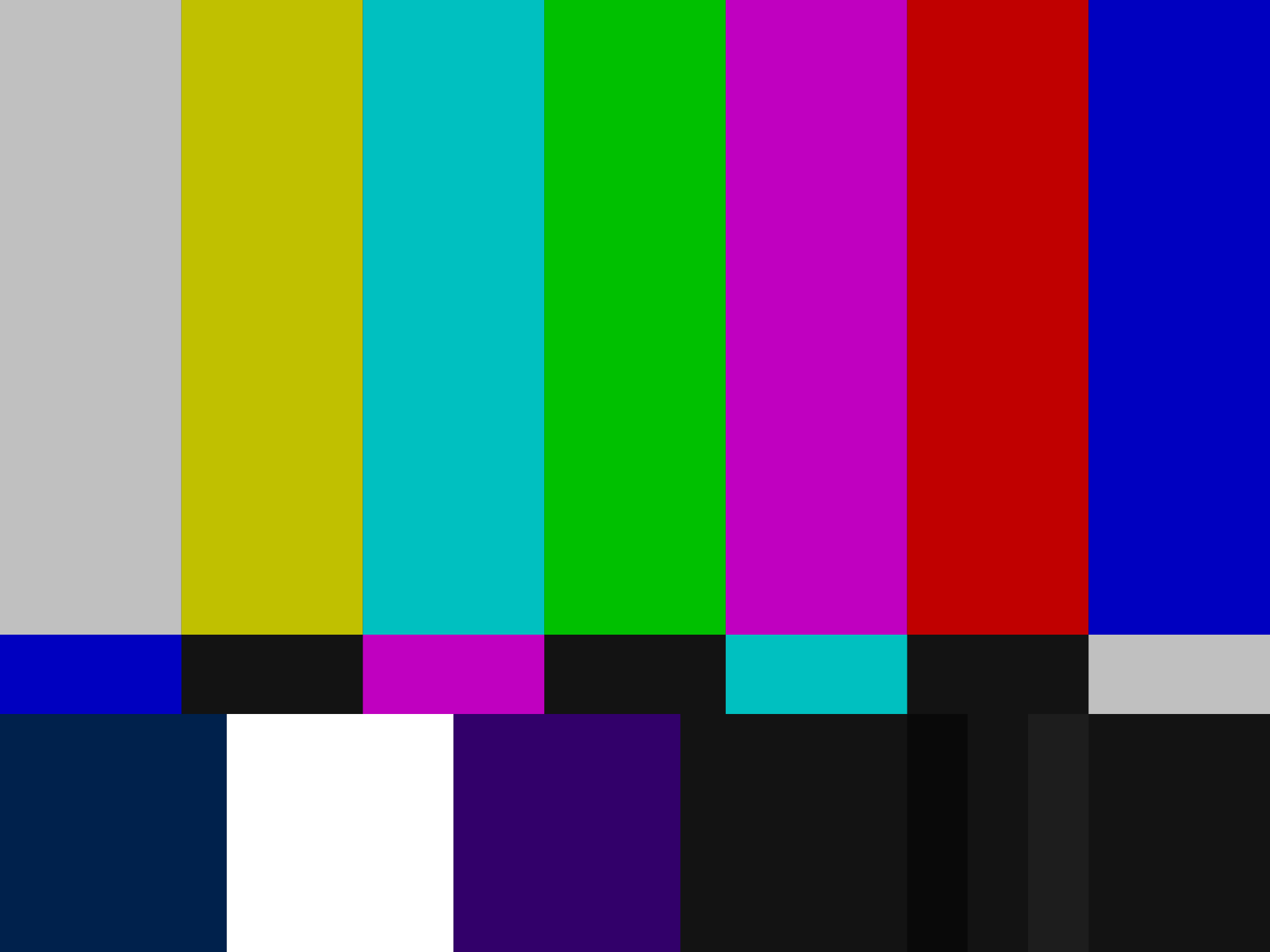
A test card, also known as a test pattern or start-up/closedown test, is a television test signal, typically broadcast at times when the transmitter is active but no program is being broadcast (often at sign-on and sign-off).[1]

Used since the earliest TV broadcasts, test cards were originally physical cards at which a television camera was pointed, allowing for simple adjustments of picture quality.[2] Such cards are still often used for calibration, alignment, and matching of cameras and camcorders. From the 1950s, test card images were built into monoscope tubes which freed up the use of TV cameras which would otherwise have to be rotated to continuously broadcast physical test cards during downtime hours.

Electronically generated test patterns, used for calibrating or troubleshooting the downstream signal path, were introduced in the late-1960s, and became commonly used from the 1970s and 80s. These are generated by test signal generators, which do not depend on the correct configuration (and presence) of a camera, and can also test for additional parameters such as correct color decoding, sync, frames per second, and frequency response.[3] These patterns are specially tailored to be used in conjunction with devices such as a vectorscope, allowing precise adjustments of image equipment.

The audio broadcast while test cards are shown is typically a sine wave tone, radio (if associated or affiliated with the television channel) or music (usually instrumental, though some also broadcast with jazz or popular music).

Digitally generated cards came later, associated with digital television, and add a few features specific of digital signals, like checking for error correction, chroma subsampling, aspect ratio signaling, surround sound, etc. More recently, the use of test cards has also expanded beyond television to other digital displays such as large LED walls and video projectors.[3]

Technical details

[edit]

Test cards typically contain a set of patterns to enable television cameras and receivers to be adjusted to show the picture correctly (see SMPTE color bars). Most modern test cards include a set of calibrated color bars which will produce a characteristic pattern of "dot landings" on a vectorscope, allowing chroma and tint to be precisely adjusted between generations of videotape or network feeds. SMPTE bars—and several other test cards—include analog black (a flat waveform at 7.5 IRE, or the NTSC setup level), full white (100 IRE), and a "sub-black", or "blacker-than-black" (at 0 IRE), which represents the lowest low-frequency transmission voltage permissible in NTSC broadcasts (though the negative excursions of the colorburst signal may go below 0 IRE). Between the color bars and proper adjustment of brightness and contrast controls to the limits of perception of the first sub-black bar, an analog receiver (or other equipment such as VTRs) can be adjusted to provide impressive fidelity.

Test cards have also been used to determine actual coverage contours for new television broadcasting antennas and/or networks. In preparation for the new commercial ITV service in the 1950s, the Independent Television Authority (ITA) tasked Belling & Lee, an Enfield-based British electronics company best known for inventing the Belling-Lee connector just over three decades earlier, with designing a series of Pilot Test Transmission test cards and slides[4] intended for potential viewers and DX-enthusiasts to test the ITA's new Band III VHF transmitter network that was designed with the assistance of the General Post Office (GPO), then the UK's government-run PTT agency. These test cards, some featuring the G9AED call sign assigned by the GPO for said transmissions, featured a squiggly line in a circle in the middle of the test card with an on-screen line gauge indicated in miles which was used as a guide to reveal the distance between the receiver, the (temporary) transmitter and a replicating landscape feature causing ghosting. Said test cards were mainly transmitted from temporary mobile transmitters attached to caravan trailers based at the predicted locations of the ITA's eventual main transmitters, such as Croydon, Lichfield, Emley Moor and Winter Hill.[5][6] Almost a decade later, the BBC started using a modified SMPTE monochrome test card radiating from the Crystal Palace transmitter to test its new UHF network which it eventually launched as BBC Two in 1964.

Test cards are also used in the broader context of video displays for concerts and live events. There are a variety of different test patterns, each testing a specific technical parameter: gradient monotone bars for testing brightness and color; a crosshatch pattern for aspect ratio, alignment, focus, and convergence; and a single-pixel border for over-scanning and dimensions.[3]

History

[edit]
The famous RCA Indian-head test pattern used mainly in North America from 1940 to the 1970s with its elements labelled, describing the use of each element in aligning a black & white analog TV receiver.
First RTF test card (1953) for the French 819-line TV system. Also used in French Algeria, with modifications also used by TMC in Monaco,[7] Telesaar in the Saar Protectorate,[8] and TVN in Chile[9]
A 1952 Philips TD1410U television set showing the optical monochrome Telefunken T05 test card.

Test cards are as old as TV broadcasts, with documented use by the BBC in the United Kingdom in its early 30-line mechanical Baird transmissions from 1934 and later on as simplified "tuning signals" shown before startup[10] as well as in Occupied France during World War II.[11] They evolved to include gratings for resolution testing, grids to assist with picture geometry adjustments, and grayscale for brightness and contrast adjustments. For example, all these elements can be seen in a Radiodiffusion-Télévision Française 819-line test card introduced in 1953.[11]

In North America, most test cards such as the famous Indian-head test pattern of the 1950s and 1960s have long since been relegated to history. The SMPTE color bars occasionally turn up, but with most North American broadcasters now following a 24-hour schedule, these too have become a rare sight.

With the introduction of color TV, electronically generated test cards were introduced. They are named after their generating equipment (ex: Grundig VG1000,[12][13] Philips PM5544,[14] Telefunken FuBK,[15] etc.), TV station (ex: BBC test card) or organization (ex: SMPTE color bars, EBU colour bars).

In developed countries such as Australia, Canada, the United Kingdom, and the United States, the financial imperatives of commercial television broadcasting mean that air-time is now typically filled with programmes and commercials (such as infomercials) 24 hours a day, and non-commercial broadcasters have to match this.

A late test card design, introduced in 2005 and fully adapted for HD, SD, 16:9 and 4:3 broadcasts, is defined on ITU-R Rec. BT.1729.[16] It offers markings specificity design to test format conversions, chroma sampling, etc.

Formerly a common sight, test cards are now only rarely seen outside of television studios, post-production, and distribution facilities. In particular, they are no longer intended to assist viewers in calibration of television sets. Several factors have led to their demise for this purpose:

  • Modern microcontroller-controlled analogue televisions rarely if ever need adjustment, so test cards are much less important than previously. Likewise, modern cameras and camcorders seldom need adjustment for technical accuracy, though they are often adjusted to compensate for scene light levels, and for various artistic effects.
  • Use of digital interconnect standards, such as CCIR 601 and SMPTE 292M, which operate without the non-linearities and other issues inherent to analog broadcasting, do not introduce color shifts or brightness changes; thus the requirement to detect and compensate for them using this reference signal has been virtually eliminated. (Compare with the obsolescence of stroboscopes as used to adjust the speed of record players.) On the other hand, digital test signal generators do include test signals which are intended to stress the digital interface, and many sophisticated generators allow the insertion of jitter, bit errors, and other pathological conditions that can cause a digital interface to fail.
  • Likewise, use of digital broadcasting standards, such as DVB and ATSC, eliminates the issues introduced by modulation and demodulation of analog signals.
  • Test cards including large circles were used to confirm the linearity of the set's deflection systems. As solid-state components replaced vacuum tubes in receiver deflection circuits, linearity adjustments were less frequently required (few newer sets have user-adjustable "VERT SIZE" and "VERT LIN" controls, for example). In LCD and other deflectionless displays, the linearity is a function of the display panel's manufacturing quality; for the display to work, the tolerances will already be far tighter than human perception.

For custom-designed video installations, such as LED displays in buildings or at live events, some test images are custom-made to fit the specific size and shape of the setup in question. These custom test images can also be an opportunity for the technicians to hide inside jokes for the crew to see while installing equipment for a show.[3]

Monoscope

[edit]
Close-up of the test-card image from a monoscope

Rather than physical test cards, which had to be televised using a camera, television stations often used a special purpose camera tube which had the test pattern painted on the inside screen of the tube. Each tube was only capable of generating the one test image, hence it was called a monoscope.

Monoscopes were similar in construction to an ordinary cathode-ray tube (CRT), only instead of displaying an image on its screen it scanned a built-in image. The monoscope contained a formed metal target in place of the phosphor coating at its "screen" end and as the electron beam scanned the target, rather than displaying an image, a varying electrical signal was produced generating a video signal from the etched pattern. Monoscope tubes had the advantage over test cards that a full TV camera was not needed, and the image was always properly framed and in focus. They fell out of use after the 1960s as they were not able to produce color images.

Other uses

[edit]
The test card bundled with the Links web browser since 2001

A lesser-known kind of test pattern is used for the calibration of photocopiers.[17][18] Photocopier test patterns are physical sheets that are photocopied, with the difference in the resulting photocopy revealing any tell-tale deviations or defects in the machine's ability to copy.

There are also test patterns kits and software developed specifically for many consumer electronics. The B&K Television Analyst was developed in the 1960s for testing monochrome TV sets in the NTSC standard and was later modified for European and Australian PAL standards. Among other uses, it consisted of a flying spot scanner on which a test pattern printed on a cellulose acetate slide was shown.[19]

When CRT monitors were still commonly used on personal computers, specific test patterns were created for proper calibration of such monitors in the cases whereby multimedia images could not be shown properly on said monitors.[20] Some VCD and DVD lens cleaner discs, such as the Kyowa Sonic lens cleaning kits from 1997–2001, also included test patterns as well.[21]

More recent examples include the THX Optimizer which can be accessed in the setup menu in almost every THX-certified DVD,[22][23] as well as the "HDR sRGB Graphics Test (400 nits)" and "Test Patterns" series available on Netflix[24] meant to test out streaming bandwidth on Internet-enabled devices,[25] especially on widescreen smart HDR TVs, 4K and 8K displays and also used to sync audio and video feeds, which can be affected, among other factors, by Bluetooth and Internet latency.[26]

Test patterns are also used to calibrate CCTV cameras and monitors,[27] as well as medical imaging displays and equipment for telemedicine and diagnostic purposes,[28] such as the SMPTE RP-133 medical diagnostic imaging test pattern specification for medical and surgical displays, created around 1983[29]–86;[30][31] as well as a later derivative called the TG18-QC test pattern created by the AAPM in 2001.[32][33] Test patterns to calibrate X-ray machines, in particular those manufactured by Leeds Test Objects in England, also exist as well.[34][35]

In numismatics

[edit]

Television has had such an impact in today's life that it has been the main motif for numerous collectors' coins and medals. One of the most recent examples is The 50 Years of Television commemorative coin minted on 9 March 2005, in Austria. The obverse of the coin shows the centre portion of the Telefunken T05 test card, while the reverse shows several milestones in the history of television.[36]

[edit]

The Philips Pattern and SMPTE color bars are widely recognised as one of the iconic popular culture symbols of the 1980s and 1990s in the markets where they were used. Numerous novelty and collectible items has been patterned after the famous test card, including wall clocks, bedsheets, wristwatches, and clothing. The character Sheldon Cooper on The Big Bang Theory wore tees with both patterns and a blogger identified the SMPTE shirt's use in more than a dozen episodes over the life of the series.[37]

The BBC Test Card F features throughout 2006-07 TV sci-fi detective series Life on Mars.[38][39]

Test card music

[edit]

In Britain, music rather than radio sound was usually played with the test card. The music played by the BBC, and afterwards ITV, was library music, which was licensed on more favourable terms for frequent use than commercially available alternatives.[40] Later, Channel 4 used UK library LPs from publishers like KPM, Joseph Weinberger and Ready Music.[41]

Until September 1955, the BBC used live playing 78 RPM commercial records as an audio background to the test cards. After that date, they switched to using recorded music on tape.[42] The following year, the BBC began to build up its own library of specially produced music for the half hour tapes – initially three tunes in similar style, followed by an identification sign (the three notes B-B-C played on celesta). ITV (which began its first trade transmissions in 1957) continued to use commercially available recordings until the late 1960s, when it also began to make specially produced tapes.[42]

For rights reasons, much of the music was recorded by light music orchestras in France and Germany, though sometimes by British musicians, or top international session players using pseudonyms, such as The Oscar Brandenburg Orchestra (an amalgamation of Neil Richardson, Alan Moorhouse and Johnny Pearson) or the Stuttgart Studio Orchestra.[43] Other composers and bandleaders commissioned for this type of work included Gordon Langford, Ernest Tomlinson. Roger Roger, Heinz Kiessling, Werner Tautz, Frank Chacksfield and Syd Dale.[44]

During the 1980s, the test card was seen less and less - it was pushed out first by Teletext pages and then by extended programme hours. The same tapes were used to accompany both the test card and Ceefax on BBC channels, but some fans argue that new tapes introduced after Ceefax became the norm in 1983 were less musically interesting.[42]

List of TV test cards

[edit]
A newly built television set undergoing image calibration using a test card at a Grundig factory in Nuremberg, West Germany (December 1959)
A 1940s-style "bullseye" test pattern exhibited at the Early Television Museum in Hilliard, Ohio (June 2022)

See also

[edit]

References

[edit]
[edit]
Revisions and contributorsEdit on WikipediaRead on Wikipedia
from Grokipedia
A test card, also known as a test pattern, is a static visual signal broadcast by stations to calibrate and align transmission equipment, as well as to assist viewers in adjusting their receivers for optimal picture quality. These patterns typically feature geometric shapes, color bars, ramps, and resolution charts designed to test aspects such as signal , contrast, focus, and color accuracy in analog systems. Originating in the , test cards emerged as television technology developed, with early examples used by broadcasters like the to help engineers align signals and dealers set up receivers. In the United States, the RCA Indian Head test pattern, introduced in 1939, became iconic for its depiction of a Native American headdress and was widely used for two decades to ensure proper tuning on black-and-white sets. By the mid-20th century, test cards were a staple during off-air hours, filling dead time when stations signed off—often late at night or before dawn—before the advent of 24-hour programming in the and . In , including the and , they played a key role in standardizing broadcasts, evolving from simple printed cards to electronic signals as was introduced in the 1960s. Notable test cards include the BBC's from 1967, the first color version transmitted in the UK featuring a young girl playing noughts and crosses, which became a cultural symbol and was used until the late 1990s. The PM5544, designed in 1966 by engineer Finn Hendil, offered an intricate circular pattern for precise calibration and was adopted internationally for PAL and systems. In , test cards broadcast from 1953 onward incorporated national symbols like the Swiss cross and were managed by until the shift to continuous broadcasting around 2005. These patterns not only ensured technical reliability but also evoked for the pre-digital era of television.

Definition and Purpose

Core Concept

A test card, also known as a test pattern, is a specialized visual signal in television broadcasting, consisting of a static or animated image designed to facilitate the testing and calibration of transmission, reception, and display equipment. These patterns provide a standardized reference that allows broadcasters and viewers to verify and adjust across the entire chain, from studio output to home receivers. The primary purposes of test cards include aligning key parameters such as , contrast and brightness levels, geometric accuracy (like and scanning ), resolution, and audio-video . For instance, elements like contrast wedges and resolution gratings enable precise adjustments to ensure optimal quality, while accompanying audio tones help sound levels and timing relative to the video. This is essential for maintaining consistent performance without relying on variable live content. Test cards function as reliable reference images that engineers and technicians use to diagnose and fine-tune broadcast systems during off-air periods or maintenance, revealing issues like or equipment misalignment in a controlled manner. They are typically static images featuring geometric shapes, ramps, and color bars to test fundamental display properties. This allows for comprehensive testing suited to baseline alignments.

Historical Role in Broadcasting

Test cards played a crucial role in early television broadcasting by filling gaps in programming schedules during non-broadcast hours, such as overnight periods or maintenance slots, ensuring that transmitters remained active and signal integrity was preserved. In the 1950s and 1960s, when television networks like the BBC in the UK operated limited daily hours—often signing off around midnight and resuming in the morning—test cards were routinely transmitted to occupy the airwaves, preventing complete silence or "dead air" that could disrupt equipment or viewer expectations. This practice was widespread across regions; for instance, U.S. stations displayed patterns like the Indian-head test card after late-night sign-offs, maintaining a modulated signal until morning programming began, with major networks providing approximately 12-13 hours of programming per day by the 1960s. Their importance extended to standardization efforts, promoting compatibility in and aiding by allowing engineers to verify transmission quality against established norms. In , broadcasters influenced the design of test cards to ensure consistent calibration across borders, facilitating the exchange of programs between countries with varying technical setups. In the United States, while the (FCC) did not mandate test patterns per se, stations utilized them during off-hours to align with technical operation rules, such as signal modulation requirements. This was essential in the analog era, where discrepancies in alignment could render international feeds unusable. Test cards also shaped the viewer experience by providing a steady, reassuring presence on screens during quiet periods, often accompanied by audio elements like time announcements or that conveyed reliability and utility. For many households in the through , tuning into a test card—such as the BBC's , broadcast daily from the late 1960s—signaled the end of the broadcast day, evoking a sense of closure while allowing families to adjust their sets for optimal viewing the next day. These patterns, sometimes featuring integrated clocks for precise timekeeping, served an educational function, informing late-night or early-morning audiences without demanding active engagement. As evolved from analog to digital formats in the late , test cards transitioned from an essential operational tool to a supplementary or archival element, largely supplanted by 24-hour programming and automated systems. By the , with networks expanding to continuous schedules—exemplified by the replacing daytime test cards with in 1983—their daily usage waned, though they persisted in maintenance roles until the early 2000s in regions like , where full shutdowns ended around 2005. This shift reflected broader technological advancements, reducing the need for manual calibration while preserving test cards as nostalgic symbols of television's formative years.

Technical Components

Visual Elements

Test cards incorporate a range of standardized visual elements to facilitate precise of television systems, ensuring accurate reproduction of , color, geometry, and focus. bars, typically arranged as a multi-step from to , enable adjustment of and contrast by assessing response and nonlinearity across gray levels, with steps corresponding to specific IRE units (e.g., 0 IRE for setup and 100 IRE for peak in ). Crosshatch grids, composed of evenly spaced horizontal and vertical lines, test geometric and color convergence by revealing distortions or misalignments in the display's beams or mapping. Circular or concentric ring patterns evaluate focus and , where ideally round shapes indicate proper ; any elongation or waviness signals issues in horizontal/vertical scanning or lens focus in projection systems. Text or numeral overlays, such as fine-printed characters or line pairs, measure horizontal and vertical resolution by determining the smallest discernible details, aiding sharpness adjustments. Color bars form a core component for hue and saturation calibration, with the SMPTE —prevalent in standards—featuring eight vertical bars in descending order: white (100% ), (88%), (78.7%), (59.7%), (43.4%), (28.1%), (19.1%), and (7.5% setup). These bars use 75% saturation levels to avoid overdriving the signal, allowing technicians to match gain and phase; for instance, and peaks should align at 100 IRE when properly adjusted. In PAL and systems, EBU color bars adopt a similar structure but with adjusted ratios for 100/0/75/0 amplitude (luma/chroma) to accommodate the phase-alternating modulation, prioritizing compatibility with colorimetry. Additional elements include pluge patterns for black-level setup, consisting of a reference black background with subtle bars at super-black (below setup), setup black, and slightly elevated gray (e.g., +4 IRE), where the middle bar should be just visible to prevent crushed shadows without lifting noise. Border signals, often subtle color ramps or tints around the image periphery, verify integrity and prevent clipping. Safe action areas, marked by rectangular overlays or guides (typically 90% of the active picture width and height), ensure critical content remains visible despite edge masking in consumer displays, as defined in ITU standards for productions. Element density varies by resolution to match system capabilities; for example, 480i patterns use coarser grids (e.g., 20-30 lines in crosshatch) suitable for standard-definition interlacing, while versions incorporate finer details (e.g., 50+ lines) and higher-frequency multiburst signals to test extended bandwidth without .

Generation Techniques

The generation of test card signals has evolved from mechanical approaches to advanced digital techniques, enabling precise control over visual patterns for and transmission testing. Mechanical methods dominated early television, utilizing rotating discs to scan patterns and produce video signals. In mechanical television systems, a Nipkow disc—a rotating metal plate with spirally arranged apertures—scanned the subject or pattern line by line, with light passing through the holes to modulate the signal based on intensity variations. Film loops, such as 16mm continuous strips containing test card images, were also employed to generate stable patterns for alignment in equipment, ensuring consistent output during pre-transmission setup. Electronic methods introduced greater precision through cathode ray tube (CRT) signal generators and digital synthesizers. CRT-based generators produced test patterns by modulating electron beams to create specific waveforms, allowing for adjustable and to simulate broadcast conditions. Digital synthesizers, employing direct digital synthesis (DDS) techniques, generated accurate sinusoidal and complex waveforms for test signals, offering fine resolution (e.g., 0.23 Hz tuning) and rapid switching for comprehensive system evaluation. Monoscope technology represented a specialized electronic approach, functioning as a dedicated CRT variant for fixed-image generation. The device featured an electron gun that emitted a focused beam, accelerated from a cathode at approximately -1200 V toward a metal target (typically aluminum) etched or printed with the test pattern, replacing the standard phosphor screen. As the beam scanned the target using a deflection yoke, areas of the pattern with higher secondary electron emission (0.3–0.7 μA) produced brighter signal outputs, while low-emission regions yielded darker levels; secondary electrons were collected by a final anode at +30 V to form the composite video signal. Controls for beam current, gain, and black level allowed fine-tuning, with the target connected via a central pip for output extraction. This setup delivered high-resolution patterns, such as over 450 lines, without mechanical wear. The transition to digital techniques has leveraged hardware like GPUs, FPGAs, and dedicated software for high-definition (HD) and ultra-high-definition (UHD) systems. FPGAs implement efficient test pattern generators using reconfigurable logic to produce patterns like color bars or grids in real-time, supporting formats up to 4K at 600 MHz pixel rates. GPUs enable software-based generation, such as network-controlled pattern creation for calibration, processing complex visuals at high frame rates. Signal encoding often occurs in color space, where luma (Y) and chroma (Cb, Cr) components are subsampled (e.g., 4:2:2 or ) to optimize bandwidth while preserving perceptual quality in video pipelines.

Historical Development

Origins in Early Television

In the pioneering era of mechanical television during the 1920s, inventors like experimented with rudimentary test patterns to verify signal transmission and image formation. Baird, working from his attic workshop in , , successfully transmitted simple outline images, including a , over short distances of two or three yards in April 1924 using a Nipkow disc-based system that scanned light through perforated rotating disks. These basic geometric shapes served as early calibration tools, helping to assess the mechanical scanning process amid the era's primitive technology, which relied on selenium-coated cells to convert light into electrical signals. Such patterns were essential for troubleshooting distortions in the low-resolution, flickering images produced by these systems, marking the initial steps toward standardized visual testing in television. By the 1930s, as television transitioned toward more structured broadcasts, the British Broadcasting Corporation (BBC) introduced formal tuning signals that evolved into the first recognized test cards. In 1934, during experimental 30-line transmissions using Baird's mechanical system, the BBC broadcast its inaugural tuning signal: a simple hollow black circle intersected by a horizontal line, designed to aid engineers in aligning cameras and receivers for optimal image fidelity. With the launch of the BBC's regular high-definition service from Alexandra Palace in November 1936, this evolved into a more defined tuning symbol by 1937—a circle with a vertical line and occasional "BBC Television Service" lettering—created hastily by engineer William Paffard using basic materials during a trade exhibition. These patterns drew influences from film projection testing, where physical charts were used to calibrate lenses and projectors, and from radio broadcasting's audio tone signals, adapting them to visual synchronization in the nascent medium. In the United States, adoption accelerated in the late 1930s amid pre-commercial experimentation. RCA introduced the iconic in 1939 at its facility, utilizing the TK-1 —a cathode ray tube with an etched metal plate—to generate the image without a camera, featuring a Native American profile encircled by resolution wedges, bars, and geometric grids for comprehensive equipment checks. This pattern addressed similar calibration needs as its British counterparts, testing focus, linearity, and contrast in black-and-white transmissions, and became a staple for field trials broadcast from stations like W2XBS in New York. Development faced significant interruptions from pre-war uncertainties and blackouts, particularly in . The suspended all television broadcasts on September 1, 1939—the day invaded —to repurpose the transmitter for jamming enemy signals and avoid aiding potential air raids, halting test card usage until a brief resumption in 1945 and full return in 1946. In the , while wartime restrictions limited civilian programming and shifted resources to military applications, limited test transmissions continued for technical refinement, though broader adoption of patterns like the Indian-head occurred post-war as commercial television expanded. These disruptions underscored the fragility of early television infrastructure amid geopolitical tensions.

Evolution Through Analog Eras

The transition to color broadcasting in the 1950s marked a significant in test card design, particularly in , where the standard was adopted for compatible color transmission. In 1953, the approved the NTSC color standard, enabling the introduction of color test patterns to calibrate receivers while maintaining with black-and-white sets. Early color bars, developed by engineers Norbert D. Larky and David D. Holmes at RCA Laboratories and patented in 1956 (filed 1951), provided a foundational electronic pattern for aligning hue, saturation, and , first appearing in broadcasts around 1954. Complementing these, the emerged as a key tool for assessing horizontal and vertical resolution in analog video systems, featuring wedge patterns ranging from 200 to 1000 TV lines to evaluate camera and display performance. By the 1960s and 1970s, global standardization efforts refined test cards for emerging color systems like PAL and in , emphasizing precision in geometric distortion, color fidelity, and resolution. The PM5544, an electronically generated pattern introduced in 1969 by engineers led by Finn Hendil, became widely adopted across for its comprehensive layout of circles, grids, and color ramps, facilitating transmitter and receiver alignment without physical slides. In the UK, the integrated a modified PM5544 variant from 1971 alongside its iconic (introduced 1967), while the Independent Broadcasting Authority used it initially for color setup. Paralleling this, the , standardized by the in the early 1970s, offered a simplified sequence tailored to PAL/SECAM , promoting interoperability among international broadcasters and replacing ad-hoc patterns. Refinements in the 1980s and 1990s addressed aspect ratio changes and signal integrity as broadcasting expanded to widescreen formats and continuous operation. Widescreen adaptations, such as the BBC's Test Card W (a 16:9 version of Test Card F introduced in the late 1990s), incorporated letterboxed elements and updated color bars to test 16:9 transmissions, ensuring compatibility with emerging high-definition precursors. Concurrently, Vertical Interval Test Signals (VITS), inserted into the non-visible lines of the video signal since the late 1970s but refined in the 1980s, enabled automated monitoring of chrominance phase, luminance nonlinearity, and differential gain during transmission, reducing reliance on full-screen patterns. The shift to 24/7 programming accelerated the phase-out of visible test cards, as stations like the BBC discontinued routine broadcasts by the mid-1980s in favor of automated diagnostics. Regional variations highlighted the decline of traditional test cards, particularly in the UK, where the launch of Channel 4 in 1982 introduced the IBA's ETP-1 electronic pattern for initial trade tests but adopted a policy minimizing visible test cards to support innovative, near-continuous scheduling. This reflected broader trends toward extended hours, with test cards persisting mainly for engineering purposes in some markets until the analog-to-digital switchover, completed in the UK by 2012 but effectively ending routine analog test signals around 2009.

Key Examples and Variations

Monoscope Patterns

Monoscope patterns refer to test signals generated using monoscope tubes, specialized cathode ray tubes that produce a fixed video image without requiring a traditional camera. These devices, developed in the late 1930s, feature a metal target plate printed or etched with a persistent pattern, such as using ink or light-sensitive materials that exhibit varying secondary emission properties when scanned by an electron beam. The beam sweeps across the target, generating an electrical output current proportional to the pattern's density variations, which is then amplified into a standard television signal for broadcast testing and calibration. This photoemissive process ensures a stable, repeatable image ideal for static test cards. A prominent example is the "Indian-head" pattern generated using RCA's 2F21 monoscope tube, introduced in 1939. This black-and-white pattern centers on a stylized profile of a Native American wearing a feathered headdress, flanked by geometric elements including radial lines, circular bullseyes for focus adjustment, resolution wedges for sharpness testing, and arrow-like alignment markers to verify geometric distortion and in broadcast displays. Widely adopted in the United States from the through the , it served as a benchmark for television alignment at stations, such as WABD in New York. The primary advantages of monoscope-generated patterns lay in their cost-effectiveness and simplicity for producing unchanging test images, as they bypassed the need for dedicated studio cameras, lighting, or film chains, thereby reducing equipment wear and operational expenses during off-air periods. Stations could integrate custom details like call signs into the tube's target plate for personalized use, enhancing practical alignment without additional hardware. However, monoscopes had inherent limitations, including gradual signal degradation from target aging—such as ink fading or leading to and instability—and their inability to adapt easily to emerging color standards or dynamic testing needs. By the , these tubes were phased out in favor of electronic signal generators and synthesized patterns, which offered greater versatility; the final commercial uses occurred in the early part of that decade as analog transitioned toward more advanced technologies.

Electronic and Color Test Cards

Electronic test cards advanced beyond precursor patterns by employing electronic signal generation to produce complex, color-inclusive visuals for comprehensive . These patterns emerged in the mid-20th century as standards proliferated, enabling precise evaluation of chroma, , and resolution in broadcast equipment. Unlike static optical slides, electronic designs allowed for standardized, repeatable tests across transmitters and receivers, facilitating international compatibility in analog color systems. The PM5544, developed in 1968-1969 by Danish engineer Finn Hendil at the Philips TV & Test Equipment laboratory in , , exemplifies early electronic color test patterns and became one of the most widely used in for PAL systems. It consists of a central circle segmented into radial color bursts arranged in a rainbow sequence to assess response and phase accuracy, complemented by surrounding linear grayscale steps for linearity and a grid of fine lines for sharpness evaluation. Additional elements, such as crosshatch patterns and frequency ramps, supported checks for geometric distortion and high-frequency response, while the overall design permitted subjective viewing to gauge picture fidelity in sets. Adaptations of the PM5544 were employed internationally, including variants for color signals, where it served as a test display card to calibrate broadcast chains with minor adjustments for local transmission parameters. Another notable example is the BBC's Test Card F, introduced in 1967 as the UK's first regular color test card. It depicted a young girl, , playing noughts and crosses with a , accompanied by various elements like color bars, grayscale ramps, and resolution charts. It was broadcast extensively until replaced in the early 1980s. The SMPTE RP 219 standard, published in 2002 by the Society of Motion Picture and Television Engineers, specifies a versatile color bar signal compatible with both high-definition and standard-definition formats. This pattern features vertical bars representing 100% saturated primaries (, , ), secondaries (, , ), neutral gray, and a simulated , alongside linear ramps for testing signal clipping, gain, and differential phase. Designed primarily for digital environments, it includes provisions for subcarrier frequencies and pluge pulses to verify setup levels and accuracy, making it a cornerstone for professional video equipment alignment.

Regional and Standard-Specific Patterns

North American Standards

In the United States, the RCA Indian-Head test pattern marked a key milestone in early standards, introduced in as a monoscope-based black-and-white tool that remained in use by many stations until the late . This pattern featured a central image of a Native American in headdress surrounded by resolution wedges, bars, and frequency markers to adjust focus, contrast, and linearity in analog receivers. The transition to color broadcasting in the introduced the , developed as an electronic test signal to verify and alignment in systems, with widespread adoption from the mid- onward. These vertical bars, consisting of seven color fields at 75% saturation plus a reference white and subcarrier phase indicator, became the for equipment setup and signal monitoring in North American studios and transmitters. With the shift to under in 1995, test patterns evolved to include digital equivalents like extended SMPTE bars, full-field color tests, and modulated signal streams for assessing compression artifacts and correction in ATSC 1.0 transmissions. For , introduced in 2017 and progressively deployed, regulatory test streams incorporate IP-based test content, bootstrap signals, and layered modulation patterns to evaluate mobile reception, HDR compatibility, and interference resilience during field trials. In Canada, the Canadian Broadcasting Corporation (CBC) adapted U.S. patterns for its NTSC-based system, employing EIA-standard resolution charts alongside the RCA Indian-Head monoscope in the monochrome era starting from CBC's inaugural broadcasts in 1952. The (FCC) enforced test signal mandates during the analog era through proof-of-performance rules under 47 CFR Part 73, requiring quarterly or semi-annual transmission of specified patterns—like grayscale ramps and multiburst signals—to verify signal fidelity and compliance with technical standards. These obligations transitioned to digital with the 2009 analog shutdown, where testing now emphasizes automated streams for spectrum efficiency and next-generation features, as outlined in FCC approvals for voluntary adoption. Notable implementations included Public Broadcasting Service (PBS) affiliates, which routinely aired or EIA resolution patterns overnight from the 1970s to the 1990s, often accompanied by tone signals during sign-off periods to facilitate engineer adjustments and maintain equipment alignment outside prime viewing hours.

European and International Variants

In , test card designs evolved to support the diverse analog color standards of PAL and , with the in the playing a pivotal role in developing a sequence of patterns for broadcast and viewer adjustment. The 's Test Card A, introduced shortly after for short daytime broadcasts, featured frequency gratings and a central circle to test resolution and . This was followed by Test Card B, which added an Ilford panchromatic test strip for contrast assessment, though no physical copies survive. Test Card C, launched in 1947 and used until the end of black-and-white television, initially had a 5:4 aspect ratio before shifting to 4:3 around 1949, incorporating various formats like cards, slides, and monoscopes, with centering arrows added in July 1958. Test Card D debuted in 1964 for 405-line systems, featuring graduated frequency gratings and later modifications including added dots in December 1965. Test Card E, introduced the same year for the 625-line BBC2 launch, mirrored D but with finer gratings. The iconic , rolled out in 1967 for color transmissions on 625 lines, included a color image of a girl and clown, becoming a staple on 1 from November 1969 and adopted by the Independent Broadcasting Authority (IBA) for its transmitters. Test Card J, an electronic update to F introduced in 1999 and used until at least 2013, incorporated additional elements like a green square and flashing dots for enhanced digital compatibility. Continental European broadcasters adapted similar electronic patterns to suit and PAL systems, emphasizing crosshatch grids and color circles for signal integrity. The PM5634, a specialized generator for transmissions, produced complex circle-based patterns to evaluate color separation, linearity, and in French and Eastern European networks during the 1970s and 1980s. In , public broadcasters ARD and employed the pattern from the mid-1970s onward as a successor to earlier designs, featuring a central crosshatch with surrounding color bars and wedges to calibrate resolution and geometric accuracy in PAL broadcasts. These patterns aligned with the (EBU) standards, such as the , which provided a baseline for 625-line PAL systems to ensure consistent color reproduction across member states. Internationally, test cards reflected colonial and technical influences from European models, particularly in and developing regions. Australia's (ABC) adopted a variant of the PM5544 circle pattern in the 1970s following the 1975 color rollout, utilizing crosshatch, color circles, and station identification to facilitate PAL adjustments nationwide. In , networks drew from designs, adapting BBC-style cards with grayscale ramps, color bars, and frequency gratings for their 1982 color transition under PAL-B/G, incorporating local station logos while maintaining core elements. These adaptations supported the expansion of television in post-colonial markets. Global harmonization efforts in the , led by the (ITU), promoted standardized test signals to aid developing broadcast infrastructures, particularly through CCIR (now ) recommendations like those in the 1986 Dubrovnik assembly for insertion test signals in 625-line systems. BT.470 outlined characteristics for conventional analog systems, including SECAM and PAL variants, recommending uniform test patterns to minimize interference and ensure in international signal exchanges. These guidelines facilitated adoption in emerging markets by providing scalable templates for color and testing without requiring proprietary equipment.

Modern and Alternative Applications

Digital Broadcasting and Computing

In digital television broadcasting, standards such as ATSC, , and employ test patterns adapted from analog eras but optimized for digital transmission, including full-field color bars to verify , color accuracy, and luminance levels across compressed streams. These patterns, generated electronically, ensure compliance with digital encoding like or HEVC, helping broadcasters maintain quality during and modulation processes. Post-2010 advancements introduced HDR-specific test patterns, such as calibration grids for systems under BT.2100, supporting formats like HDR-PQ and HDR-HLG used in , , and ISDB-T. For instance, BT.2111 defines color bar patterns in narrow and full ranges, with resolutions up to 8K (7680x4320), to align equipment for peak brightness exceeding 1000 nits and precise . These grids facilitate testing of dynamic metadata in HDR10+ and , ensuring consistent rendering across devices in global broadcasts. In computing contexts, test cards serve GPU and monitor calibration, with NVIDIA's control panel providing color bar patterns to adjust (e.g., full RGB 0-255) via outputs, preventing issues like crushed blacks in video playback. Tools like DisplayCAL enable precise profiling using colorimeters, generating custom patterns for gamma, , and uniformity checks on PC displays. test signals, often including SMPTE-style bars, are integrated into GPU diagnostics to validate bandwidth and artifact-free rendering at resolutions up to 4K. Advancements in UHD and 8K broadcasting incorporate dynamic metadata into test patterns, as seen in generators like the Aurora TPG-8K, which outputs 2.1 signals for AV-over-IP validation and high-resolution geometry alignment. Streaming services utilize software-generated cards; 's "Test Patterns" stream, available at 4K UHD, includes multipurpose charts for A/V sync, overscan detection, and coarse HDR calibration, downloadable for offline use. As of 2025, AI-driven auto-calibration integrates with test patterns to minimize manual adjustments, exemplified by Panasonic's W95B and Z95B TVs, which are Calman Ready for automated 3D LUT loading and real-time color tuning via the HCX Pro AI Processor. This reduces reliance on traditional cards by enabling device-side analysis of patterns for adaptive brightness and , enhancing accuracy in smart ecosystems.

Non-Broadcast Uses Including

Test patterns similar to those used in have found applications in diagnostics, where VGA and outputs display standardized images to verify hardware functionality and signal integrity. These patterns, often including color bars, grayscale ramps, and geometric shapes, help detect issues such as pixel defects, , or sync problems in monitors and GPUs. For instance, tools generate these visuals to test display connections and resolutions, ensuring proper output from graphics cards. In configurations, AMD's Eyefinity technology employs specific validation patterns to confirm seamless display spanning and alignment across multiple screens, aiding in hardware troubleshooting for professional setups. In printing and photography, CMYK test charts serve an analogous role to television test cards by providing benchmarks for color accuracy and reproduction fidelity during proofing processes. These charts feature arrays of color swatches, gradients, and registration marks printed in , , , and inks to calibrate presses and evaluate output against standardized profiles, such as those defined by ISO 12647. Photographers use similar charts, like the , to profile cameras and ensure consistent color rendering in digital workflows, mirroring the precision testing of broadcast signals. In home theater systems, visual test cards are frequently paired with audio test tones to calibrate both video and sound components holistically. Discs or digital files, such as those from or streaming services, display patterns like alongside pink noise or channel-specific sweeps to balance speaker levels, verify routing, and align audio-visual . This integrated approach ensures immersive performance in consumer setups, extending the diagnostic utility of test cards to multimedia environments.

Cultural and Media References

Test cards have appeared in several British television productions as symbols of mid-20th-century broadcasting and temporal displacement. In the series (2006–2007), the Test Card Girl, inspired by the central figure in , manifests as a haunting, otherworldly entity that interacts with the protagonist Sam Tyler, underscoring themes of psychological torment and . The character, played by Harriet Rogers in season 2, draws directly from the iconic 1967 test card featuring and her doll Bubbles, blending nostalgia with supernatural elements. Beyond scripted television, test cards have inspired nostalgic digital recreations and online communities, particularly on platforms like , where enthusiasts compile and remix vintage signals such as the BBC's and the RCA . These videos, often looping the patterns with period-appropriate music, have cultivated a since the early , celebrating the downtime of analog broadcasting as a relic of pre-24-hour TV. The , introduced by RCA in 1939, features prominently in these recreations for its stark black-and-white calibration elements, symbolizing the technical rituals of early U.S. television sign-offs. In and , test card motifs serve as emblems of analog and media transition. Additionally, the stage name "Test Card Girl" adopted by British Catherine Burgis reflects the enduring cultural resonance of test cards. These uses highlight test cards' role in evoking the quiet intervals of pre-digital media, often symbolizing pauses in cultural consumption.

Accompanying Test Card Music

The music broadcast alongside test cards during off-air periods primarily served to verify the audio fidelity of television receivers, allowing technicians and viewers to adjust sound systems while filling transmission gaps with non-intrusive content. Selections were typically drawn from works or music libraries to minimize costs and avoid issues, often featuring light orchestral or classical arrangements designed to entertain or soothe audiences without overpowering the test signal. In the , the paired —used from 1967 through the 1980s—with curated tapes of classical and starting in the mid-1950s, including half-hour compilations of orchestral pieces sourced from international libraries, such as French recordings like "La Foule." These playlists emphasized soothing, instrumental tracks to maintain viewer engagement during extended downtime, with the occasionally contributing electronic signatures, though conventional orchestral selections dominated. Other regions adopted similar approaches tailored to local broadcasting norms. , stations commonly played the followed by test patterns during sign-off hours from the 1950s to the 1970s, sometimes including stock music or periodic time signals. (ABC) transmissions in the 1970s featured ambient orchestral tracks, exemplified by recordings like the Rosetti Symphony in C Major on the Mace label, broadcast during evening test patterns to test both mono and audio capabilities. The legacy of test card music endures through dedicated compilations, with vinyl and releases emerging in the via labels like Apollo Sound, such as the "Test Card Music" series volumes 6 and 7, which anthologized rare tracks from and ITV archives. As of 2025, digital remasters of these collections are widely available on streaming platforms like , ensuring preservation and renewed interest in this niche of broadcast .

References

Add your contribution
Related Hubs
Contribute something
User Avatar
No comments yet.