Hubbry Logo
TurningTurningMain
Open search
Turning
Community hub
Turning
logo
8 pages, 0 posts
0 subscribers
Be the first to start a discussion here.
Turning
Turning
from Wikipedia
Roughing, or rough turning
Parting aluminium
Finish turning

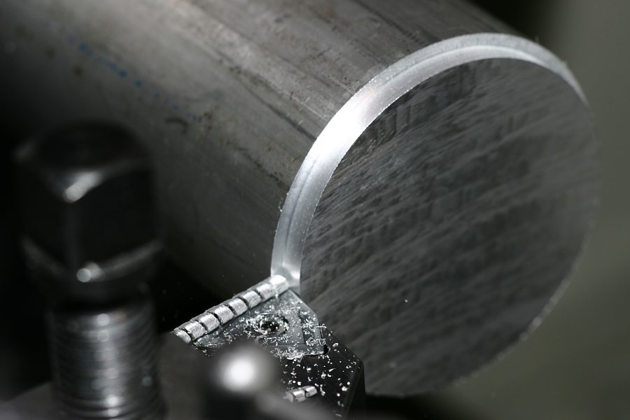
Turning is a machining process in which a cutting tool is held nearly stationary to cut a rotating workpiece. The cutting tool can be slowly moved back-and-forth, and in-and-out to cut cylindrical shapes, and flat surfaces on the workpiece. Turning is usually done with a lathe.

Usually the term "turning" is used for cutting external surfaces, and "boring" for internal surfaces, or holes. Thus the phrase "turning and boring" categorizes the larger family of processes known as lathing. Additionally, "facing" is cutting the ends of the workpiece, to create flat faces.

Turning is typically done with either a manual lathe, or a computer numerical control (CNC) lathe. With a manual lathe, an operator turns cranks to move the cutting tool. On a CNC lathe, the cutting tool is moved by a computer, controlling electric motors to follow a pre-programmed path. Early manual lathes could be used to produce complex geometric figures, even the platonic solids; though this is now usually done with CNC machines.

Different turning processes are typically carried out on a lathe, such as straight turning, taper turning, profiling or external grooving. Those types of turning processes can produce various shapes of materials such as straight, conical, curved, or grooved workpieces. In general, turning uses simple single-point cutting tools.

The waste metal cut off of the workpiece from turning operations is known as chips in North America, or swarf in Britain. In some areas they may be known as turnings.

A component that is made by turning is often called a turned part.

Turning operations

[edit]
Turning
Turning
The general process of turning involves rotating a workpiece while a single-point cutting tool is moved parallel to the axis of rotation.[1] Turning can be done on the external surface of the part as well as the internal surface (the process known as boring). The starting material is generally a workpiece generated by other processes such as casting, forging, extrusion, or drawing.
Tapered turning
Tapered turning produces a cylindrical shape that gradually decreases in diameter from one end to the other.[2]
Spherical generation
Spherical generation produces a spherical finished surface by turning a form around a fixed axis of revolution.[2]
Hard turning
Hard turning is performed on workpieces with a hardness greater than 45 Rockwell C. It is typically performed after the workpiece is heat treated. It is generally better than grinding for rough stock removal. However, grinding generally produces a better surface finish and can produce parts with greater dimensional accuracy.[3]
Boring
Cutting the inside surface of a hole or tube. A hole is usually first created by drilling, and then it is bored to enlarge it to its final diameter.
Drilling
Removes material from the inside of a workpiece with a drill bit. This process is the reverse of normal drilling operations in that the drill bit is held stationary and the workpiece is rotated. Reamers can also be used to enlarge a hole after it has been drilled.
Facing
Facing
Facing removes material from the end of a workpiece by moving the cutting tool perpendicular to the workpiece's axis of rotation.[1]
Grooving
External grooving
Face grooving
Grooving is the cutting of grooves to a specific depth in the workpiece. It can be performed on either internal or external surfaces, as well as on the face of the part. This is called "face grooving" or "trepanning."
Parting
"Parting off" or "cutoff" is performed by creating a deep groove, all the way through the workpiece, until the end falls off.
Knurling
Knurling
Pressing a serrated pattern onto the surface of a part to use as a hand grip or as a visual enhancement using a special purpose knurling tool.[2]
Threading
Screw threads can be turned on a lathe using a cutting tool with the shape of the thread. The axial movement of the cutting tool is linked to the rotation of the workpiece to create the thread's pitch. When this is performed on an outer surface, similar to turning, external threads are created. When performed on an internal surface, similar to boring, internal threads are created. This is referred to as "single point threading."
Alternately, taps and dies can be used to cut internal and external threads, respectively.[4]
Polygonal turning
Non-circular forms are machined.

Lathes

[edit]

Turning is usually performed on a lathe, which range in size from tabletop machines suitable for jewelry, to building-sized machines for manufacturing ship propeller shafts.

Workholding methods

[edit]
Collets
Chuck
Chucks grip a workpiece with movable jaws. They are less accurate than collets, but can hold a wider range of workpiece sizes.
Collet
Collets grip a workpiece by deforming around it. They grip over a larger surface than chucks, which puts less pressure on the workpiece, and center the workpiece better. Each collet has only a narrow range of workpiece diameters that it can deform enough to hold, so large sets of different collets are needed.
Faceplate
A faceplate is a plate that a workpiece is attached to, often with clamps or t-slot nuts. It is often used with a drive dog and mandrel. It can hold even more irregularly shaped workpieces than a chuck.
Centers
Centers are pointed cones, which support either a hollow tube workpiece, or a workpiece with holes drilled in its ends. Workpieces are ofter driven by a "dog".
Drive center
A drive center is a center which grips the workpiece strongly enough to drive it without the use of a dog. They often use hydraulic or spring-loaded teeth that bite into the end of workpieces. When supporting a workpiece only with centers, the entire outside of the workpiece may be machined in one setup.

Tooling

[edit]

Turning tooling usually cuts with a single point, as opposed to a drill bit or end mill which cut with several sharp edges. The angles around the sharp point are important, such as rake angle, side rake angle, cutting-edge angle, and relief angle. Additionally, the cutting point may have a nose radius which creates radii when cutting corners in the workpiece and extends the life of the tool tip, but increases machining forces.

The tool bit is held with a rigid tool holder during operation. CNC machines are typically able to switch tools automatically.

Dynamics of turning

[edit]

Forces

[edit]

Significant forces are required for turning operation, and must be accounted for in the design and selection of the machine tools, the workpiece holding, and any additional supports. A setup that is not strong enough may allow the workpiece to break free during operation, ruining the part being made, and endangering the operator. A setup that is not rigid enough will deform during operation, and create chatter when cutting, creating an undesirable surface finish, and inaccurate dimensions.

There are three principal forces in turning:

  • The cutting or tangential force acts downward on the tool tip and upwards on the workpiece upward. This is the force required to cut chips off of the workpiece. The force required to cut the material is called the specific cutting force, and depends on the material, cut depth, cut speed, and lubrication.
  • The axial or feed force acts in the longitudinal, or feed direction. This is the force necessary to feed the tool along the rotational axis of the workpiece.
  • The radial or thrust force acts in the radial direction and tends to push the tool out of the workpiece.

Speeds and feeds

[edit]

Speeds and feeds refer to the rotational speed that the workpiece is rotated at, and the feed speed that the tool is moved at. They are chosen based on the workpiece material, cutter material, setup rigidity, machine tool rigidity, spindle power, and whether coolant is used.

The rotational speed is measured in revolutions per minute (rpm).

The feed rate is the distance that the tool is fed into the workpiece per workpiece revolution. It is measured either as millimeters per revolution (mm/rev), or as inches per revolution (in/rev).

See also

[edit]

References

[edit]
[edit]
Revisions and contributorsEdit on WikipediaRead on Wikipedia
from Grokipedia
Turning is a subtractive process in which a single-point cutting tool removes from the surface of a rotating cylindrical workpiece mounted on a , producing parts with precise diameters and . This operation, one of the oldest and most versatile in , enables the creation of external features like shafts, pins, and bushings by controlling parameters such as spindle speed, feed rate, and depth of cut. The process typically involves securing the workpiece in a or between centers, rotating it at high speeds, and advancing the tool linearly along the axis to shear away excess , resulting in smooth finishes and tight tolerances. The origins of turning trace back to ancient civilizations, where rudimentary lathes powered by foot pedals or bows were used for as early as around 1300 BCE in , laying the foundation for shaping symmetrical objects. By the in the 18th and 19th centuries, metal turning emerged with the development of engine lathes, enabling of precision components for machinery and firearms; notable innovations include Thomas Blanchard's 1819 patent for an irregular-form wood-turning lathe, which influenced metalworking adaptations. The advent of computer (CNC) in the mid-20th century, originating from 1940s U.S. projects, revolutionized turning by automating tool paths and multi-axis movements for complex geometries. Key aspects of turning include its versatility across materials like metals, plastics, and composites, with operations varying by tool orientation and motion: straight turning reduces uniformly, taper turning creates conical shapes by offsetting the tool, and contour turning follows curved profiles for intricate forms. Additional variants encompass facing to square off ends, for features, and boring for internal s, often performed in sequence on the same . Modern CNC turning centers integrate milling, , and grooving capabilities, enhancing efficiency through automatic tool changers and high-speed spindles that minimize setup times. Turning finds widespread applications in industries requiring rotational components, such as automotive (e.g., crankshafts and axles), aerospace (e.g., shafts), and consumer goods (e.g., fasteners and fittings), where it offers cost-effective production of high-volume, precise parts compared to alternatives like grinding. Its ability to achieve surface finishes as fine as 0.8 micrometers and tolerances within 0.01 mm supports advanced , including hard turning of heat-treated steels to replace traditional grinding processes. Despite its advantages in speed and simplicity, turning demands careful consideration of cutting forces, , and use to maintain quality and safety in production environments.

Overview

Definition and Principles

Turning is a subtractive process in which a single-point cutting tool removes material from a rotating workpiece to produce cylindrical shapes and features. In this operation, the workpiece is secured and rotated about its central axis, while the stationary cutting tool is fed linearly into the material to shear away chips. This method is distinct from milling, where the tool rotates and the workpiece remains stationary, or , which creates holes by rotating a multi-point tool while feeding it axially into a stationary workpiece. The core principles of turning involve the controlled of the workpiece around a fixed axis, typically at speeds measured in (RPM), combined with precise linear movement of the tool parallel to the axis for longitudinal cuts or for facing operations. This relative motion generates shear forces that deform and remove material in the form of chips, enabling the creation of rotationally symmetric geometries. Key components include the spindle, which drives the workpiece ; the tool post, which positions and advances the cutting tool; and the , which provides a stable foundation to minimize vibrations and ensure alignment. Turning produces a range of geometric outcomes, such as external and internal diameters through straight turning, tapers via angled tool paths, and complex contours by varying tool motion. The efficiency of the process is often quantified by the material removal rate (MRR), which measures the volume of material excised per unit time. The MRR for turning is calculated as MRR=vc×f×ap\text{MRR} = v_c \times f \times a_p where vcv_c is the cutting speed, ff is the feed rate, and apa_p is the depth of cut; the cutting speed is vc=πDN/1000v_c = \pi D N / 1000 (with DD in mm, NN in rpm, vcv_c in m/min). This formula establishes the scale of productivity based on process parameters. Understanding turning operations requires familiarity with chip formation mechanics, where material ahead of the tool undergoes localized plastic deformation and shearing along a primary shear plane, resulting in continuous, discontinuous, or segmented chips depending on factors like ductility and cutting conditions. This shear process is fundamental to material removal but occurs without altering the basic rotational-linear of the operation.

Historical Development

The origins of turning can be traced back to ancient civilizations, where rudimentary were used for shaping and other materials. In around 1300 BCE, the earliest known form of the emerged as a two-person device, often called a pole lathe, in which one individual rotated the workpiece using a rope or pole while the other shaped it with a . This technique relied on manual to achieve basic in artifacts like furniture and vessels. By the Roman era, foot-powered were introduced, allowing a single operator to drive the rotation via a mechanism connected to a , which improved control and precision for and ornamental turning. Non-Western contributions also played a significant role in early turning development. In ancient China around 400 BCE, bow-driven lathes were employed to sharpen tools and weapons, enabling more efficient production in workshops and foreshadowing industrial-scale applications. These devices used a bowstring to impart oscillatory motion, adapting local materials and techniques to create symmetrical components for archery and metallurgy. The marked a pivotal shift toward mechanized precision in turning. In 1797, English engineer invented the slide rest lathe, incorporating a and adjustable tool post that allowed for accurate, repeatable cuts without manual guidance, revolutionizing the production of . Building on this, Scottish inventor introduced refinements in the , including improved planing attachments and self-acting mechanisms for lathes, which enhanced automation and supported in his workshops. These innovations standardized screw threads and enabled the manufacture of components with unprecedented accuracy. The 20th century brought further automation and control advancements to turning processes. Turret lathes, which featured a rotating tool turret for rapid tool changes, gained prominence in the early , evolving from 19th-century designs to support high-volume production of small parts like screws and fittings in American factories. The introduction of (NC) in the 1950s automated lathe operations using to direct tool paths, reducing manual intervention and improving consistency in and automotive . By the 1970s, computer numerical control (CNC) lathes emerged, with companies like pioneering microprocessor-based systems that allowed programmable operations, marking a transition from analog to digital precision turning. Material innovations complemented these mechanical advances. (HSS), developed in the early 1900s, permitted cutting at elevated speeds without losing hardness, significantly boosting productivity in operations compared to tools. In the 1920s, was developed and became viable for turning, offering superior wear resistance and enabling harder materials to be machined efficiently, though their widespread adoption accelerated post-World War II. In the from the 1980s onward, turning integrated with digital technologies for enhanced versatility. The incorporation of (CAD) and (CAM) software facilitated complex part programming, while multi-axis turning centers—often with live tooling and Y-axis capabilities—allowed simultaneous turning and milling on a single . Post-2000, automation trends in CNC turning have emphasized and Industry 4.0 integration, including collaborative robots for loading/unloading and AI-driven , which have reduced downtime and scaled production in sectors like automotive manufacturing.

Turning Operations

Basic Operations

The setup sequence for basic turning operations begins with securely mounting the workpiece in the lathe using appropriate workholding devices such as chucks or collets to ensure concentricity with the spindle axis. Next, the cutting tool is selected based on material compatibility and operation type, then installed in the tool holder and aligned parallel to the workpiece axis using indicators or dial test gauges to minimize runout. This alignment is critical for achieving uniform material removal and preventing taper or vibration during cuts. Once aligned, the process proceeds with roughing passes to remove bulk material at higher depths and feeds for efficiency, followed by finishing passes at lighter cuts to refine dimensions and surface quality. Primary operations in turning include straight turning, where the tool moves to the workpiece axis to reduce uniformly; facing, which creates a flat surface to the axis by feeding the tool across the end; chamfering, involving a 45-degree angled cut at edges for deburring or assembly fit; and grooving, which cuts narrow recesses into the surface for features like seals or part separation. These operations form the foundation of cylindrical shaping, typically performed sequentially starting with facing to square the ends before longitudinal turning. Key process variables in basic turning are depth of cut, which determines material removal per pass, and feed rate, which controls tool advancement per spindle revolution and directly affects by influencing the spacing of tool marks. Lower feed rates in finishing passes, often combined with shallower depths, can achieve high-precision tolerances such as ±0.001 inches, essential for components requiring tight fits. These variables balance productivity and quality, with excessive depths risking tool deflection and poor finishes. Chip control is vital for , as turning generates chips whose type—continuous (long, ribbon-like from ductile materials at high speeds) or discontinuous (segmented fragments from brittle materials or high feeds)—impacts and . Continuous chips can tangle around the workpiece or tool, obstructing flow and requiring breaks for clearance, thus reducing throughput; discontinuous chips, while easier to evacuate, may indicate suboptimal conditions like excessive heat buildup. Effective management through tool geometry or helps maintain consistent cuts and prevents damage. Basic turning operations differ between manual and automated setups, with manual processes relying on operator skill for tool positioning and feed control on engine lathes, while automated CNC turning uses programmed paths for precision and . Single-point setups employ one tool for sequential operations, suitable for simple parts, whereas multi-tool configurations on CNC turrets allow simultaneous or rapid tool changes for complex roughing and finishing in a single setup. This enables higher throughput in production environments without manual intervention.

Specialized Operations

Specialized turning operations extend beyond cylindrical profiles to produce threads, tapered surfaces, internal bores, irregular contours, and finishes on hardened materials, often requiring precise tool control and machine setups to achieve accuracy and surface integrity. Threading creates helical ridges on cylindrical or conical surfaces for fastening, with single-point threading being the primary method in lathes for both external and internal threads, where a single cutting edge progressively forms the thread profile in multiple passes synchronized with spindle rotation via the leadscrew. Single-point threading offers high precision for custom pitches and is suitable for small batches, using high-speed steel or carbide inserts ground to match thread standards like Unified or metric. In contrast, multi-point threading employs tools such as self-opening die heads or chasers with multiple cutting edges to form threads in fewer passes, accelerating production for external threads on larger volumes while maintaining synchronization through the lathe's gearing. Pitch is calculated as threads per inch (TPI) for imperial systems, determined by the leadscrew's TPI and change gear ratios to match the desired thread lead, ensuring the tool advances correctly per spindle revolution; for example, a 10 TPI leadscrew with appropriate gearing produces matching threads. Internal threading follows similar principles but uses boring bars with threading inserts, often requiring pre-drilled holes slightly larger than the minor diameter to accommodate chip evacuation. Boring enlarges pre-drilled holes to precise internal diameters, typically from 1 mm upward, using single-point tools mounted on bars that follow the workpiece's to remove material radially. Stability is critical due to the tool's cantilevered position, where excessive overhang—often exceeding four times the bar diameter—induces , leading to poor and dimensional inaccuracies; mitigation involves selecting the shortest possible bar, dampened adapters for overhangs over 4×D, and reduced cutting speeds (e.g., 90 m/min for ). Round inserts enhance edge strength for interrupted cuts or tough materials, while optimized clamping ensures flange contact to transmit effectively. Taper turning generates conical surfaces by offsetting the tool path relative to the workpiece axis, commonly using the compound method for short tapers, where the is swiveled to half the included taper , allowing the tool to feed diagonally across the face. For longer tapers, a taper attachment links the cross-slide to the via a guide bar set at the desired , ensuring consistent taper without manual adjustment and accommodating lengths up to the lathe's capacity. The taper θ is calculated as tan(θ) = (D - d) / (2L), where D is the larger , d the smaller , and L the taper , providing the half-angle for setup; this derives from the of the conical . Contouring and form turning produce non-cylindrical profiles by programming or manually guiding the tool along complex paths, often using CNC for curves, radii, or grooves that deviate from straight axial or radial motion. In manual lathes, templates or followers trace the desired shape, while CNC systems employ for precise multi-axis control, enabling intricate geometries like fillets or undercuts in one setup. , a form of surface texturing, enhances grip by embossing diamond, straight, or spiral patterns into the workpiece using paired or single wheels that displace material without removal, typically at low speeds (15–50 m/min) and shallow infeed (0.025–0.1 mm/rev) to avoid . Straddle tools with two dies provide uniform pressure for cylindrical sections, completing the pattern in 5–20 revolutions for diameters from 3 mm upward. Ring grooving is a specialized turning operation used to create circumferential grooves, such as those for O-rings, retaining rings, or seals, on external or internal surfaces of cylindrical workpieces. The process requires precise control to ensure proper fit and sealing performance. Key steps include: tool selection, where a grooving tool—typically carbide inserts for wear resistance or high-speed steel for custom shaping—is chosen to match the groove profile (e.g., square or round for O-ring grooves) and set at center height with minimal overhang to reduce vibration; setup, involving secure workpiece mounting in a chuck or between centers, alignment of the tool perpendicular to the axis, and application of coolant for heat management and chip evacuation; cutting parameters, utilizing reduced speeds (approximately half of standard turning speeds, e.g., 50-100 m/min depending on material) and light feeds (0.05-0.1 mm/rev) in multiple passes to achieve the desired depth without chatter, starting with roughing passes and finishing for surface quality; and measurement, employing calipers, micrometers, or the over-wires technique (placing wires in the groove and measuring over them to calculate depth via the formula: groove depth = (measured distance - wire diameter) / 2) to verify dimensions, ensuring the groove meets specifications like width (typically 1-3 mm) and depth (0.5-2 mm for standard O-rings). For internal ring grooves, a boring bar with integrated grooving insert is used, with careful attention to chip flow to prevent clogging. Hard turning machines components from hardened steels exceeding 45 HRC, leveraging cubic boron nitride (CBN) tools to achieve finishes comparable to grinding (around 0.4 μm ) without post-heat treatment. Emerging in the early 1980s and gaining prominence in the 1990s for automotive applications like and bearings, it offers advantages over grinding including 4–6 times higher material removal rates, up to 60% shorter cycle times, and 30% lower costs due to reduced setup and dry without coolants. Environmentally, it minimizes waste through recyclable chips and eliminates grinding sludge, while providing process flexibility for complex shapes on single machines.

Machining Equipment

Lathes and Configurations

Lathes are essential machine tools for turning operations, characterized by a rotating workpiece and a stationary cutting tool to remove material symmetrically around the axis of . Configurations vary from manual to automated systems, with designs optimized for precision, production , and workpiece dimensions. Key types include lathes for general-purpose manual work, turret lathes for repetitive tasks, CNC turning centers for complex multi-axis , Swiss-type lathes for small precision components, and vertical turning lathes for heavy, large parts. These machines share core structural elements but differ in and orientation to suit specific applications. The engine , a basic manual configuration, consists of a housing the spindle for workpiece rotation, a tailstock for supporting the opposite end, and a assembly that moves the cutting tool along the . It typically features capacities up to 20-inch swings over the bed, making it suitable for one-off or repair work requiring skilled operator control. The bed provides the foundational support, with ways guiding the carriage for precise longitudinal and transverse movements. Turret lathes enhance productivity through automatic tool indexing via a multi-faceted turret that holds multiple tools, allowing quick changes for repetitive production without manual repositioning. They are classified into capstan and ram types: capstan lathes feature a lighter turret mounted on a ram that slides on a for shorter strokes and higher speeds in lighter-duty work, while ram-type turret lathes use a heavier, more rigid setup where the ram moves back and forth on a clamped to the , supporting greater forces for robust . This design evolved from early slide rests to enable semi-automatic cycles in medium-volume . CNC turning centers represent the modern evolution of lathes, integrating for automated precision and versatility. Starting from basic 2-axis models focused on turning, they progressed to multi-axis configurations, such as those incorporating a Y-axis for off-center milling and live tooling for secondary operations like in a single setup. Contemporary 5-axis machines enable complex geometries on larger parts, reducing setups and improving efficiency in high-volume production. Swiss-type lathes, also known as sliding lathes, specialize in producing small, high-precision parts with diameters under 1 inch, where the slides through a guide bushing close to the cutting tool to minimize deflection. They are widely used in applications in medical devices, such as implants and surgical instruments, due to their ability to achieve tolerances as tight as ±0.0001 inches. Vertical turning lathes (VTLs) are configured with a horizontal spindle and vertical axis for large, heavy workpieces that would sag or be unstable in horizontal setups, such as components or ship propellers weighing up to 150 tons. The vertical orientation uses to aid workpiece stability, with the table rotating beneath overhead tools for efficient heavy-duty turning. Structurally, lathes incorporate bed ways—either flat for traditional stability in manual machines or inclined (slant-) in CNC models to facilitate chip evacuation and enhance rigidity during high-speed operations. Spindle bearings, often angular-contact bearings for handling combined radial and axial loads at high speeds or cylindrical roller types for supporting heavy radial loads, support high rotational speeds and axial loads while maintaining precision alignment. Many turning lathes utilize belt-driven spindles, where an external motor transmits power to the spindle via belts and pulleys, offering advantages such as quieter operation, reduced heat generation, and variable speed control suitable for precision machining. The lead screw, a threaded shaft parallel to the , drives the for synchronized feeds and threading by converting spindle rotation into . Power ratings span from 1 HP for benchtop models to 100 HP or more in industrial VTLs, scaling with machine size and cutting demands.

Workholding Methods

In turning operations, workholding methods are essential for securing the workpiece to the spindle or tailstock, minimizing deflection, , and inaccuracies while enabling precise material removal. These techniques must accommodate various workpiece geometries, materials, and lengths to maintain concentricity and . Common devices include chucks, centers, mandrels, and rests, each selected based on the part's characteristics and required tolerances. Chucks are versatile workholding devices mounted to the lathe headstock, gripping the workpiece externally with movable jaws. The 3-jaw self-centering chuck is widely used for round or hexagonal stock, as its jaws move simultaneously via a scroll plate to achieve rapid, concentric clamping without individual adjustments. In contrast, the 4-jaw independent chuck features jaws adjusted separately, allowing precise positioning for irregular or non-round shapes, such as squares or eccentric components, though setup time is longer. For high-precision applications requiring repeatability below 0.001 inches, collet chucks employ tapered collets that collapse radially to grip cylindrical stock with total indicated runout (TIR) as low as 0.0005 inches, making them ideal for small-diameter parts in production turning. For elongated workpieces, turning between centers provides stable support by mounting the part on conical centers at both the headstock and tailstock ends. A —a clamping device attached to the workpiece—drives rotation from the , while the tailstock center resists axial ; this method suits long shafts up to several feet, preventing sagging under cutting forces. The center is typically live, incorporating bearings to rotate with the workpiece and reduce at higher speeds, whereas a dead center in the tailstock remains stationary, requiring to avoid buildup from sliding contact and offering greater rigidity for heavy cuts. Expanding mandrels and steady rests address specific challenges in internal or extended holding. Expanding mandrels insert into the workpiece bore and inflate via a drawbolt mechanism to grip the internal uniformly, ideal for thin-walled or hollow parts where external clamping might cause , ensuring concentric turning of bores or external features. Steady rests, positioned along the bed, provide intermediate support with three adjustable rollers that contact the workpiece, damping vibrations and deflection in slender or overhung parts during longitudinal turning. Key considerations in workholding include control and material compatibility to preserve accuracy and prevent damage. Ideal , measured with a dial indicator on the workpiece surface, should be under 0.001 inches to avoid chatter and ensure dimensional tolerance in finish passes. For soft materials like aluminum, soft jaws—machined from low-durometer aluminum or mild —are preferred over hard jaws to conform to the part without marring surfaces or inducing stress concentrations. For non-ferrous or thin-walled components, magnetic and workholding offer alternatives to mechanical gripping, particularly in applications since the early . Magnetic chucks use electromagnetic or permanent rare-earth fields to hold parts across their entire surface, enabling five-sided access without clamps, while chucks create suction through porous tables or pods to secure non-magnetic materials like aluminum alloys, reducing setup time for complex geometries.

Tooling and Setup

Cutting Tools

Cutting tools for turning operations primarily consist of indexable inserts made from designed to withstand high temperatures, pressures, and forces during metal removal. (HSS) offers moderate around 60-65 HRC and good toughness but limited resistance up to 600°C, making it suitable for low-speed applications. , composed mainly of (WC) particles bonded with (Co), provides superior exceeding 90 HRA and resistance up to 1000°C, enabling higher cutting speeds in turning steels and cast irons. Cermets, combining and metallic phases, exhibit high wear resistance and low friction but lower and resistance compared to carbides. Ceramics, such as alumina-based composites, deliver exceptional above 90 HRA and resistance beyond 1200°C, ideal for high-speed finishing of heat-resistant alloys. Insert types are standardized under ISO designations, which specify , tolerance, clearance, and other features to optimize chip control and strength. Common shapes include the 80° (C-type) for versatile turning and the 60° triangle (T-type) for applications requiring strong chip breaking, such as roughing operations. For example, the CNMG designation indicates an 80° rhombic with 0° clearance, suitable for external turning with good edge strength. Tool wear in turning arises from interactions between the tool, chip, and workpiece, with primary mechanisms including crater wear, flank wear, and built-up edge (BUE). Crater wear manifests as a depression on the rake face due to chemical and high-temperature at the chip-tool interface. Flank wear occurs on the clearance face through abrasion by hard workpiece particles, gradually increasing and . BUE forms when workpiece material adheres to the cutting edge at low speeds, leading to poor and edge chipping upon detachment. Tool life, often defined as the duration until flank wear reaches 0.3 mm or crater depth compromises performance, is modeled by Taylor's equation: VTn=CVT^n = C where VV is cutting speed, TT is tool life, and nn and CC are empirical constants dependent on tool and workpiece. This seminal relation, derived from extensive experiments, highlights the inverse relationship between speed and , with nn typically 0.1-0.3 for tools. Coatings enhance tool performance by reducing , increasing , and improving . Titanium nitride (TiN) provides wear resistance and a visual indicator for edge inspection, while titanium aluminum nitride (TiAlN) offers superior oxidation resistance up to 900°C for high-temperature turning. Physical vapor deposition (PVD) applies thin (2-5 μm) coatings at 400-600°C, preserving sharp edges for finishing, whereas (CVD) deposits thicker (5-15 μm) layers at 700-1050°C for robust protection in roughing. Recent developments as of 2024 include advanced grades like Kennametal's KCU10B universal turning insert, offering improved performance across a broader range of materials. For machining high- materials (>45 HRC), polycrystalline (PCD) and cubic (CBN) inserts are preferred due to their extreme abrasion resistance and thermal stability. PCD, with near 9000 HV, excels in non- alloys like aluminum, while CBN (second hardest after ) handles hardened steels with minimal diffusion wear. In the , adoption of PCD and CBN surged post-1990s for finishing components and transmission gears, replacing grinding. Selection criteria emphasize matching material properties to workpiece , speed, and use to maximize life and surface quality.

Tool Holders and Geometry

Tool holders in turning operations are mechanical devices that securely mount cutting tools to the turret or tool post, ensuring stability and precise positioning during . Common types include straight shank holders, which feature a cylindrical shank clamped directly into the holder for simple, rigid setups in manual lathes, and indexable cartridge holders that incorporate modular cartridges for easy insertion replacement without altering the overall setup. Quick-change systems, such as those adhering to ISO standards or HSK (Hollow Shank Taper) configurations, enable rapid tool exchanges and enhanced in CNC turning centers; HSK holders, with their hollow 1:10 taper design, expand under spindle clamping to maintain grip at high speeds up to 40,000 RPM. In advanced CNC setups, Automatic Tool Changers (ATC) integrate with turning spindles to automate tool exchanges, allowing the machine to swap tools from a magazine without manual intervention, thereby reducing downtime and increasing efficiency in production environments. These ATC systems often utilize standardized tool holders like ISO or HSK for seamless compatibility with the spindle, supported by high-precision bearings to ensure stable operation during high-speed tool changes. The geometry of turning tools encompasses critical angles that optimize cutting performance, chip control, and tool life. The rake angle, defined as the angle between the tool's rake face and a plane perpendicular to the workpiece surface, is typically positive (5° to 20°) for ductile materials like aluminum to promote smooth chip flow and reduce cutting forces, whereas negative rake angles (-5° to -15°) are preferred for tough, abrasive materials such as hardened steels to increase edge strength and withstand higher temperatures. The relief angle, or clearance angle between the tool flank and workpiece, usually ranges from 5° to 15° to minimize friction and rubbing, preventing built-up edge formation and excessive heat. The lead angle, also called the side cutting edge angle, positions the cutting edge relative to the feed direction, typically 15° to 45° in turning, to distribute forces evenly across the edge, thereby reducing radial loads and improving stability during roughing operations. These geometric parameters directly influence cutting dynamics: a positive can lower power consumption by 10-25% through reduced requirements, facilitating higher feeds in soft materials, while negative rake enhances durability in interrupted cuts but increases demands. The nose radius at the tool tip, commonly 0.01 to 0.03 inches (0.25 to 0.8 mm) for finishing inserts, balances quality—smaller radii yield finer peaks and valleys for Ra values below 32 μin—with tool strength, as larger radii distribute stress but may cause chatter at low feeds. Lead angles greater than 0° further mitigate in heavy roughing by thinning the chip and lowering tangential forces. Setup procedures for tool holders emphasize precision to achieve optimal performance. Alignment of the tool tip to the spindle centerline, often verified using a dial indicator or tool setter, ensures accurate depth of cut and prevents uneven wear or dimensional errors exceeding 0.001 inches. Overhang—the distance from the holder clamp to the cutting tip—should be restricted to less than 4 times the shank to dampen vibrations and avoid chatter, which can degrade and accelerate tool failure; exceeding this ratio amplifies dynamic instability, particularly in slender workpieces. Since 2015, adjustable tool holders integrated with CNC systems have supported by allowing real-time geometry tweaks via sensors and actuators, optimizing parameters like rake or lead angles for varying material conditions in high-volume production.

Process Dynamics

Cutting Forces

In turning operations, the physical forces generated at the tool-workpiece interface are resolved into three main components: the tangential force (F_c, also called the cutting force), which is typically the largest component, often accounting for 50-70% of the total depending on conditions, and acts in the direction of cutting ; the radial force (F_p, or plow force), directed to the workpiece surface; and the axial force (F_f, or feed force), aligned with the feed direction. These components arise from shear deformation in the primary shear zone and along the tool-chip interface, and their relationships are graphically represented by Merchant's circle diagram, a foundational model for orthogonal cutting that approximates turning processes by illustrating force equilibrium and resolution. Cutting forces are measured using dynamometers, often piezoelectric or types, mounted between the tool holder and machine turret to capture dynamic and static triaxial data with high precision. For example, calculations for turning mild steel at a depth of cut around 3 mm and moderate feeds can yield tangential forces on the order of 2000 N. These measurements are essential for validating models and optimizing setups, as forces directly impact energy use and structural integrity. The tangential force dominates power consumption, given by the relation P=Fc×VP = F_c \times V (where PP is power, FcF_c is tangential force, and VV is cutting speed, with units adjusted for consistency, such as watts when FcF_c is in newtons and VV in meters per second). High forces contribute to tool and workpiece deflection, which can induce chatter—a self-excited that compromises surface and accelerates —while also straining components. Several factors influence magnitude: workpiece directly correlates with higher forces due to increased shear resistance, often rising 20-50% from soft to hardened states; tool sharpness affects , with dull edges increasing forces by up to 50% through greater plowing and rubbing; and mitigates at the interfaces, reducing overall forces by 20-50% compared to dry conditions. Tool geometry, such as , also modulates force distribution by altering chip flow and contact pressures. Cutting speed impacts force levels, with higher speeds generally lowering them via thermal softening of the . Since the early , finite element analysis (FEA) has become a standard method for predicting cutting forces in turning simulations, incorporating material models, friction coefficients, and thermal effects to forecast component magnitudes without physical trials. Additionally, optimizing cutting forces through parameter selection contributes to sustainable by reducing and minimizing , aligning with industry trends toward eco-friendly processes as of 2025.

Speeds and Feeds Calculations

Speeds and feeds calculations in turning operations determine the spindle speed, feed rate, and depth of cut to achieve efficient material removal while preserving tool life and surface quality. These parameters are selected based on workpiece , tool type, and capabilities to optimize , typically balancing higher speeds for faster cutting against the risk of accelerated . The spindle speed NN (in revolutions per minute, rpm) is calculated from the desired cutting speed VV (surface speed) and workpiece diameter DD. In metric units, the formula is: N=1000×Vπ×DN = \frac{1000 \times V}{\pi \times D} where VV is in meters per minute (m/min) and DD is in millimeters (mm). For example, with carbide tools, mild steel typically uses V=80150V = 80-150 m/min, while aluminum allows V=180300V = 180-300 m/min, enabling higher speeds for softer materials to increase throughput without excessive heat buildup. The feed rate ff (in millimeters per minute, mm/min) is then derived as f=fr×Nf = f_r \times N, where frf_r is the feed per revolution (typically 0.1-0.5 mm/rev for roughing, depending on tool and ). Depth of cut dd (or apa_p) is selected between 0.25-5 mm (0.01-0.2 inches), with shallower cuts (e.g., 0.25-1 mm) for finishing to improve and deeper cuts (up to 5 mm) for roughing harder materials like to maximize material removal rate (MRR). use adjusts these values, often increasing allowable VV by 20-50% through better heat dissipation and chip evacuation, particularly for . Optimization involves the Taylor tool , VTn=CV T^n = C, where TT is tool life in minutes, nn is a material-dependent exponent (0.1-0.3 for carbides), and CC is a constant derived from tool-workpiece pairs. This equation guides speed selection to achieve a target TT (e.g., 60 minutes), maximizing MRR = V×fr×dV \times f_r \times d under constraints like power limits and surface finish requirements. For instance, higher VV shortens TT exponentially, so speeds are tuned to minimize production cost per part. In Industry 4.0 contexts, AI-based systems extend these static calculations by real-time monitoring of forces, vibrations, and temperatures via sensors, dynamically adjusting feeds and speeds to optimize quality and efficiency. These systems use to predict and adapt parameters, thereby improving MRR and reducing defects in turning operations.

Applications and Considerations

Industrial Applications

In the , turning is widely employed to produce critical components such as shafts, pistons, crankshafts, and camshafts, enabling the high-precision fabrication required for and transmission systems. CNC turning supports high-volume production, facilitating efficient mass manufacturing of vehicles. Aerospace applications of turning focus on components, including blades, rotors, and shafts, where extreme precision is essential to withstand high temperatures, pressures, and vibrations. These parts often demand tolerances as tight as ±0.0001 inches (2.54 micrometers) to ensure structural and in jet engines and . Hard turning is particularly utilized for heat-treated alloys, allowing single-setup finishing of hardened materials like or to achieve surface finishes and dimensional accuracy without secondary grinding. In the medical sector, turning produces implants such as hip joints and dental prosthetics, as well as surgical tools like bone drills and needles, prioritizing and sterility. Swiss turning excels here for micro-features, enabling diameters under 1 mm (as small as 0.2 mm) and intricate geometries with tolerances down to 0.006 inches for drilled holes, supporting minimally invasive devices. Turning offers versatility across production scales, from of custom parts to high-volume runs, adapting to diverse materials and geometries without extensive retooling. For small batches, it provides cost savings over methods by eliminating expensive molds and dies, while achieving superior material utilization and lead times under weeks. In renewable energy, particularly wind power, large vertical turning lathes (VTLs) machine turbine hubs and nacelle components from heavy castings, handling diameters up to several meters since the 2010s to meet growing demands for offshore installations. This application enhances functional benefits like reduced downtime through precise fits and economic advantages via scalable production for gigawatt-scale farms.

Safety and Best Practices

Turning operations on lathes present several key hazards, including flying chips and debris, entanglement with rotating components, and failures induced by , which can lead to severe injuries such as amputations or impacts from ejected parts. Lathe operations contribute to machinery-related occupational injuries. Entanglement occurs when loose , , or jewelry contacts rotating spindles or chucks, potentially pulling operators into the machine, while flying chips—often hot and sharp—can cause burns, cuts, or eye injuries. hazards arise from unbalanced workpieces or worn tools, leading to chatter that may cause tool breakage or workpiece ejection, exacerbating risks during high-speed operations. Protective measures are essential to mitigate these risks, starting with machine guarding such as fixed or interlocked barriers around rotating parts like chucks and spindles to prevent access to hazard zones. Chip shields and transparent enclosures should cover the cutting area to deflect flying debris, while emergency stop buttons must be readily accessible for immediate shutdown in case of anomalies like unusual vibrations or noises. Personal protective equipment (PPE) includes safety glasses or face shields to guard against chips, hearing protection for noise levels often exceeding 85 dB, and snug-fitting clothing; however, gloves are prohibited near rotating elements to avoid entanglement. Proper workholding, such as secure chucks or collets, ensures workpiece stability and reduces vibration-related failures. Best practices for safe and efficient turning emphasize proactive monitoring and maintenance to prevent defects and accidents. Tool condition monitoring systems, utilizing sensors for , , or force, detect wear early to avoid catastrophic failures that could eject fragments or cause uncontrolled motion. application is critical to manage cutting zone temperatures, which can exceed 800°C and lead to thermal damage or fire risks; flood or through-tool reduces heat buildup, extends tool life, and controls chip formation. Pre-operation setup checks, including workpiece balance and alignment, minimize vibrations, while regular machine calibration ensures consistent performance. Ergonomic considerations, such as adjusting height to elbow level for upright posture and optimizing control layouts, reduce operator and musculoskeletal strain during prolonged sessions. In modern CNC turning, AI-enhanced systems provide advanced through real-time and , predicting and preventing tool-workpiece or tool-fixture impacts with over 95% accuracy in tested setups. practices focus on achieving target values below 1.6 μm Ra for functional parts, verified via profilometers or coordinate measuring machines (CMM) to inspect geometry and detect defects like chatter marks from improper feeds. These protocols not only enhance but also ensure defect-free outputs by integrating at key intervals.

References

Add your contribution
Related Hubs
User Avatar
No comments yet.