

Community hub
Recent from talks
Contribute something
Nothing was collected or created yet.
Check valve
View on WikipediaThis article needs additional citations for verification. (October 2017) |


A check valve, non-return valve, reflux valve, retention valve, foot valve, or one-way valve is a valve that normally allows fluid (liquid or gas) to flow through it in only one direction.[1]
Check valves are two-port valves, meaning they have two openings in the body, one for fluid to enter and the other for fluid to leave. There are various types of check valves used in a wide variety of applications. Check valves are often part of common household items. Although they are available in a wide range of sizes and costs, check valves generally are very small, simple, and inexpensive. Check valves work automatically and most are not controlled by a person or any external control; accordingly, most do not have any valve handle or stem. The bodies (external shells) of most check valves are made of plastic or metal.
An important concept in check valves is the cracking pressure which is the minimum differential upstream pressure between inlet and outlet at which the valve will operate. Typically the check valve is designed for and can therefore be specified for a specific cracking pressure.
Technical terminology
[edit]- Cracking pressure
- Refers to the minimum pressure differential needed between the inlet and outlet of the valve at which the first indication of flow occurs (steady stream of bubbles). Cracking pressure is also known as unseating head (pressure) or opening pressure.[2]
- Reseal pressure
- Refers to the pressure differential between the inlet and outlet of the valve during the closing process of the check valve, at which there is no visible leak rate. Reseal pressure is also known as sealing pressure,[3] seating head[4] (pressure) or closing pressure.[5]
- Back pressure
- a pressure higher at the outlet of a fitting than that at the inlet or a point upstream
Types
[edit]Ball check valve
[edit]

A ball check valve is a check valve in which the closing member, the movable part to block the flow, is a ball. In some ball check valves, the ball is spring-loaded to help keep it shut. For those designs without a spring, reverse flow is required to move the ball toward the seat and create a seal. The interior surface of the main seats of ball check valves are more or less conically tapered to guide the ball into the seat and form a positive seal when stopping reverse flow.
Ball check valves are often very small, simple, and cheap. They are commonly used in liquid or gel minipump dispenser spigots, spray devices, some rubber bulbs for pumping air, etc., manual air pumps and some other pumps, and refillable dispensing syringes. Although the balls are most often made of metal, they can be made of other materials; in some specialized cases out of highly durable or inert materials, such as sapphire. High-performance liquid chromatography pumps and similar high pressure applications commonly use small inlet and outlet ball check valves with balls of (artificial) ruby and seats made of sapphire[6] or both ball and seat of ruby,[7] for both hardness and chemical resistance. After prolonged use, such check valves can eventually wear out or the seat can develop a crack, requiring replacement. Therefore, such valves are made to be replaceable, sometimes placed in a small plastic body tightly fitted inside a metal fitting which can withstand high pressure and which is screwed into the pump head.[citation needed]
.jpg)
There are similar check valves where the disc is not a ball, but some other shape, such as a poppet energized by a spring. Ball check valves should not be confused with ball valves, which are a different type of valve in which a ball rotating on a pin acts as a controllable rotor to stop or direct flow.
Diaphragm check valve
[edit]A diaphragm check valve uses a flexing rubber diaphragm positioned to create a normally-closed valve. Pressure on the upstream side must be greater than the pressure on the downstream side by a certain amount, known as the pressure differential, for the check valve to open allowing flow. Once positive pressure stops, the diaphragm automatically flexes back to its original closed position.[8] This type is used in respirators (face masks) with an exhalation valve.
Swing check valve
[edit]A swing check valve (or tilting disc check valve) is a check valve in which the disc, the movable part to block the flow, swings on a hinge or trunnion, either onto the seat to block reverse flow or off the seat to allow forward flow. The seat opening cross-section may be perpendicular to the centerline between the two ports or at an angle. Although swing check valves can come in various sizes, large check valves are often swing check valves. A common issue caused by swing check valves is known as water hammer. This can occur when the swing check closes and the flow abruptly stops, causing a surge of pressure resulting in high velocity shock waves that act against the piping and valves, placing large stress on the metals and vibrations in the system. Undetected, water hammer can rupture pumps, valves, and pipes within the system.[9]
The flapper valve in a flush-toilet mechanism is an example of this type of valve. Tank pressure holding it closed is overcome by manual lift of the flapper. It then remains open until the tank drains and the flapper falls due to gravity. Another variation of this mechanism is the clapper valve, used in applications such firefighting and fire life safety systems. A hinged gate only remains open in the inflowing direction. The clapper valve often also has a spring that keeps the gate shut when there is no forward pressure. Another example is the backwater valve (for sanitary drainage system) that protects against flooding caused by return flow of sewage waters. Such risk occurs most often in sanitary drainage systems connected to combined sewerage systems and in rainwater drainage systems. It may be caused by intense rainfall, thaw or flood.
Butterfly check valve
[edit]
A butterfly check valve is a variant on the swing check valve, having two hinged flaps which act as check valves to prevent backwards flow. It should not be confused with the similarly named butterfly valve, which is used for flow regulation and does not have a one-way flow function.
Stop-check valve
[edit]A stop-check valve is a check valve with override control to stop flow regardless of flow direction or pressure. In addition to closing in response to backflow or insufficient forward pressure (normal check-valve behavior), it can also be deliberately shut by an external mechanism, thereby preventing any flow regardless of forward pressure.
Lift-check valve
[edit]A lift-check valve is a check valve in which the disc, sometimes called a lift, can be lifted up off its seat by higher pressure of inlet or upstream fluid to allow flow to the outlet or downstream side. A guide keeps motion of the disc on a vertical line, so the valve can later reseat properly. When the pressure is no longer higher, gravity or higher downstream pressure will cause the disc to lower onto its seat, shutting the valve to stop reverse flow.
In-line check valve
[edit]An in-line check valve is a check valve similar to the lift check valve. However, this valve generally has a spring that will 'lift' when there is pressure on the upstream side of the valve. The pressure needed on the upstream side of the valve to overcome the spring tension is called the 'cracking pressure'. When the pressure going through the valve goes below the cracking pressure, the spring will close the valve to prevent back-flow in the process.[10]
Duckbill valve
[edit]A duckbill valve is a check valve in which flow proceeds through a soft tube that protrudes into the downstream side. Back-pressure collapses this tube, cutting off flow.
Pneumatic non-return valve
[edit]Pneumatic non-return valves provide the ability to lock the valve, hence preventing flow in either direction. This may be used if for example a site with hazardous materials should be protected from flood water, however it is also important that the materials can't leak, for example during transfer between vessels.
Reed valve
[edit]A reed valve is a check valve formed by a flexible flat sheet that seals an orifice plate. The cracking pressure is very low, the moving part has low mass allowing rapid operation, the flow resistance is moderate, and the seal improves with back pressure. These are commonly found in two stroke internal combustion engines as the air intake valve for the crankcase volume and in air compressors as both intake and exhaust valves for the cylinder(s). Although reed valves are typically used for gasses rather than liquids, the Autotrol brand of water treatment control valves are designed as a set of reed valves taking advantage of the sealing characteristic, selectively forcing open some of the reeds to establish a flow path.[11]
Flow check
[edit]A flow check is a check valve used in hydronic heating and cooling systems to prevent unwanted passive gravity flow. A flow check is a simple flow lifted gravity closed heavy metal stopper designed for low flow resistance, many decades of continuous service, and to self-clean the fine particulates commonly found in hydronic systems from the sealing surfaces. To accomplish self cleaning, the stopper is typically not conical. A circular recess in a weight that fits over a matching narrow ridge at the rim of an orifice is a common design. The application inherently tolerates a modest reverse leakage rate, a perfect seal is not required. A flow check has an operating screw to allow the valve to be held open, the opposite of the control on a stop-check valve, as an aide for filling the system and for purging air from the system.[12]
Multiple valves
[edit]Multiple check valves can be connected in series. For example, a double check valve is often used as a backflow prevention device to keep potentially contaminated water from siphoning back into municipal water supply lines. There are also double ball check valves in which there are two ball/seat combinations sequentially in the same body to ensure positive leak-tight shutoff when blocking reverse flow; and piston check valves, wafer check valves, and ball-and-cone check valves.
Applications
[edit]Pumps
[edit]
Check valves are often used with some types of pumps. Piston-driven and diaphragm pumps such as metering pumps and pumps for chromatography commonly use inlet and outlet ball check valves. These valves often look like small cylinders attached to the pump head on the inlet and outlet lines. Many similar pump-like mechanisms for moving volumes of fluids around use check valves such as ball check valves. The feed pumps or injectors which supply water to steam boilers are fitted with check valves to prevent back-flow.
Check valves are also used in the pumps that supply water to water slides. The water to the slide flows through a pipe which doubles as the tower holding the steps to the slide. When the facility with the slide closes for the night, the check valve stops the flow of water through the pipe; when the facility reopens for the next day, the valve is opened and the flow restarts, making the slide ready for use again.[13]
Industrial processes
[edit]Check valves are used in many fluid systems such as those in chemical and power plants, and in many other industrial processes.
Typical applications in the nuclear industry are feed water control systems, dump lines, make-up water, miscellaneous process systems, N2 systems, and monitoring and sampling systems.[14] In aircraft and aerospace, check valves are used where high vibration, large temperature extremes and corrosive fluids are present. For example, spacecraft and launch vehicle propulsion propellant control for reaction control systems (RCS) and Attitude Control Systems (ACS) and aircraft hydraulic systems.[15][16]
Check valves are also often used when multiple gases are mixed into one gas stream. A check valve is installed on each of the individual gas streams to prevent mixing of the gases in the original source. For example, if a fuel and an oxidizer are to be mixed, then check valves will normally be used on both the fuel and oxidizer sources to ensure that the original gas cylinders remain pure and therefore nonflammable.
In 2010, NASA's Jet Propulsion Laboratory slightly modified a simple check valve design with the intention to store liquid samples indicative to life on Mars in separate reservoirs of the device without fear of cross contamination.[17]
Domestic use
[edit]When a sanitary potable water supply is plumbed to an unsanitary system, for example lawn sprinklers, a dish washer or a washing machine, a check valve called a backflow preventer is used to prevent contaminated water from re-entering the domestic water supply.
Some types of irrigation sprinklers and drip irrigation emitters have small check valves built into them to keep the lines from draining when the system is shut off.
Check valves used in domestic heating systems to prevent vertical convection, especially in combination with solar thermal installations, also are called gravity brakes.
Rainwater harvesting systems that are plumbed into the main water supply of a utility provider may be required to have one or more check valves fitted to prevent contamination of the primary supply by rainwater.
Hydraulic jacks use ball check valves to build pressure on the lifting side of the jack.
Check valves are commonly used in inflatables, such as toys, mattresses and boats. This allows the object to be inflated without continuous or uninterrupted air pressure.
History
[edit]Frank P. Cotter developed a "simple self sealing check valve, adapted to be connected in the pipe connections without requiring special fittings and which may be readily opened for inspection or repair" 1907 (U.S. patent 865,631).
Nikola Tesla invented a deceptively simple one-way valve for fluids in 1916, called a Tesla valve. It was patented in 1920 (U.S. patent 1,329,559).
Images
[edit]-
 Hastelloy check valves
 -
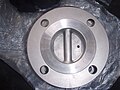
 Stainless steel wafer check valve
 -
 Inconel check valve
 -
 Inside view of a tilting disc inconel check valve
 -
 Flanged nozzle inconel check valve or axial check valve
 -
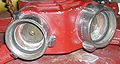 This Siamese clappered inlet allows one or two inputs into a deluge gun.
 -
 Inside hastelloy check valve, wafer configuration
 -
 Large carbon steel swing check valve
 -
 Disc for an alloy check valve also known as axial check valve
 -
 Wafer check valve
 -
 Plastic Check Valve
 -
 Integrated Helium release valve as used by the Rolex Sea-Dweller diving watch


See also
[edit]References
[edit]- ^ Christopher., Dickenson, T. (1999). Valves, piping, and pipelines handbook (3rd ed.). Oxford, UK: Elsevier Advanced Technology. ISBN 9781856172523. OCLC 41137607.
{{cite book}}: CS1 maint: multiple names: authors list (link) - ^ "NEOPERL". www.neoperl.net.
- ^ U.S. Plastic Corp. "GF PVC Cone Check Valves Type 561 & 562". www.usplastic.com.
- ^ U.S. Plastic Corp. "NIBCO® Chemtrol® TruUnion Ball Check Valves". www.usplastic.com.
- ^ "NEOPERL". www.neoperl.net.
- ^ Dolan, John (20 May 2016). "Chromatography on line, from J.W. Dolan, LCGC North Am. 26(6), 532–538 (2008)". LCGC Europe. LCGC Europe-05-01-2016. 29 (5): 258–261.
- ^ "Industrial valve store>>Valves>>Check Valves, paragraph on ball check valves".
- ^ Wright, Stephen. "Norval valve performance". Northvale Korting. Archived from the original on 2009-04-27. Retrieved 2009-05-19.
- ^ "Check Valves". DFT Valves. Retrieved 2017-10-26.
- ^ Fleming, Jennifer. "ValveMan Blog". ValveMan Brand VM6800 In-Line Check Valve- Product Overview. ValveMan LLC. Archived from the original on 2012-06-10. Retrieved 1 August 2012.
- ^ "Autotrol". pentairaquaeurope.com.
- ^ "Flow Check Valves". www.watts.com.
- ^ "How Water Slides Work". howstuffworks.com. 31 August 2001.
- ^ Valcor Nuclear. "Nuclear Check Valves – Excess Flow Check Valves". valcor.com.
- ^ Valcor. "Aircraft Check Valves in Hydraulic Systems". valcor.com.
- ^ Valcor Aerospace Division. "Aerospace Check Valves". valcor.com.
- ^ "Simple Check Valves for Microfluidic Devices" (PDF). NASA's Jet Propulsion Laboratory, Pasadena, California. NASA Tech Briefs. 2010-05-01. Retrieved 2017-10-26.
External links
[edit]- Working Principle of Spring Check Valves
- Check Valves Tutorial The operation, benefits, applications and selection of different designs, including lift, disc, swing and wafer check valves are explained in this tutorial
- A picture of a microscopic checkvalve, a scaled down version of Tesla's original fluidic diode.
- US Patent 1,329,559, Tesla's original fluidic diode (a test of a design showing very poor performance – n.b. the test protocol did not match the conditions described in the patent)
- Check Valve Installation and Benefits