Diffraction-limited system
Main page
2214601

Diffraction-limited system

logo
Community Hub0 subscribers
Read side by side
from Wikipedia
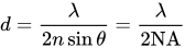
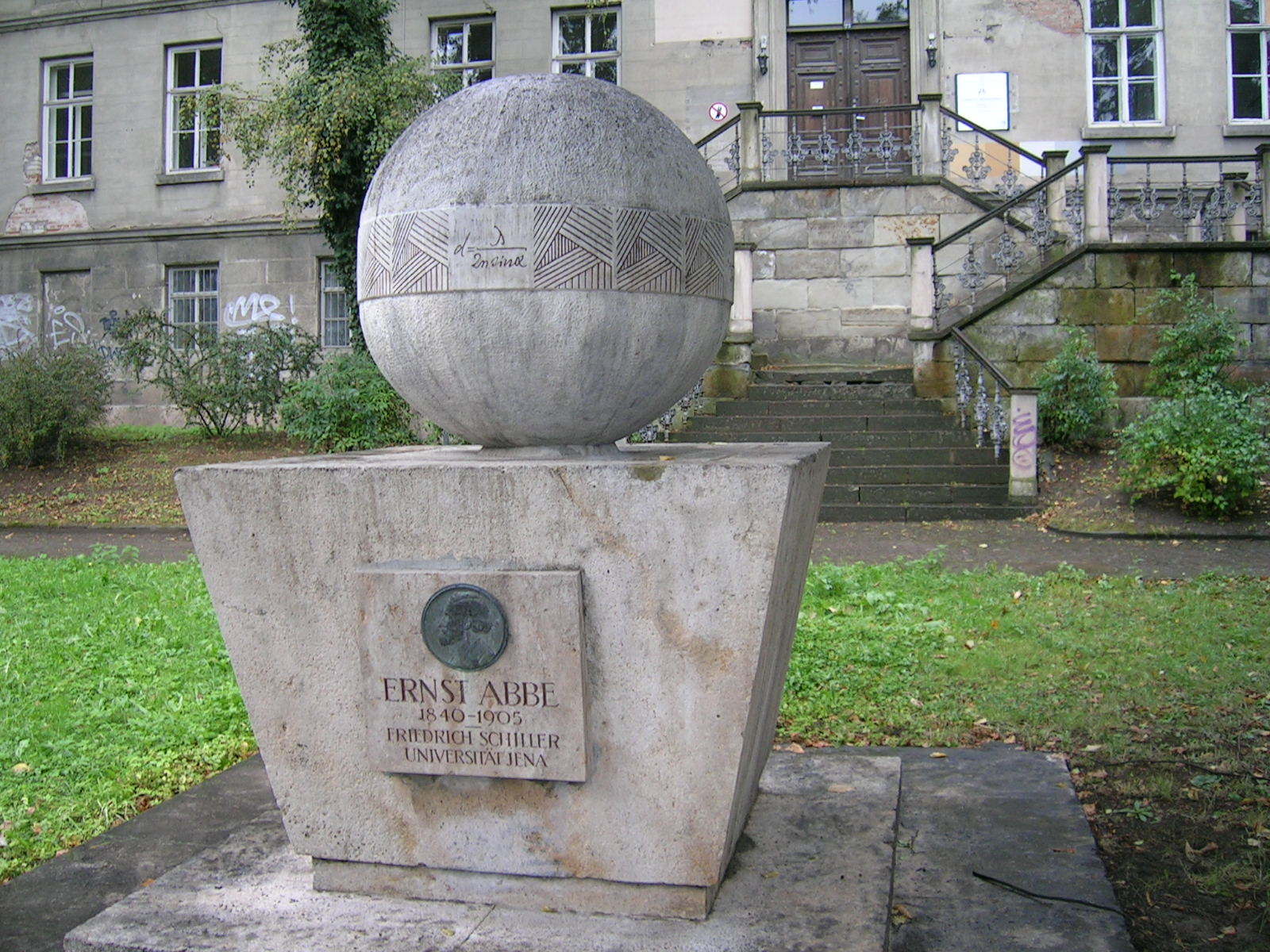
Memorial in Jena, Germany to Ernst Karl Abbe, who approximated the diffraction limit of a microscope as , where d is the resolvable feature size, λ is the wavelength of light, n is the index of refraction of the medium being imaged in, and θ (depicted as α in the inscription) is the half-angle subtended by the optical objective lens (representing the numerical aperture).
Log-log plot of aperture diameter vs angular resolution at the diffraction limit for various light wavelengths compared with various astronomical instruments. For example, the blue star shows that the Hubble Space Telescope is almost diffraction-limited in the visible spectrum at 0.1 arcsecs, whereas the red circle shows that the human eye should have a resolving power of 20 arcsecs in theory, though normally only 60 arcsecs.

In optics, any optical instrument or system – a microscope, telescope, or camera – has a principal limit to its resolution due to the physics of diffraction. An optical instrument is said to be diffraction-limited if it has reached this limit of resolution performance. Other factors may affect an optical system's performance, such as lens imperfections or aberrations, but these are caused by errors in the manufacture or calculation of a lens, whereas the diffraction limit is the maximum resolution possible for a theoretically perfect, or ideal, optical system.[1]

The diffraction-limited angular resolution, in radians, of an instrument is proportional to the wavelength of the light being observed, and inversely proportional to the diameter of its objective's entrance aperture. For telescopes with circular apertures, the size of the smallest feature in an image that is diffraction limited is the size of the Airy disk. As one decreases the size of the aperture of a telescopic lens, diffraction proportionately increases. At small apertures, such as f/22, most modern lenses are limited only by diffraction and not by aberrations or other imperfections in the construction.

For microscopic instruments, the diffraction-limited spatial resolution is proportional to the light wavelength, and to the numerical aperture of either the objective or the object illumination source, whichever is smaller.

In astronomy, a diffraction-limited observation is one that achieves the resolution of a theoretically ideal objective in the size of instrument used. However, most observations from Earth are seeing-limited due to atmospheric effects. Optical telescopes on the Earth work at a much lower resolution than the diffraction limit because of the distortion introduced by the passage of light through several kilometres of turbulent atmosphere. Advanced observatories have started using adaptive optics technology, resulting in greater image resolution for faint targets, but it is still difficult to reach the diffraction limit using adaptive optics.

Radio telescopes are frequently diffraction-limited, because the wavelengths they use (from millimeters to meters) are so long that the atmospheric distortion is negligible. Space-based telescopes (such as Hubble, or a number of non-optical telescopes) always work at their diffraction limit, if their design is free of optical aberration.

The beam from a laser with near-ideal beam propagation properties may be described as being diffraction-limited. A diffraction-limited laser beam, passed through diffraction-limited optics, will remain diffraction-limited, and will have a spatial or angular extent essentially equal to the resolution of the optics at the wavelength of the laser.

Calculation of diffraction limit

[edit]

The Abbe diffraction limit for a microscope

[edit]

The observation of sub-wavelength structures with microscopes is difficult because of the Abbe diffraction limit. Ernst Abbe first mentioned the diffraction limit in his 1873 paper, page 466: „[…] die physikalische Unterscheidungsgrenze […] hängt allein vom Oeffnungswinkel ab und ist dem Sinus seines halben Betrages proportional“, or "[…] the physical limit of resolution […] depends solely on the aperture angle and is proportional to the sine of half its magnitude".[2] Abbe wrote it in form of a formula in his 1882 paper, page 461: "The smallest dimensions which are within the reach of a given aperture are indicated with sufficient accuracy by taking the limit of the resolving or separating power of that aperture for periodic or regular structures, i.e. the minimum distance apart at which given elements can be delineated separately with the aperture in question. The numerical expression of that minimum distance is" [3]

,

where is the wavelength, is the refractive index of the medium, and is the semi-angle of the light focused by the optical system. The same formula had been proven by Hermann von Helmholtz in 1874.[4] The portion of the denominator is called the numerical aperture (NA) and can reach about 1.4–1.6 in modern optics, hence the Abbe limit is .

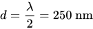
Considering green light around 500 nm and a NA of 1, the Abbe limit is roughly (0.25 μm), which is small compared to most biological cells (1 μm to 100 μm), but large compared to viruses (100 nm), proteins (10 nm) and less complex molecules (1 nm). To increase the resolution, shorter wavelengths can be used such as UV and X-ray microscopes. These techniques offer better resolution but are expensive, suffer from lack of contrast in biological samples and may damage the sample.
Digital photography

[edit]

In a digital camera, diffraction effects interact with the effects of the regular pixel grid. The combined effect of the different parts of an optical system is determined by the convolution of the point spread functions (PSF). The point spread function of a diffraction limited circular-aperture lens is simply the Airy disk. The point spread function of the camera, otherwise called the instrument response function (IRF) can be approximated by a rectangle function, with a width equivalent to the pixel pitch. A more complete derivation of the modulation transfer function (derived from the PSF) of image sensors is given by Fliegel.[5] Whatever the exact instrument response function, it is largely independent of the f-number of the lens. Thus at different f-numbers a camera may operate in three different regimes, as follows:

  1. In the case where the spread of the IRF is small with respect to the spread of the diffraction PSF, in which case the system may be said to be essentially diffraction limited (so long as the lens itself is diffraction limited).
  2. In the case where the spread of the diffraction PSF is small with respect to the IRF, in which case the system is instrument limited.
  3. In the case where the spread of the PSF and IRF are similar, in which case both impact the available resolution of the system.

The spread of the diffraction-limited PSF is approximated by the diameter of the first null of the Airy disk,

[6]

where is the wavelength of the light and is the f-number of the imaging optics, i.e., in the Abbe diffraction limit formula. For instance, for an f/8 lens ( and ) and for green light ( 0.5 μm wavelength) light, the focusing spot diameter will be d = 9.76 μm or 19.5. This is similar to the pixel size for the majority of commercially available 'full frame' (43mm sensor diagonal) cameras and so these will operate in regime 3 for f-numbers around 8 (few lenses are close to diffraction limited at f-numbers smaller than 8).

Cameras with smaller sensors will tend to have smaller pixels, but their lenses will be designed for use at smaller f-numbers and it is likely that they will also operate in regime 3 for those f-numbers for which their lenses are diffraction limited. Given the same field of view, pixel count, shutter speed and shot noise SNR (i.e. the same amount of light collected per pixel), a small sensor and a large sensor of equivalent quality will produce the same digital image, with the same amount of blur due to both diffraction and depth of field.[7] The larger sensors do have an advantage in that the lenses for them tend to have larger maximum entrance pupils, which allows, to a larger extent, trading depth of field for less diffraction blur and either more SNR or higher shutter speeds.[8]

Obtaining higher resolution

[edit]

Using special optical systems and digital image processing, it is possible to produce images that have higher resolution (in some specific aspects of the subject, such as color or shape) than would be allowed by simple use of diffraction-limited optics.[9] These largely computational methods offer advantages over other workarounds such as electron microscopy, and have been used to produce reasonably accurate images of individual molecules.[10][11] Although these techniques improve some aspect of resolution, they generally come at an enormous increase in cost and complexity compared to using a simple light microscope. Usually the technique is only appropriate for a small subset of imaging problems, with several general approaches outlined below.

Extending numerical aperture

[edit]

The effective resolution of a microscope can be improved by illuminating from the side.

In conventional microscopes such as bright-field or differential interference contrast, this is achieved by using a condenser. Under spatially incoherent conditions, the image is understood as a composite of images illuminated from each point on the condenser, each of which covers a different portion of the object's spatial frequencies.[12] This effectively improves the resolution by, at most, a factor of two.

Simultaneously illuminating from all angles (fully open condenser) drives down interferometric contrast. In conventional microscopes, the maximum resolution (fully open condenser, at N = 1) is rarely used. Further, under partially coherent conditions, the recorded image is often non-linear with object's scattering potential—especially when looking at non-self-luminous (non-fluorescent) objects.[13] To boost contrast, and sometimes to linearize the system, unconventional microscopes (with structured illumination) synthesize the condenser illumination by acquiring a sequence of images with known illumination parameters. Typically, these images are composited to form a single image with data covering a larger portion of the object's spatial frequencies when compared to using a fully closed condenser (which is also rarely used).

Another technique, 4Pi microscopy, uses two opposing objectives to double the effective numerical aperture, effectively halving the diffraction limit, by collecting the forward and backward scattered light. When imaging a transparent sample, with a combination of incoherent or structured illumination, as well as collecting both forward, and backward scattered light it is possible to image the complete scattering sphere.

Unlike methods relying on localization, such systems are still limited by the diffraction limit of the illumination (condenser) and collection optics (objective), although in practice they can provide substantial resolution improvements compared to conventional methods.

Near-field techniques

[edit]

The diffraction limit is only valid in the far field as it assumes that no evanescent fields reach the detector. Various near-field techniques that operate less than ≈1 wavelength of light away from the image plane can obtain substantially higher resolution. These techniques exploit the fact that the evanescent field contains information beyond the diffraction limit which can be used to construct very high resolution images, in principle beating the diffraction limit by a factor proportional to how well a specific imaging system can detect the near-field signal. For scattered light imaging, instruments such as near-field scanning optical microscopes and nano-FTIR, which are built atop atomic force microscope systems, can be used to achieve up to 10-50 nm resolution. The data recorded by such instruments often requires substantial processing, essentially solving an optical inverse problem for each image.

Metamaterial-based superlenses can image with a resolution better than the diffraction limit by locating the objective lens extremely close (typically hundreds of nanometers) to the object.

In fluorescence microscopy the excitation and emission are typically on different wavelengths. In total internal reflection fluorescence microscopy a thin portion of the sample located immediately on the cover glass is excited with an evanescent field, and recorded with a conventional diffraction-limited objective, improving the axial resolution.

However, because these techniques cannot image beyond 1 wavelength, they cannot be used to image into objects thicker than 1 wavelength which limits their applicability.

Far-field techniques

[edit]

Far-field imaging techniques are most desirable for imaging objects that are large compared to the illumination wavelength but that contain fine structure. This includes nearly all biological applications in which cells span multiple wavelengths but contain structure down to molecular scales. In recent years several techniques have shown that sub-diffraction limited imaging is possible over macroscopic distances. These techniques usually exploit optical nonlinearity in a material's reflected light to generate resolution beyond the diffraction limit.

Among these techniques, the STED microscope has been one of the most successful. In STED, multiple laser beams are used to first excite, and then quench fluorescent dyes. The nonlinear response to illumination caused by the quenching process in which adding more light causes the image to become less bright generates sub-diffraction limited information about the location of dye molecules, allowing resolution far beyond the diffraction limit provided high illumination intensities are used.

Laser beams

[edit]

The limits on focusing or collimating a laser beam are very similar to the limits on imaging with a microscope or telescope. The only difference is that laser beams are typically soft-edged beams. This non-uniformity in light distribution leads to a coefficient slightly different from the 1.22 value familiar in imaging. However, the scaling with wavelength and aperture is exactly the same.

The beam quality of a laser beam is characterized by how well its propagation matches an ideal Gaussian beam at the same wavelength. The beam quality factor M squared (M2) is found by measuring the size of the beam at its waist, and its divergence far from the waist, and taking the product of the two, known as the beam parameter product. The ratio of this measured beam parameter product to that of the ideal is defined as M2, so that M2=1 describes an ideal beam. The M2 value of a beam is conserved when it is transformed by diffraction-limited optics.

The outputs of many low and moderately powered lasers have M2 values of 1.2 or less, and are essentially diffraction-limited.

The M2 factor enters various equations, correcting for the non-ideality of the beam. For example, the smallest possible spot size obtainable by focusing a parallel laser beam by a lens is

,

where is the focal length of the lens and is the beam diameter.[14]

Other waves

[edit]

The same principle applies to other wave-based sensors, such as radar and the human ear. It can also be generalized to massive particles with the de Broglie wavelength, inversely proportional to the particle momentum, serving as an effective wavelength. For example, an electron at an energy of 10 keV has a wavelength of about 0.01 nm, allowing the electron microscope (SEM or TEM) to achieve high resolution images.

See also

[edit]

References

[edit]
[edit]
Revisions and contributorsEdit on WikipediaRead on Wikipedia
from Grokipedia
A diffraction-limited system is an ideal optical instrument, such as a microscope, telescope, or camera, in which the resolution and image quality are constrained solely by the wave nature of light—specifically, diffraction effects at the system's aperture—rather than by imperfections like lens aberrations, manufacturing errors, or atmospheric turbulence.[1][2] In such systems, light waves passing through a finite aperture spread out, forming a diffraction pattern that sets the fundamental limit on the smallest resolvable detail, typically quantified by the Airy disk, the central bright spot surrounded by concentric rings.[3] This limit arises from the Huygens-Fresnel principle, where every point on a wavefront acts as a source of secondary spherical wavelets, leading to interference that blurs point sources into finite-sized images.[4] The resolution of a diffraction-limited system is most commonly assessed using the Rayleigh criterion, which defines the minimum angular separation θ between two point sources as just resolvable when the central maximum of one Airy disk falls on the first minimum of the other, given by θ ≈ 1.22 λ / D for a circular aperture, where λ is the wavelength of light and D is the aperture diameter.[3][5] This yields a linear spot size in the image plane of approximately D₀ ≈ 2.44 λ (f/#), with f/# denoting the f-number (focal length divided by aperture diameter), highlighting how shorter wavelengths and larger apertures improve performance.[2] For multi-element systems, the effective resolution adjusts to D₀ ≈ 2.44 λ f_eff / d_NP, where f_eff is the effective focal length and d_NP the entrance pupil diameter.[2] In practice, diffraction-limited performance represents the theoretical benchmark for optical design, achievable under ideal conditions with aberration-free optics and coherent or incoherent illumination.[1] The system's point spread function (PSF), which describes the response to a point source, is the Airy pattern for circular apertures in the Fraunhofer (far-field) approximation, acting as a low-pass spatial filter that attenuates high-frequency details beyond the cutoff frequency proportional to D / (λ f).[2] Applications span astronomy, where space-based telescopes like Hubble operate near this limit to resolve distant stars, to microscopy, where it constrains the Abbe diffraction limit (d ≈ λ / (2 NA), with NA the numerical aperture).[4] However, real-world factors like partial coherence or environmental disturbances can degrade performance, prompting techniques such as adaptive optics to approach the limit more closely.[2]

Fundamentals

Definition and Principles

A diffraction-limited system refers to an ideal optical instrument, such as a lens or telescope, in which the smallest resolvable feature size is determined exclusively by the diffraction effects of light waves, rather than by imperfections like lens aberrations, scattering, or manufacturing errors.[6] In such systems, the performance achieves the theoretical maximum resolution allowed by the physics of wave propagation, distinguishing them from aberration-limited systems where optical flaws degrade the image quality beyond the diffraction constraint.[7] The fundamental physical basis for this limitation arises from the wave nature of light, which causes wavefronts passing through an aperture to interfere and produce diffraction patterns that spread out the image of a point source into a finite area rather than a perfect point.[8] This diffraction is governed by the Huygens-Fresnel principle, which states that every point on an advancing wavefront serves as a source of secondary spherical wavelets, and the new wavefront is the envelope of these wavelets with their amplitudes combining through interference to form the observed pattern.[9] For example, in a perfect lens focusing a point source, the resulting image manifests as a blurred diffraction pattern due to this wave interference, setting an inherent bound on sharpness.[10] The term "diffraction-limited" emerged in the late 19th century through studies of telescope optics, notably in Lord Rayleigh's 1879 paper, where he examined how diffraction imposes a resolution limit on spectroscopic instruments and stellar imaging by analyzing the interference from circular apertures.[11] This work built on earlier wave optics foundations, emphasizing that resolution in such systems depends primarily on the light's wavelength λ and the aperture diameter, as shorter wavelengths and larger apertures minimize the angular extent of diffraction.[12] These principles underpin the understanding of resolution in all wave-based imaging, from visible light to other electromagnetic spectra.[13]

Rayleigh Criterion

The Rayleigh criterion establishes the threshold for resolving two closely spaced point sources in a diffraction-limited optical system, specifying that they are just resolvable when the central maximum of the Airy diffraction pattern from one source coincides with the first minimum of the pattern from the other.[14] This condition ensures a detectable dip in the combined intensity profile between the two sources, marking the practical limit of angular resolution.[14] For a circular aperture of diameter DD, the minimum resolvable angular separation θ\theta is given by
θ=1.22λD, \theta = 1.22 \frac{\lambda}{D},
where λ\lambda is the wavelength of the light; this formula applies under small-angle approximations where sinθθ\sin \theta \approx \theta.[15] The derivation stems from the Fraunhofer diffraction pattern for a circular aperture, where the intensity distribution is
I(θ)[2J1(kasinθ)kasinθ]2. I(\theta) \propto \left[ \frac{2 J_1 (k a \sin \theta)}{k a \sin \theta} \right]^2.
Here, J1J_1 denotes the first-order Bessel function of the first kind, k=2π/λk = 2\pi / \lambda is the wavenumber, and a=D/2a = D/2 is the aperture radius; the first minimum occurs at kasinθ3.8317k a \sin \theta \approx 3.8317, yielding the factor 1.22 since 3.8317/π1.223.8317 / \pi \approx 1.22.[15] This criterion underpins the design of astronomical telescopes, where increasing the aperture diameter DD directly enhances angular resolution, enabling the distinction of finer details in distant celestial objects such as binary stars.[16] However, it assumes incoherent illumination between the point sources and monochromatic light, rendering it inapplicable to coherent sources or broadband illumination; additionally, it pertains specifically to point-like objects and does not extend to the resolution of extended structures.[17]

Resolution Calculations

Abbe Diffraction Limit

The Abbe diffraction limit, formulated by German physicist Ernst Abbe in 1873, established the theoretical foundation for the resolution capabilities of optical microscopes by incorporating the wave nature of light and diffraction effects. This work, detailed in his seminal publication, resolved contemporary debates on the intrinsic limits of microscopic imaging, shifting the focus from purely geometrical optics to a diffraction-based understanding that emphasized the role of the objective lens in capturing scattered light from the specimen. Abbe's theory demonstrated that microscope performance is constrained by the inability to collect all diffracted orders from fine structures, thereby setting a physical boundary independent of lens quality or magnification. The limit defines the smallest resolvable distance $ d $ in the object plane as $ d = \frac{\lambda}{2 \mathrm{NA}} $, where $ \lambda $ is the illumination wavelength and $ \mathrm{NA} $ is the numerical aperture of the objective, given by $ \mathrm{NA} = n \sin \alpha $ with $ n $ as the refractive index of the imaging medium and $ \alpha $ as the half-angle subtended by the objective at the focal point. Abbe derived this through analysis of light diffraction by a periodic grating in the specimen plane, analogous to resolving closely spaced lines. The grating produces diffraction orders at angles $ \theta_m = m \lambda / d $ for integer order $ m ,andtheobjectivecollectstheseuptothemaximumangledeterminedbyNA;thezerothandfirstorders(, and the objective collects these up to the maximum angle determined by NA; the zeroth and first orders ( m = 0, \pm 1 $) must be captured to reconstruct the fundamental periodicity, leading to the minimal $ d $ when the first-order angle equals $ \alpha $. This ties resolution to the highest transmissible spatial frequency $ k_{\max} = \frac{2\pi \mathrm{NA}}{\lambda} $, beyond which higher frequencies (finer details) are evanescent or uncollected, filtering out sub-resolution information in the Fourier domain of the image. For incoherent illumination, common in standard microscopy, the formula $ d = \frac{\lambda}{2 \mathrm{NA}} $ holds, as intensity patterns allow the optical transfer function to extend to $ 2 \mathrm{NA}/\lambda $ in spatial frequency, doubling the coherent cutoff. In contrast, coherent illumination restricts the transferable frequencies to $ \mathrm{NA}/\lambda $, yielding a poorer resolution of $ d = \frac{\lambda}{\mathrm{NA}} $, since phase relationships limit the effective bandwidth. These distinctions arise from the differing modulation transfer functions: incoherent light integrates over independent wavefronts, enhancing contrast for high frequencies, while coherent light suffers from coherent artifacts. The Abbe limit imposes a fundamental constraint on conventional light microscopy, typically limiting lateral resolution to approximately 200 nm for visible wavelengths ($ \lambda \approx 500 $ nm) and high-NA objectives (NA ≈ 1.4), far exceeding the size of many cellular structures like proteins or vesicles. This bound underscores the necessity of shorter wavelengths or specialized techniques to probe nanoscale biology, as it prevents faithful imaging of features smaller than half the wavelength without evoking diffraction blurring.

Airy Disk Formulation

The Airy disk is the central bright spot in the far-field diffraction pattern formed by a point source of light passing through a circular aperture, surrounded by alternating concentric rings of decreasing intensity. This pattern arises due to wave interference in the Fraunhofer diffraction regime, where the aperture acts as a spatial filter that spreads the otherwise point-like image into a diffuse distribution.[18] The mathematical formulation of the Airy disk was first derived by George Biddell Airy in his 1835 analysis of diffraction through a circular object-glass. The derivation involves evaluating the Fraunhofer diffraction integral for a uniform circular aperture of diameter DD, yielding the amplitude as the Fourier transform of the circular pupil function, which results in a sombrero-shaped function involving the first-order Bessel function.[19][15] The radius rr of the first dark ring, marking the boundary of the central Airy disk in the focal plane of a lens with focal length ff, is given by
r=1.22λfD, r = 1.22 \frac{\lambda f}{D},
where λ\lambda is the wavelength of light. This linear radius corresponds to an angular radius θ\theta from the optical axis of
θ=1.22λD. \theta = 1.22 \frac{\lambda}{D}.
These expressions highlight the inverse dependence on aperture size, illustrating how larger apertures reduce the diffraction blur.[18][7] The intensity profile I(θ)I(\theta) of the Airy pattern, normalized to the central maximum I0I_0, is described by \begin{equation} I(\theta) = I_0 \left[ \frac{2 J_1(x)}{x} \right]^2, \end{equation} where J1J_1 is the first-order Bessel function of the first kind, and the argument xx is
x=πDsinθλ. x = \frac{\pi D \sin \theta}{\lambda}.
For small angles, sinθθ\sin \theta \approx \theta, simplifying the profile. The first minimum occurs at x3.8317x \approx 3.8317, corresponding to the factor of 1.22 in the radius formulas. This intensity distribution is obtained by squaring the modulus of the diffracted field amplitude from the circular aperture integral.[15][7] The Airy disk pattern serves as the point spread function (PSF) in ideal diffraction-limited optical systems, representing the response to a point object and thus quantifying the inherent blur in image formation. Approximately 84% of the total diffracted energy is concentrated within the central disk, with the remainder distributed in the surrounding rings.[20] For non-circular apertures, such as rectangular ones, the diffraction pattern deviates from the Airy form; the intensity follows a sinc2\operatorname{sinc}^2 profile in each dimension instead of the squared Bessel function, resulting in a cross-shaped pattern with slightly broader effective width and altered resolution properties compared to the circular case.[18]

Imaging Applications

Microscopy

In light microscopy, the diffraction limit fundamentally constrains the achievable resolution, typically around 200-300 nm for visible light wavelengths, as the finite size of the objective lens aperture blurs fine details beyond this scale. This limit arises from the wave nature of light, where the smallest resolvable feature is governed by the wavelength and the numerical aperture (NA) of the system, preventing the clear distinction of sub-wavelength structures in biological specimens or materials. For instance, in standard bright-field microscopy, which relies on transmitted light to image unstained samples, the diffraction limit restricts visualization of cellular organelles or nanostructures to this range, making it challenging to resolve features like individual protein complexes without additional techniques. Oil immersion objectives enhance resolution by increasing the NA to approximately 1.4 through the use of high-refractive-index immersion media, which minimizes light refraction at the sample-lens interface and effectively reduces the diffraction-limited spot size to about 150 nm. This improvement is particularly valuable in fluorescence microscopy, where fluorophores label specific biomolecules, allowing targeted imaging of cellular components such as microtubules or synaptic vesicles; however, even here, the diffraction limit confines the precision of localization to roughly half the excitation wavelength. Confocal microscopy, a precursor to super-resolution methods, mitigates some diffraction effects by using a pinhole to reject out-of-focus light, effectively increasing the NA and improving axial resolution to around 500-700 nm, though lateral resolution remains near the conventional limit. Historically, the Abbe diffraction limit, which defines the minimal resolvable distance as λ/(2NA), limited the visualization of viruses and other sub-200 nm pathogens in light microscopy, necessitating the development of electron microscopy for their study in the mid-20th century. In practice, imaging cells or nanostructures—such as lipid bilayers in neuronal membranes—often exemplifies these constraints, where diffraction blurring can obscure critical details like vesicle fusion events unless samples are optimized. Challenges in achieving the theoretical limit include refractive index mismatches between the sample, mounting medium, and objective, which can degrade resolution by up to 20-30% due to spherical aberrations, particularly in thick biological tissues. Advancements in microscopy have pushed beyond these limits through super-resolution techniques, such as structured illumination microscopy (SIM), which uses patterned illumination to reconstruct sub-diffraction details down to 100 nm by exploiting higher spatial frequencies in the diffraction pattern. These methods, including STED and PALM, build on the foundational diffraction constraints of conventional systems but are explored in greater depth elsewhere. Recent progress as of the 2020s incorporates adaptive optics to correct for sample-induced aberrations in live-cell imaging, enabling diffraction-limited performance in dynamic biological processes like embryonic development.

Telescopes and Astronomy

In astronomical telescopes, the diffraction limit sets the fundamental angular resolution for observing distant celestial objects, determined by the ratio of the observation wavelength to the telescope's aperture diameter, approximated as θλ/D\theta \approx \lambda / D, where θ\theta is in radians. This limit arises from the wave nature of light, causing point sources to spread into Airy disks rather than perfect points, as first mathematically described by George Biddell Airy in 1835 for the diffraction pattern and refined by Lord Rayleigh in the late 19th century to define the minimum resolvable angular separation. For ground-based telescopes, atmospheric turbulence—known as "seeing"—typically dominates, blurring images to 0.5–2 arcseconds, far exceeding the diffraction limit of even large apertures. However, space-based observatories avoid this, achieving near-theoretical performance. The Hubble Space Telescope, with its 2.4-meter mirror, exemplifies diffraction-limited performance in visible light, reaching an angular resolution of approximately 0.05 arcseconds at 500 nm wavelength, enabling detailed imaging of galaxies and nebulae otherwise blurred by Earth's atmosphere. Similarly, the James Webb Space Telescope (JWST), launched in December 2021 with a 6.5-meter primary mirror, operates diffraction-limited in the near-infrared, providing resolutions around 0.1 arcseconds at wavelengths near 2 micrometers, which has revolutionized observations of early universe structures and exoplanet atmospheres. For ground-based 8-meter-class telescopes like those at the Very Large Telescope array, the diffraction limit in the infrared (e.g., at ~0.8 micrometers) is about 0.02 arcseconds, though seeing often limits practical resolution to coarser scales; adaptive optics systems correct for atmospheric distortions in real-time using deformable mirrors and laser guide stars, approaching but not surpassing the inherent diffraction limit. This diffraction constraint profoundly impacts exoplanet detection, as the angular separation between a star and its planet is typically smaller than the resolution for apertures under tens of meters, contaminating planetary signals with stellar glare and hindering direct imaging. Astronomical interferometry addresses this by combining light from multiple telescopes to simulate a much larger effective aperture, extending resolution beyond single-telescope diffraction limits—for instance, the Very Large Telescope Interferometer achieves baselines equivalent to hundreds of meters for sub-milliarcsecond precision in infrared. In radio astronomy, where wavelengths span centimeters to meters, the diffraction limit necessitates enormous diameters (up to 500 meters, as in China's Five-hundred-meter Aperture Spherical Telescope (FAST))[21] to achieve comparable angular resolutions to optical telescopes, since longer λ\lambda requires proportionally larger DD to maintain small θ\theta; arrays like the Atacama Large Millimeter/submillimeter Array use interferometry to further enhance this effective scale.

Digital Photography

In digital photography, diffraction becomes a significant constraint when using small apertures, corresponding to high f-numbers, as the resulting Airy disk expands to exceed the size of individual pixels on the sensor, leading to overall image softening and reduced sharpness.[7] For green light at approximately 550 nm wavelength, the Airy disk diameter is about 10.15 µm at f/8, which can begin to blur fine details on full-frame sensors where pixel pitches typically range from 4 to 6 µm depending on resolution.[7] This effect is particularly noticeable in landscapes or macro shots requiring deep depth of field, where photographers often stop down to f/8 or f/11, marking a practical limit for many full-frame digital single-lens reflex (DSLR) and mirrorless cameras to balance sharpness and focus range.[22] The interaction between diffraction and pixel sampling follows the Nyquist criterion, which requires that the pixel pitch be at most half the smallest resolvable feature to avoid aliasing; in practice, effective resolution drops when the Airy disk diameter exceeds roughly twice the pixel pitch, as the sensor cannot adequately sample the blurred point spread function.[23] For a 20 MP full-frame sensor with a pixel pitch of about 6.6 µm, diffraction-induced softening becomes prominent beyond f/16, while higher-resolution sensors like the 50 MP Sony A1 (pixel pitch ~4.1 µm) encounter limits as early as f/5.6, where the Airy disk spans multiple pixels and erodes contrast.[22] Smartphones, with their much smaller sensors and pixel pitches often below 1 µm, reach diffraction limits even at wide apertures like f/2.8, in contrast to DSLRs where larger pixels delay visible softening until higher f-numbers; this makes diffraction more critical for high-megapixel consumer cameras in print or crop-heavy workflows than for lower-resolution devices.[22][24] Mitigation strategies in digital photography include computational post-processing techniques, such as diffraction correction algorithms that model and reverse the blurring effect based on lens profiles and aperture settings.[25] Canon's Digital Photo Professional software, for instance, uses the Digital Lens Optimizer to apply targeted corrections for diffraction alongside other aberrations, restoring some lost resolution without altering the original raw data.[25] For sub-diffraction-limit pixels common in modern high-resolution sensors, oversampling during capture can reduce aliasing, though it trades off signal-to-noise ratio; overall, diffraction remains negligible for low-resolution sensors or web viewing but essential to consider for large prints or detailed landscapes where maximum acuity is prioritized.[24][22]

Overcoming Diffraction Limits

Increasing Numerical Aperture

Increasing the numerical aperture (NA) of an optical system is a fundamental approach to enhancing resolution in diffraction-limited imaging by capturing a greater portion of the diffracted light from the specimen. The NA, defined as $ n \sin \theta $, where $ n $ is the refractive index of the medium between the objective and the specimen, and $ \theta $ is the half-angle of the maximum cone of light accepted by the objective, determines the number of diffraction orders that can be collected. By employing immersion fluids with higher refractive indices than air ($ n = 1 ),suchas[water](/page/Water)(), such as [water](/page/Water) ( n \approx 1.33 )or[oil](/page/Oil!)() or [oil](/page/Oil!) ( n \approx 1.52 $), the NA can exceed 1.4, allowing the system to gather more high-angle diffracted rays and thereby improve the lateral resolution beyond the Abbe diffraction limit of approximately $ \lambda / (2 \mathrm{NA}) $, where $ \lambda $ is the wavelength.[26][27][28] Advanced objective lens designs incorporate aspheric elements to maintain high NA while minimizing off-axis aberrations, enabling compact systems with NAs up to 1.4 in oil immersion. Solid immersion lenses (SILs), typically hemispherical or super-hemispherical microlenses made from high-index materials like silicon ($ n \approx 3.5 $) or gallium phosphide, further elevate the effective NA to values exceeding 3 in near-field configurations by reducing the focal length and increasing the angular acceptance without introducing significant spherical aberration when properly aplanatic. These techniques were pioneered in the late 19th century by Ernst Abbe, who developed the first immersion objectives using fluids like cinnamic aldehyde in 1876, laying the groundwork for apochromatic designs that corrected chromatic aberrations in high-NA systems. In specialized setups like 4Pi microscopy, two opposing high-NA objectives (typically NA = 1.4) are used to illuminate and detect from opposite sides, effectively doubling the axial NA and achieving resolutions down to 100 nm.[29][30][31][32] However, higher NA introduces challenges, particularly increased spherical and chromatic aberrations due to refractive index mismatches, especially when imaging deeper into specimens, necessitating corrective elements like deformable mirrors or adaptive optics for compensation. Recent research since 2020 has explored metamaterials, such as hyperbolic designs, to achieve hyper-NA values beyond traditional limits by engineering subwavelength structures that manipulate light propagation, though practical implementations remain limited by fabrication complexities and losses. Overall, these NA enhancements proportionally scale resolution with the NA ratio—for instance, doubling NA halves the minimum resolvable feature size—but the system remains fundamentally constrained by the diffraction limit.[33][34][35][36]

Near-Field Techniques

Near-field techniques in optics, exemplified by scanning near-field optical microscopy (SNOM), circumvent the diffraction limit by exploiting evanescent waves that arise from sub-wavelength interactions between a probe and the sample. These non-propagating waves, which carry high spatial frequency information about nanoscale structures, decay exponentially with distance, typically over distances shorter than half the illumination wavelength (λ/2). By positioning the probe within 10-50 nm of the sample surface, SNOM captures these evanescent fields, enabling optical resolutions of 10-100 nm, far surpassing the far-field limit of approximately λ/2.[37][38] The foundational principles of SNOM emerged in the 1980s, building on the theoretical concept proposed by E.H. Synge in 1928 and the first scanning near-field experiment by Ash and Nichols in 1972 (in the microwave regime), achieving practical implementation through scanning probe innovations. Pioneering experiments by Dieter Pohl and colleagues at IBM in 1984 demonstrated optical imaging with resolutions approaching λ/20 using a sub-wavelength aperture, marking the birth of aperture-based SNOM. Eric Betzig's subsequent work in the early 1990s further advanced the technique, integrating it with fluorescence detection for biological applications and contributing to the broader evolution of super-resolution methods, which earned him a share of the 2014 Nobel Prize in Chemistry for fluorescence-based breakthroughs, though SNOM itself predates and complements those far-field approaches.[39][40] SNOM operates in two primary configurations: aperture and apertureless modes. In aperture SNOM, light is confined through a metal-coated tapered optical fiber ending in a nanoscale aperture (typically 50-100 nm in diameter), which illuminates or collects evanescent fields as the probe raster-scans the sample. This method achieves resolutions of 50-150 nm, limited by aperture size and light throughput, but provides direct optical contrast without background interference. Apertureless SNOM, developed in the late 1980s and refined in the 1990s, employs a sharp non-apertured probe, such as an atomic force microscopy (AFM) tip, to scatter incident light and enhance local fields via antenna-like effects; resolutions reach 5-30 nm, offering higher spatial detail but requiring demodulation to suppress far-field contributions.[37][41][42] These techniques have proven valuable for imaging biomolecules, where they reveal sub-diffraction details in complex assemblies. For instance, aperture SNOM has imaged single fluorescent dye molecules and protein distributions on cell membranes with ~20 nm resolution, enabling studies of molecular interactions without invasive labeling. Apertureless variants have visualized virus particles, amyloid fibrils, and silk protein nanostructures, combining topographic and optical data to map biomolecular orientation and aggregation at the nanoscale.[43][44][45] SNOM's key advantages include true nanoscale optical imaging with spectroscopic capabilities, allowing chemical identification alongside morphology, which is ideal for non-destructive analysis of delicate samples like biomolecules. However, limitations persist: mechanical scanning results in slow acquisition times (often minutes to hours for high-resolution images), and intense local fields can cause photobleaching or thermal damage, particularly in apertureless mode where laser powers are higher.[46][47][48] In the 2020s, plasmonic enhancements have addressed throughput challenges by integrating metallic nanostructures into probes, amplifying evanescent fields and enabling faster, higher-sensitivity imaging. Plasmon-coupled tips, for example, boost signal collection by orders of magnitude, facilitating ultrafast nano-spectroscopy of dynamic biological processes with sub-10 nm resolution.[49][50]

Far-Field Super-Resolution Methods

Far-field super-resolution methods enable imaging beyond the classical diffraction limit by manipulating the illumination or detection process to encode and retrieve higher spatial frequencies from the sample, while operating entirely within the propagating far-field regime. These techniques effectively increase the numerical aperture (NA) through optical or computational means, achieving resolutions on the order of λ/(2 NA_eff), where NA_eff exceeds the physical NA of the system. Unlike hardware-limited approaches, they rely on nonlinear interactions or precise localization to bypass the Abbe limit without requiring proximity to the sample. Structured illumination microscopy (SIM) is a foundational far-field technique that illuminates the sample with patterned light, such as sinusoidal fringes, to shift higher-frequency information into the detectable passband of the microscope. By acquiring multiple images under shifted illumination patterns and computationally reconstructing the data, SIM can double the resolution in all dimensions, typically achieving ~100-150 nm laterally for visible light. This method was pioneered in the early 2000s and has become widely adopted for its compatibility with standard fluorescence setups. Stimulated emission depletion (STED) microscopy achieves super-resolution by using a doughnut-shaped depletion beam to inhibit fluorescence from molecules in the periphery of the excitation spot, confining emission to a sub-diffraction central region. The resolution scales inversely with the square root of the depletion intensity, enabling lateral resolutions as fine as 20-50 nm, depending on laser power and molecular photostability. Developed by Stefan Hell in the late 1990s, STED represents a deterministic approach that avoids stochastic switching, making it suitable for video-rate imaging in live cells. Photoactivated localization microscopy (PALM) and stochastic optical reconstruction microscopy (STORM) rely on the precise localization of individual fluorophores that are stochastically activated and imaged in sparse subsets over multiple cycles. By fitting the point spread function to these blinking events, positions can be determined with ~10-20 nm precision, yielding reconstructed images with resolutions approaching 20 nm after accumulating thousands of frames. These methods, introduced around 2006, revolutionized single-molecule tracking and have been essential for visualizing subcellular structures like synaptic proteins in fixed cells. MINFLUX nanoscopy, developed by Stefan Hell's group and refined through the 2020s, combines localization principles with targeted scanning of a doughnut-shaped excitation beam around the expected fluorophore position, achieving 1-2 nm precision in 3D with minimal photon budget and low phototoxicity. As of 2025, MINFLUX has enabled molecular-scale imaging and tracking in biological tissues, such as direct measurement of intramolecular distances down to 1 nm, further extending far-field capabilities.[51][52] The development of these far-field super-resolution techniques accelerated in the 2000s and 2010s, culminating in the 2014 Nobel Prize in Chemistry awarded to Eric Betzig, Stefan Hell, and William Moerner for their pioneering contributions to PALM, STED, and single-molecule localization, respectively. These innovations have enabled breakthroughs in live-cell imaging, such as real-time observation of protein dynamics in organelles and neural synapses, providing insights unattainable with diffraction-limited systems. Recent advancements post-2020 incorporate artificial intelligence, particularly deep learning for enhanced localization accuracy and noise reduction in STORM-like datasets, achieving up to 5 nm precision in 3D reconstructions without increasing photobleaching. Despite their achievements, far-field super-resolution methods face limitations including phototoxicity from high-intensity illumination, which can damage live samples, and reduced imaging speeds due to multi-frame acquisitions or scanning processes. Fundamentally, these techniques remain constrained by diffraction, as they do not eliminate the wave nature of light but rather cleverly exploit it, with ultimate resolutions scaling with wavelength and fluorophore properties. Ongoing research focuses on minimizing these drawbacks through gentler dyes and hybrid AI-optical schemes.

Specialized Cases

Diffraction-Limited Laser Beams

A diffraction-limited laser beam represents the ideal case where the beam's divergence and focusability are constrained solely by the wave nature of light, without additional aberrations or imperfections. Such beams are typically Gaussian in profile, characterized by a beam quality factor $ M^2 = 1 $, indicating perfect adherence to the diffraction limit.[53] The far-field divergence angle $ \theta $ for this ideal Gaussian beam is given by $ \theta = \frac{\lambda}{\pi w_0} $, where $ \lambda $ is the wavelength and $ w_0 $ is the beam waist radius at its narrowest point.[54] The propagation of a diffraction-limited Gaussian beam follows a predictable hyperbolic trajectory along the optical axis. The beam radius $ w(z) $ at a distance $ z $ from the waist is described by
w(z)=w01+(zzR)2, w(z) = w_0 \sqrt{1 + \left( \frac{z}{z_R} \right)^2},
where $ z_R = \frac{\pi w_0^2}{\lambda} $ is the Rayleigh range, defining the distance over which the beam remains roughly collimated.[53] Beyond the Rayleigh range, the beam expands linearly with the divergence angle $ \theta ,maintainingitsGaussianshape.ThisbehaviorisfundamentaltotheTEM, maintaining its Gaussian shape. This behavior is fundamental to the TEM_{00}$ mode, the lowest-order transverse mode in many lasers, which inherently produces diffraction-limited output.[55] For example, even focused laser beams, such as those used in lunar laser ranging over the approximately 384,000 km distance to the Moon, spread to spots several kilometers in diameter due to the diffraction limit; ordinary projectors diffuse far more severely, preventing sharp image formation on such scales.[56] The $ M^2 $ factor serves as a key metric to quantify deviations from this ideal diffraction-limited performance, with values greater than 1 indicating increased divergence or larger spot sizes compared to a perfect Gaussian beam.[57] Single-mode optical fibers routinely achieve $ M^2 \approx 1 ,enablinghighqualitybeamdeliveryincompactsystems.[](https://www.genteceo.com/blog/laserbeamqualitymeasurementm2)Thesepropertiesmakediffractionlimitedbeamsessentialinapplicationssuchasfiberopticsfor[telecommunications](/page/Telecommunications),whereminimallossandprecisecouplingarerequired,and[lasercutting](/page/Lasercutting),wherethetightfocusofaTEM, enabling high-quality beam delivery in compact systems.[](https://www.gentec-eo.com/blog/laser-beam-quality-measurement-m2) These properties make diffraction-limited beams essential in applications such as fiber optics for [telecommunications](/page/Telecommunications), where minimal loss and precise coupling are required, and [laser cutting](/page/Laser_cutting), where the tight focus of a TEM_{00}$ mode enhances material processing efficiency and precision.[58] Advancements in the 2020s have extended near-diffraction-limited performance to quantum cascade lasers in the mid-infrared range, with devices demonstrating over 5 W output power in diffraction-limited beams at wavelengths around 3–6 μm.[59] These developments, often using resonant leaky-wave coupling, achieve beam quality factors close to 1.65 times the diffraction limit at 8.36 μm, enabling high-brightness sources for spectroscopy and sensing.[60] More recently, in 2024, a high-brightness terahertz quantum cascade surface-emitting laser achieved over 185 mW peak power with a near-diffraction-limited beam divergence of 4.4° × 4.4° at 3.88 THz.[61]

Applications to Other Waves

The principles of diffraction-limited systems, originally formulated for electromagnetic waves in optics, extend to other types of waves due to the universal nature of wave diffraction governed by the Rayleigh criterion, where the angular resolution θ is approximately λ / D, with λ as the wavelength and D as the aperture size.[3] This scaling applies to scalar wave phenomena across acoustics, electron beams, radio waves, and matter waves, imposing fundamental resolution limits that scale inversely with wavelength and directly with system size. In acoustic imaging, such as medical ultrasound, diffraction limits the lateral resolution to approximately d = λ / (2 NA), where NA is the numerical aperture of the transducer, analogous to optical microscopy. For typical abdominal scans operating at 3 MHz, the wavelength λ ≈ 0.5 mm (given sound speed c ≈ 1540 m/s), resulting in a practical resolution limit of around 0.5 mm, which constrains the detection of small structures like early-stage tumors.[62] Higher frequencies improve resolution but reduce penetration depth, highlighting the trade-off inherent to diffraction-limited acoustic systems.[63] Electron microscopy leverages the de Broglie wavelength of electrons, λ = h / p (with h as Planck's constant and p as momentum), which is far shorter than optical wavelengths, enabling potential resolutions orders of magnitude finer.[64] In transmission electron microscopy (TEM), the diffraction limit is around 0.0025 nm for 200 keV electrons, but spherical and chromatic aberrations historically degraded performance; aberration-corrected TEM now routinely achieves atomic-scale resolution of approximately 0.05 nm by mitigating these effects while approaching the intrinsic diffraction boundary.[65] For radio and radar systems, diffraction limits the angular resolution of antenna arrays to θ ≈ λ / D via the Rayleigh criterion, where D is the effective antenna diameter, restricting the ability to distinguish closely spaced targets. Synthetic aperture radar (SAR) overcomes this by coherently combining signals from platform motion to simulate a much larger virtual aperture, effectively increasing D and achieving resolutions down to meters over vast areas, as demonstrated in Earth observation missions.[66] Matter waves, including those from atoms and neutrons, exhibit diffraction-limited behavior in interferometry and optics setups. In atom interferometry, de Broglie waves of cooled atoms diffract off optical gratings, with resolution limited by the momentum separation and coherence length, enabling precise measurements of gravitational fields but bounded by λ / D scaling for the interferometer arms.[67] Neutron optics similarly employs diffractive elements like gratings, where efficiency and resolution are constrained by the long neutron wavelengths (e.g., 0.1–1 nm for thermal neutrons), limiting focusing to micrometer scales in scattering experiments.[68] Across these domains, diffraction-limited systems for scalar waves universally follow the λ / D resolution scaling, as described by scalar diffraction theory, which approximates wave propagation for feature sizes much larger than λ.[69] Recent quantum applications, such as electron ptychography in the 2020s, push toward or beyond these limits by reconstructing phase information from diffraction patterns, achieving deep sub-angstrom resolutions (down to 0.44 Å in 2024 using uncorrected STEM, and sub-Ångström in SEM as of 2025) in material science while still referencing the fundamental λ / D boundary for validation.[70][71]

References

User Avatar
No comments yet.