
Community hub
Recent from talks
Contribute something
Nothing was collected or created yet.
Line code
View on Wikipedia


| Passband modulation |
|---|
 |
| Analog modulation |
| Digital modulation |
| Hierarchical modulation |
| Spread spectrum |
| See also |
In telecommunications, a line code is a pattern of voltage, current, or photons used to represent digital data transmitted down a communication channel or written to a storage medium. This repertoire of signals is usually called a constrained code in data storage systems.[1] Some signals are more prone to error than others as the physics of the communication channel or storage medium constrains the repertoire of signals that can be used reliably.[2]
Common line encodings are unipolar, polar, bipolar, and Manchester code.
Transmission and storage
[edit]After line coding, the signal is put through a physical communication channel, either a transmission medium or data storage medium.[3][4] The most common physical channels are:
- the line-coded signal can directly be put on a transmission line, in the form of variations of the voltage or current (often using differential signaling).
- the line-coded signal (the baseband signal) undergoes further pulse shaping (to reduce its frequency bandwidth) and then is modulated (to shift its frequency) to create an RF signal that can be sent through free space.
- the line-coded signal can be used to turn on and off a light source in free-space optical communication, most commonly used in an infrared remote control.
- the line-coded signal can be printed on paper to create a bar code.
- the line-coded signal can be converted to magnetized spots on a hard drive or tape drive.
- the line-coded signal can be converted to pits on an optical disc.
Some of the more common binary line codes include:
| Signal | Comments | 1 state | 0 state |
|---|---|---|---|
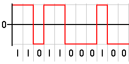
| NRZ–L | Non-return-to-zero level. This is the standard positive logic signal format used in digital circuits. | forces a high level | forces a low level |
| NRZ–M | Non-return-to-zero mark | forces a transition | does nothing (keeps sending the previous level) |
| NRZ–S | Non-return-to-zero space | does nothing (keeps sending the previous level) | forces a transition |
| RZ | Return to zero | goes high for half the bit period and returns to low | stays low for the entire period |
| Biphase–L | Manchester. Two consecutive bits of the same type force a transition at the beginning of a bit period. | forces a negative transition in the middle of the bit | forces a positive transition in the middle of the bit |
| Biphase–M | Variant of Differential Manchester. There is always a transition halfway between the conditioned transitions. | forces a transition | keeps level constant |
| Biphase–S | Differential Manchester used in Token Ring. There is always a transition halfway between the conditioned transitions. | keeps level constant | forces a transition |
| Differential Manchester (Alternative) | Need a Clock, always a transition in the middle of the clock period | is represented by no transition. | is represented by a transition at the beginning of the clock period. |
| Bipolar | The positive and negative pulses alternate. | forces a positive or negative pulse for half the bit period | keeps a zero level during bit period |

Each line code has advantages and disadvantages. Line codes are chosen to meet one or more of the following criteria:
- Minimize transmission hardware
- Facilitate synchronization
- Ease error detection and correction
- Achieve a target spectral density
- Eliminate a DC component
Disparity
[edit]Most long-distance communication channels cannot reliably transport a DC component. The DC component is also called the disparity, the bias, or the DC coefficient. The disparity of a bit pattern is the difference in the number of one bits vs the number of zero bits. The running disparity is the running total of the disparity of all previously transmitted bits.[5] The simplest possible line code, unipolar, gives too many errors on such systems, because it has an unbounded DC component.
Most line codes eliminate the DC component – such codes are called DC-balanced, zero-DC, or DC-free. There are three ways of eliminating the DC component:
- Use a constant-weight code. Each transmitted code word in a constant-weight code is designed such that every code word that contains some positive or negative levels also contains enough of the opposite levels, such that the average level over each code word is zero. Examples of constant-weight codes include Manchester code and Interleaved 2 of 5.
- Use a paired disparity code. Each code word in a paired disparity code that averages to a negative level is paired with another code word that averages to a positive level. The transmitter keeps track of the running DC buildup, and picks the code word that pushes the DC level back towards zero. The receiver is designed so that either code word of the pair decodes to the same data bits. Examples of paired disparity codes include alternate mark inversion, 8b/10b and 4B3T.
- Use a scrambler. For example, the scrambler specified in RFC 2615 for 64b/66b encoding.
Polarity
[edit]Bipolar line codes have two polarities, are generally implemented as RZ, and have a radix of three since there are three distinct output levels (negative, positive and zero). One of the principal advantages of this type of code is that it can eliminate any DC component. This is important if the signal must pass through a transformer or a long transmission line.
Unfortunately, several long-distance communication channels have polarity ambiguity. Polarity-insensitive line codes compensate in these channels.[6][7][8][9] There are three ways of providing unambiguous reception of 0 and 1 bits over such channels:
- Pair each code word with the polarity-inverse of that code word. The receiver is designed so that either code word of the pair decodes to the same data bits. Examples include alternate mark inversion, Differential Manchester encoding, coded mark inversion and Miller encoding.
- differential coding each symbol relative to the previous symbol. Examples include MLT-3 encoding and NRZI.
- Invert the whole stream when inverted syncwords are detected, perhaps using polarity switching
Run-length limited codes
[edit]For reliable clock recovery at the receiver, a run-length limitation may be imposed on the generated channel sequence, i.e., the maximum number of consecutive ones or zeros is bounded to a reasonable number. A clock period is recovered by observing transitions in the received sequence, so that a maximum run length guarantees sufficient transitions to assure clock recovery quality.
RLL codes are defined by four main parameters: m, n, d, k. The first two, m/n, refer to the rate of the code, while the remaining two specify the minimal d and maximal k number of zeroes between consecutive ones. This is used in both telecommunications and storage systems that move a medium past a fixed recording head.[10]
Specifically, RLL bounds the length of stretches (runs) of repeated bits during which the signal does not change. If the runs are too long, clock recovery is difficult; if they are too short, the high frequencies might be attenuated by the communications channel. By modulating the data, RLL reduces the timing uncertainty in decoding the stored data, which would lead to the possible erroneous insertion or removal of bits when reading the data back. This mechanism ensures that the boundaries between bits can always be accurately found (preventing bit slip), while efficiently using the media to reliably store the maximal amount of data in a given space.
Early disk drives used very simple encoding schemes, such as RLL (0,1) FM code, followed by RLL (1,3) MFM code which were widely used in hard disk drives until the mid-1980s and are still used in digital optical discs such as CD, DVD, MD, Hi-MD and Blu-ray using EFM and EFMPLus codes.[11] Higher density RLL (2,7) and RLL (1,7) codes became the de facto standards for hard disks by the early 1990s.[citation needed]
Synchronization
[edit]Line coding should make it possible for the receiver to synchronize itself to the phase of the received signal. If the clock recovery is not ideal, then the signal to be decoded will not be sampled at the optimal times. This will increase the probability of error in the received data.
Biphase line codes require at least one transition per bit time. This makes it easier to synchronize the transceivers and detect errors, however, the baud rate is greater than that of NRZ codes.
Other considerations
[edit]A line code will typically reflect technical requirements of the transmission medium, such as optical fiber or shielded twisted pair. These requirements are unique for each medium, because each one has different behavior related to interference, distortion, capacitance and attenuation.[12]
Common line codes
[edit]- 2B1Q
- 4B3T
- 4B5B
- 6b/8b encoding
- 8b/10b encoding
- 64b/66b encoding
- 128b/130b encoding
- Alternate mark inversion (AMI)
- Coded mark inversion (CMI)
- EFMPlus, used in DVDs
- Eight-to-fourteen modulation (EFM), used in compact discs
- Hamming code
- Hybrid ternary code
- Manchester code and differential Manchester
- Mark and space
- MLT-3 encoding
- Modified AMI codes: B8ZS, B6ZS, B3ZS, HDB3
- Modified frequency modulation, Miller encoding and delay encoding
- Non-return-to-zero (NRZ)
- Non-return-to-zero, inverted (NRZI)
- Pulse-position modulation (PPM)
- Return-to-zero (RZ)
- TC-PAM
Optical line codes
[edit]- Alternate-Phase Return-to-Zero (APRZ)
- Carrier-Suppressed Return-to-Zero (CSRZ)
- Three of Six, Fiber Optical (TS-FO)
See also
[edit]- Physical layer
- Self-synchronizing code and bit synchronization
References
[edit]- ^ K. Schouhamer Immink (2022). "Innovation in Constrained Codes". IEEE Communications Magazine. Retrieved 2022-10-05.
- ^ K. Schouhamer Immink (2001). "A Survey of Codes for Optical Disk Recording". IEEE Journal on Selected Areas in Communications. 19: 751–764. Retrieved 2018-02-05.
- ^ Karl Paulsen. "Coding for Magnetic Storage Mediums" Archived 2014-05-21 at the Wayback Machine.2007.
- ^ Abdullatif Glass; Nidhal Abdulaziz; and Eesa Bastaki (2007), "Slope line coding for telecommunication networks", IEEE International Conference on Signal Processing and Communication, Dubai: IEEE: 1537,
Line codes ... facilitates the transmission of data over telecommunication and computer networks and its storage in multimedia systems.
- ^ Jens Kröger (2014). "Data Transmission at High Rates via Kapton Flexprints for the Mu3e Experiment" (PDF). p. 16. Archived (PDF) from the original on 2022-10-09.
- ^ US 4387366, Peter E. K. Chow., "Code converter for polarity-insensitive transmission systems", published 1983
- ^ David A. Glanzer, "4.7 Polarity", Fieldbus Application Guide ... Wiring and Installation (PDF), Fieldbus Foundation, p. 10, archived (PDF) from the original on 2022-10-09
- ^
George C. Clark Jr.; J. Bibb Cain (2013). Error-Correction Coding for Digital Communications. Springer Science & Business Media. p. 255. ISBN 9781489921741.
When PSK data modulation is used, the potential exists for an ambiguity in the polarity of the received channel symbols. This problem can be solved in one of two ways. First ... a so-called transparent code. ...
- ^
Prakash C. Gupta (2013). Data Communications and Computer Networks. PHI Learning Pvt. Ltd. p. 13. ISBN 9788120348646.
Another benefit of differential encoding is its insensitivity to polarity of the signal. ... If the leads of a twisted pair are accidentally reversed...
- ^ Kees Schouhamer Immink (December 1990). "Runlength-Limited Sequences". Proceedings of the IEEE. 78 (11): 1745–1759. doi:10.1109/5.63306.
A detailed description is furnished of the limiting properties of runlength limited sequences.
- ^ Kees Schouhamer Immink (1995). "EFMPlus: The Coding Format of the MultiMedia Compact Disc". IEEE Transactions on Consumer Electronics. CE-41: 491–497.
A high-density alternative to EFM is described.
- ^ Dong, Jielin (2007). Network Dictionary. Javvin Technologies Inc. p. 284. ISBN 9781602670006.
 This article incorporates public domain material from Federal Standard 1037C. General Services Administration. Archived from the original on 2022-01-22. (in support of MIL-STD-188).
External links
[edit]- Line Coding Lecture No. 9
- Line Coding in Digital Communication
- CodSim 2.0: Open source simulator for Digital Data Communications Model at the University of Malaga written in HTML
Line coding (digital baseband transmission) | ||
|---|---|---|
| Main articles | | |
| Basic line codes | ||
| Extended line codes | ||
| Optical line codes | ||
Line code
View on GrokipediaFundamentals of Line Coding
Definition and Purpose
Line coding refers to the process of transforming sequences of binary data into digital signals suitable for transmission over physical communication channels, such as metallic wires or optical fibers, or for storage on media like magnetic tapes. This conversion ensures that the digital information can be reliably propagated while accommodating the limitations of the transmission medium.[3][2] The primary purposes of line coding include enabling accurate signal detection at the receiver by shaping the waveform to distinguish bits clearly, maintaining DC balance to avoid baseline wander that could distort long sequences of identical bits, facilitating clock synchronization for timing recovery without separate clock lines, and optimizing spectral properties to minimize required bandwidth and control power distribution across frequencies. These functions address key challenges in digital transmission, such as signal degradation over distance and interference from the channel.[4][5][6] Line coding techniques originated in the 19th century with early telegraphy systems using basic on-off keying schemes such as Morse code. They evolved in the 20th century through the development of pulse code modulation for telephony in 1937 by Alec Reeves, leading to more efficient handling of voice and data signals.[7][8] By the mid-20th century, it advanced into standardized digital systems, with the International Telecommunication Union (ITU) issuing recommendations such as G.703 in 1972 (and subsequent revisions) that specify line coding formats for synchronous digital hierarchy interfaces to ensure interoperability in global networks.[9] Effective line codes must meet key requirements including spectral efficiency to utilize bandwidth economically, power efficiency to reduce energy consumption for a given data rate and error performance, and robustness to noise and interference for reliable operation in adverse environments. These attributes prioritize the balance between transmission reliability and resource constraints in practical deployments.[1][2]Basic Encoding Principles
Line coding fundamentally involves the process of mapping binary data sequences—typically represented as streams of 0s and 1s—into analog waveforms suitable for transmission over a physical medium, such as a twisted-pair cable or optical fiber. This mapping transforms digital bits into voltage levels, pulses, or transitions that propagate along the transmission line while preserving the information content. The encoder at the transmitter side converts each bit into a corresponding signal element, often using pulse shaping to control the waveform's duration and amplitude, ensuring compatibility with the channel's bandwidth limitations and noise characteristics.[3][5] Waveforms in line coding are classified based on their polarity and timing behavior. Unipolar formats employ only positive voltage levels (or a single polarity), where a logical 1 might be represented by a positive voltage and a 0 by zero voltage, as seen in unipolar non-return-to-zero (NRZ) schemes. Bipolar formats, in contrast, utilize both positive and negative voltage levels to encode bits, enhancing signal detection by providing greater contrast; for example, in bipolar NRZ, a 1 could alternate between +V and -V, while a 0 remains at zero. Additionally, return-to-zero (RZ) formats return the signal to a zero level during a portion of each bit period (typically mid-bit), which aids in clock extraction but doubles the required bandwidth compared to NRZ formats that maintain the level throughout the bit interval without returning to zero.[10][3] In baseband transmission, line coding adapts basic modulation principles such as amplitude shifts, where bit values determine the pulse height, or phase transitions for encoding changes between levels. These techniques operate at low frequencies near DC, avoiding carrier modulation to minimize complexity; for instance, pulse amplitude modulation (PAM) assigns discrete amplitude levels to bits, shaping the power spectral density to suppress low-frequency components that could cause baseline wander. Frequency shifts are less common in pure line coding but may involve pulse rate adjustments to embed timing information.[5][3] A simple binary encoding example illustrates these principles: in unipolar NRZ, a logical 1 is mapped to a high voltage (+V) sustained for the entire bit duration, while a 0 is mapped to low voltage (0V), producing a rectangular waveform sequence. Signal integrity is evaluated using eye patterns, which overlay multiple bit transitions to visualize the received signal's clarity; a wide-open eye indicates low intersymbol interference and noise margins, whereas closure suggests degradation from bandwidth constraints or distortions in the line-coded waveform.[10][5]Essential Properties
Disparity and DC Balance
In line codes, disparity refers to the running count of the difference between the number of 1s and 0s (or positive and negative pulses in bipolar schemes) accumulated over a sequence of codewords, serving as a measure of signal imbalance. This running disparity tracks the cumulative deviation to monitor and control the overall balance in the encoded stream.[11] DC balance, characterized by maintaining an average disparity of zero, is essential in transmission systems to eliminate the DC component of the signal, thereby preventing distortion in AC-coupled circuits where capacitors block steady-state voltages. Without balance, prolonged sequences of identical bits can cause baseline wander—a gradual shift in the signal's reference level due to high-pass filtering effects—leading to errors in receiver detection thresholds. The disparity for a given sequence is often normalized as , where a value of indicates perfect balance and corresponds to a spectral null at DC frequency.[12][13] To achieve DC balance, block coding techniques partition data into fixed-length groups and map them to codewords selected based on the current running disparity, ensuring the transmitted symbols have an equal or compensating number of 1s and 0s. For instance, the seminal 8b/10b code, developed by Widmer and Franaszek, encodes 8-bit data into 10-bit symbols with individual disparities of 0, +2, or -2; the encoder alternates symbol polarity to invert the disparity when necessary, keeping the running disparity bounded and the long-term average at zero. Scrambling methods, such as those used in Ethernet standards, apply pseudo-random sequences to data before encoding, statistically distributing 1s and 0s to suppress low-frequency components without fixed block structures.[14][15] As an example, consider a simplified sequence in an 8b/10b-like scheme starting with running disparity RD = 0: a codeword with four 1s and six 0s yields a block disparity of -2, updating RD to -2; the next codeword is then chosen or complemented to have +2 disparity, restoring RD to 0 and demonstrating cumulative control. Over long-term sequences, maximum allowable disparity limits—such as ±4 in certain block codes—constrain excursions to guarantee bounded low-frequency content and maintain the DC spectral null, minimizing wander even in extended transmissions.[14]Polarity Considerations
In line coding, polarity refers to the assignment of voltage levels to represent binary states, where unipolar schemes employ a single polarity—typically zero for one state and a positive voltage for the other—while bipolar schemes utilize both positive and negative voltages alongside zero.[3] Unipolar encoding, such as unipolar NRZ, maps binary 0 to 0 V and binary 1 to +V, resulting in a persistent DC component that can cause baseline wander and ambiguity in decoding if the received signal drifts due to channel imperfections or noise.[2] This ambiguity heightens error susceptibility, as a gradual DC offset might flip perceived 0s into 1s or vice versa without violating timing constraints.[2] Bipolar schemes mitigate these issues by alternating polarities for successive 1s, enhancing noise rejection through differential-like properties that cancel common-mode interference, particularly effective in balanced transmission media.[16] The alternating nature suppresses low-frequency noise and improves overall signal integrity by distributing energy across positive and negative domains, reducing the impact of induced noise from external sources.[16] A prominent example is Alternate Mark Inversion (AMI), a bipolar format where binary 0s (spaces) are encoded as 0 V and binary 1s (marks) as pulses alternating between +V and -V on successive occurrences.[3] This strict alternation rule enables inherent error detection: a bipolar violation—such as two consecutive marks sharing the same polarity—signals a transmission error, allowing receivers to flag and potentially correct or discard affected bits without additional overhead.[17] In transmission over twisted-pair lines, bipolar polarity schemes like AMI reduce crosstalk by minimizing unbalanced electromagnetic coupling between adjacent pairs, as the zero-mean signal limits near-end and far-end interference.[2] This balanced approach also boosts signal-to-noise ratio (SNR) by rejecting common-mode noise more effectively than unipolar signals.[16] These polarity strategies complement DC balance objectives by inherently limiting long-term voltage offsets through alternation.[3]Run-Length Limitations
Run-length limited (RLL) codes, denoted as (d,k)-RLL, are binary encoding schemes that constrain the lengths of consecutive identical symbols, specifically limiting runs of zeros between successive ones to a minimum of d and a maximum of k.[18] This notation defines a constrained channel where sequences violating the run-length bounds are invalid, ensuring controlled symbol patterns in line-coded signals.[18] The primary purpose of these constraints in line coding is to optimize timing recovery and spectral properties of the transmitted signal. The d parameter enforces a minimum separation between transitions to mitigate inter-symbol interference, while the k parameter caps the maximum run length to prevent prolonged absence of transitions that could hinder clock extraction; together, they shape the power spectrum by reducing low-frequency energy, which minimizes baseline wander and interference in bandwidth-limited channels.[19][18] Mathematically, the constraints dictate a minimum transition density of transitions per bit, as the longest allowable run of k zeros followed by a one yields this periodic lower bound.[18] The channel capacity, analogous to Shannon's limit but for constrained inputs, is , where is the largest eigenvalue of the adjacency matrix representing the finite-state model of valid transitions; this bound quantifies the supremum of achievable rates in bits per symbol for the (d,k)-RLL system.[18] For example, a (0,3)-RLL code allows zero to three consecutive zeros between ones, promoting a high transition density for robust timing in high-speed links.[18] In block implementations, the coding overhead manifests as a rate of , where M is the number of valid n-bit codewords, reducing the effective data throughput relative to uncoded binary transmission.[18] Some (d,k)-RLL designs further integrate disparity controls to achieve DC balance alongside run-length constraints.[19]Synchronization Aspects
Clock Recovery Mechanisms
Clock recovery is essential in line-coded digital communication systems, where timing information must be embedded within the data signal itself due to the absence of a dedicated clock line. This embedded approach allows for efficient single-channel transmission but introduces challenges such as clock jitter, which arises from noise and distortions in the channel, and clock drift, caused by differences in oscillator frequencies between transmitter and receiver. These impairments can lead to sampling errors if the recovered clock phase deviates significantly from the data transitions.[20] Common techniques for clock recovery include phase-locked loops (PLLs) for continuous phase alignment and edge detection methods for signals with frequent transitions. In PLL-based recovery, a voltage-controlled oscillator (VCO) adjusts its phase to match the incoming data edges, using a phase detector to compare timing and a loop filter to stabilize the response; this method effectively tracks ongoing data streams while suppressing high-frequency jitter. For line codes like Manchester encoding, which guarantee a transition in every bit period, simpler edge detection circuits can extract the clock by identifying mid-bit transitions, enabling robust synchronization without complex analog components.[21][22] Quantitative analysis of clock recovery performance often focuses on jitter tolerance, defined as the maximum allowable phase error before bit errors occur. For binary signaling, the maximum phase error is typically limited to radians to ensure the sampling point remains within the eye opening, preventing decision errors at the receiver. PLL lock time, the duration required for the loop to settle within a specified error band after initial acquisition, can be estimated using the second-order system settling time approximation , where is the damping factor and is the natural frequency; this highlights the trade-off between loop bandwidth and acquisition speed.[23][24] The choice of line code significantly influences clock recovery efficacy, as higher transition density provides more reference edges for phase locking, thereby reducing the probability of clock slips during long sequences of identical bits. Preamble patterns, consisting of alternating bits or specific sequences at the start of a transmission, facilitate initial alignment by offering a burst of transitions to quickly acquire lock before the data payload begins. Line codes that limit maximum run lengths further support recovery by ensuring periodic transitions, minimizing the risk of prolonged phase uncertainty.[20][25]Self-Synchronizing Features
Self-synchronizing line codes enable the recovery of bit boundaries directly from transitions embedded in the data signal itself, eliminating the need for prolonged preamble sequences or separate clock references to prevent bit slips. In such codes, the encoding scheme ensures sufficient signal changes—arising from data-dependent or guaranteed transitions—that allow the receiver's timing circuits to align with the transmitter's bit clock after a short acquisition period. This intrinsic timing information is crucial for maintaining synchronization in asynchronous or burst-mode transmissions, where external aids may be impractical.[3] A key characteristic of these codes is the enforcement of transitions at regular intervals, often every few bits, to provide reliable cues for clock extraction. For instance, differential Manchester encoding features a transition in the middle of each bit period for clock synchronization, with a transition at the start of the bit period indicating a binary 0 and its absence indicating a binary 1, ensuring at least one change per bit and facilitating rapid self-alignment.[26] These features offer significant advantages, particularly in bursty traffic scenarios common to packet-switched networks, by minimizing preamble overhead and enabling quick resynchronization with just a handful of bits. However, codes exhibiting low transition probabilities—such as non-return-to-zero (NRZ) formats during extended runs of identical symbols—may still necessitate auxiliary clock recovery hardware, like phase-locked loops, to avoid prolonged lock times. Limitations arise in low-activity patterns, where sparse transitions increase vulnerability to timing jitter.[3] Synchronization loss can be detected by observing the absence of transitions exceeding the code's maximum run-length limit, which signals potential bit slip and prompts a resynchronization attempt. In run-length limited designs, this threshold—often capped at 3 to 5 bits—serves as a direct indicator, allowing the system to revert to a preamble or reinitialize timing extraction without widespread data corruption. Such monitoring integrates seamlessly with the code's structure, enhancing robustness in noisy channels.[3]Categories of Line Codes
Binary and Bipolar Codes
Binary line codes represent digital data using two voltage levels, typically for baseband transmission, while bipolar variants employ three levels to enhance certain properties. Non-return-to-zero (NRZ) codes maintain a constant voltage level throughout each bit period, making them simple to implement but prone to certain limitations.[27] NRZ-level (NRZ-L) encoding assigns a positive voltage to binary 0 and a negative voltage to binary 1, or vice versa, without returning to zero between bits. This scheme supports high data rates due to its straightforward structure but introduces a significant DC component, especially in long sequences of identical bits, which can cause baseline wander in AC-coupled systems. Additionally, synchronization is challenging because extended runs of 0s or 1s produce no transitions, complicating clock recovery at the receiver.[27] NRZ-inverted (NRZ-I) addresses some synchronization issues by defining a transition at the start of each bit period for binary 1, while binary 0 causes no change from the previous level. This results in better transition density for data with frequent 1s, reducing the risk of prolonged no-transition periods compared to NRZ-L, though it still suffers from DC imbalance and sensitivity to errors in the initial state.[27] Return-to-zero (RZ) codes mitigate some NRZ drawbacks by using a pulse width of half the bit period, returning the signal to zero midway through each bit. For binary 1, a pulse (positive or negative) occupies the first half, followed by zero in the second half; binary 0 remains at zero throughout. This design aids synchronization through regular mid-bit transitions and reduces DC content by ensuring the signal returns to baseline, but it requires twice the bandwidth of NRZ due to the higher transition rate. RZ is particularly advantageous in environments needing clear pulse separation, though its complexity increases implementation costs.[27] Bipolar codes extend binary signaling by alternating polarities for marks (1s), using three levels: positive, negative, and zero. Alternate mark inversion (AMI) encodes binary 0 as zero voltage and binary 1 as alternating positive and negative pulses, adhering to polarity rules that prevent consecutive marks of the same polarity. This eliminates the DC component inherent in NRZ, as the average voltage over time approaches zero, and provides good synchronization during sequences rich in 1s due to frequent transitions. However, long runs of 0s cause no transitions, leading to potential loss of timing and reduced ones density, which can degrade performance in digital hierarchies like T1 lines.[2] To address the zeros problem in AMI, bipolar with 8-zero substitution (B8ZS) substitutes any sequence of eight consecutive 0s with a specific pattern: 000+-0-+, where + and - are bipolar violations (two consecutive pulses of the same polarity). This insertion maintains the required ones density for reliable transmission and allows error detection via the intentional violations, which do not occur in normal AMI encoding. B8ZS is standardized for T1/DS1 interfaces, ensuring compatibility while preserving bandwidth efficiency.[2] The following table compares key properties of representative binary and bipolar codes:| Code | Bandwidth Requirement | DC Balance | Synchronization Capability |
|---|---|---|---|
| NRZ-L | Low (bit rate) | Poor | Poor (no transitions in runs) |
| NRZ-I | Low (bit rate) | Moderate | Moderate (transitions on 1s) |
| RZ | High (2x bit rate) | Good | Good (mid-bit transitions) |
| AMI | Low (bit rate) | Excellent | Good for 1s, poor for 0 runs |