Hubbry Logo
Isenthalpic processIsenthalpic processMain
Open search
Isenthalpic process
Community hub
Isenthalpic process
logo
8 pages, 0 posts
0 subscribers
Be the first to start a discussion here.
Isenthalpic process
Isenthalpic process
from Wikipedia

An isenthalpic process or isoenthalpic process is a process that proceeds without any change in enthalpy, H; or specific enthalpy, h.[1]

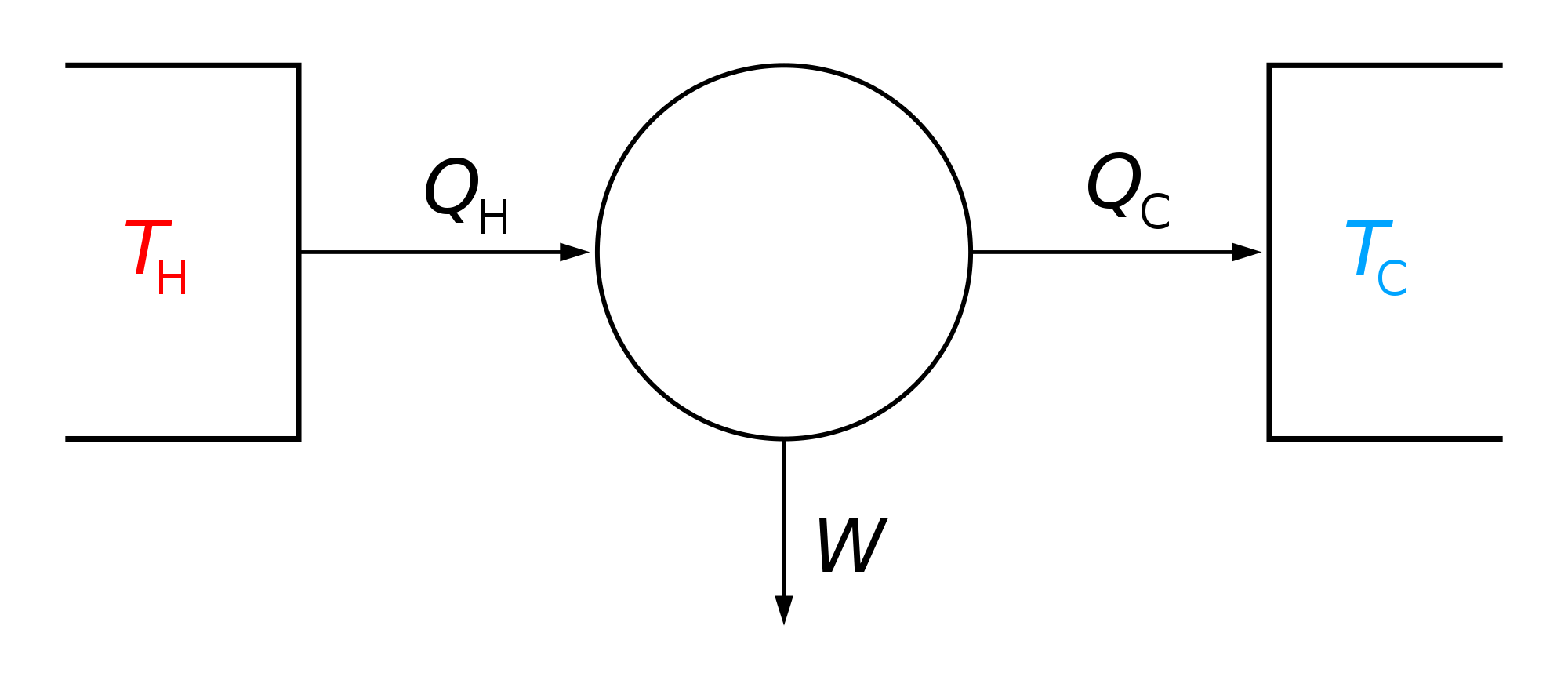
If a steady-state, steady-flow process is analysed using a control volume, everything outside the control volume is considered to be the surroundings.[2]

Definition and formula

[edit]

Such a process will be isenthalpic if there is no transfer of heat to or from the surroundings, no work done on or by the surroundings, and no change in the kinetic energy of the fluid.[3] This is a sufficient but not necessary condition for isoenthalpy. The necessary condition for a process to be isoenthalpic is that the sum of each of the terms of the energy balance other than enthalpy (work, heat, changes in kinetic energy, etc.) cancel each other, so that the enthalpy remains unchanged. For a process in which magnetic and electric effects (among others) give negligible contributions, the associated energy balance can be written as


If then it must be that

Where K is kinetic energy, u is internal energy, Q is heat, W is work, h is enthalpy, P is pressure, and V is volume.

Example

[edit]

The throttling process is a good example of an isoenthalpic process in which significant changes in pressure and temperature can occur to the fluid, and yet the net sum of the associated terms in the energy balance is null, thus rendering the transformation isoenthalpic. The lifting of a relief (or safety) valve on a pressure vessel is an example of throttling process. The specific enthalpy of the fluid inside the pressure vessel is the same as the specific enthalpy of the fluid as it escapes through the valve.[3] With a knowledge of the specific enthalpy of the fluid and the pressure outside the pressure vessel, it is possible to determine the temperature and speed of the escaping fluid.

In an isenthalpic process:

  • ,
  • .

Isenthalpic processes on an ideal gas follow isotherms, since .

See also

[edit]

References

[edit]
Revisions and contributorsEdit on WikipediaRead on Wikipedia
from Grokipedia
An isenthalpic process, also known as an isoenthalpic process, is a in which the of the system remains constant, meaning there is no change in (ΔH = 0 or dh = 0). This condition typically arises in steady-state, open-flow systems where is absent (adiabatic, Q = 0), no shaft work is performed (W = 0), and changes in kinetic and are negligible, leading to upstream and downstream enthalpies being equal (h_1 = h_2). Such processes are inherently irreversible and are characterized by a across a restriction, with no shaft work or external input. The most prominent example is the throttling process, where a flows through a , porous plug, or orifice, resulting in a sudden expansion and potential phase change, such as in wet where increases slightly (e.g., from 87% to 87.4% upon throttling from 1.15 MPa to 1.0 MPa at around 180–186°C). In gases, this manifests as the Joule-Thomson effect, where the change upon expansion depends on the Joule-Thomson coefficient (μ_JT = (∂T/∂P)_H), causing cooling for most real gases at (e.g., CO₂, N₂) but heating for and above their inversion temperatures. For ideal gases, the process is isothermal since depends only on (h = u + Pv ≈ f(T)), but real gases deviate due to intermolecular forces. Isenthalpic processes are fundamental in engineering applications, particularly in vapor-compression refrigeration cycles, where the expansion valve throttles high-pressure liquid to low-pressure vapor-liquid , enabling efficient cooling without work input during expansion. They also play a critical role in liquefaction and cryogenic processes, such as in LNG production, by facilitating controlled cooling through successive throttling stages to achieve low temperatures. In , throttling is used for pressure regulation in steam systems, maintaining balance to predict downstream states like and phase from known upstream conditions and outlet pressure. Analysis often employs enthalpy-specific volume (h-s) diagrams or steam tables to quantify outcomes, underscoring the process's utility in predicting fluid behavior under constant constraints.

Fundamentals

Definition

An isenthalpic process is a in which the of the remains constant, denoted as ΔH=0\Delta H = 0, irrespective of variations in , , or . This constancy implies that the total heat content at constant does not change, distinguishing it from other processes like isobaric or isothermal ones where different properties are held invariant. Enthalpy, HH, is defined as the sum of the internal energy UU of the system and the product of PP and VV, expressed as H=U+PVH = U + PV. This formulation is particularly significant in open systems or flow processes, where accounts for both the internal energy transported by the fluid and the flow work associated with pressure-volume interactions across system boundaries. The term "isenthalpic" originates from the Greek prefix "iso-" meaning "equal" combined with "enthalpy," a word derived from "en-" (in) and "thalpein" (to heat), reflecting its relation to content. First recorded in 1925 in , it was formalized in early 20th-century building on 19th-century foundational concepts, though synonymous phrases like "constant enthalpy process" are also used interchangeably in technical contexts.

Thermodynamic Context

In the context of open thermodynamic systems, the isenthalpic process derives from of applied to steady-state flow conditions, where the differential change in satisfies dh = δq + v dP for specific quantities, with δq representing per unit mass and v dP the flow work term. This relation highlights how constant (dh = 0) implies a balance where any addition is offset by pressure-volume work, often resulting in negligible net in practical scenarios. itself, defined as H = + PV, naturally emerges in open-system analyses to account for both and the energy associated with flow across system boundaries. Isenthalpic processes are particularly applicable to steady-state flow in devices like valves, where flow rates are constant and changes in kinetic or potential are negligible, leading to the steady-flow energy equation simplifying to h_1 = h_2 under adiabatic conditions with no shaft work. These processes typically occur in control volumes where fluid expands through restrictions, maintaining overall without external work input beyond flow work. Such processes are inherently irreversible due to dissipative effects like and turbulent mixing, rather than proceeding reversibly, and they assume no (δq = 0), which aligns with adiabatic but non-quasistatic conditions where increases. The ideality relies on neglecting variations and assuming uniform properties, though real implementations often involve minor deviations from perfect steadiness. In single-phase systems, isenthalpic processes maintain uniform composition, potentially leading to shifts via intermolecular forces, as seen in real gases. Conversely, in multiphase systems, the process can accommodate phase transitions—such as or —while preserving total , enabling equilibrium calculations across liquid-vapor boundaries without net enthalpy alteration. This behavior is critical for systems where occurs under constant enthalpy constraints.

Mathematical Formulation

Enthalpy Conservation

In an isenthalpic process, the specific remains constant between the initial and final states, expressed as h2=h1h_2 = h_1 or equivalently Δh=0\Delta h = 0, where subscripts 1 and 2 denote the upstream and downstream conditions, respectively. This conservation arises in steady-flow scenarios, such as fluid expansion through a restriction, where no or shaft work occurs. The derivation follows from the first law of thermodynamics applied to a under steady-flow conditions. The steady-flow energy equation states that for a unit mass of fluid, q+w=(h2+v222+gz2)(h1+v122+gz1)q + w = (h_2 + \frac{v_2^2}{2} + g z_2) - (h_1 + \frac{v_1^2}{2} + g z_1), where qq is per unit mass, ww is work per unit mass, vv is velocity, and zz is elevation. For an adiabatic throttling process (q=0q = 0), with no shaft work (w=0w = 0) and negligible changes in kinetic and potential energy (Δ(v22+gz)0\Delta(\frac{v^2}{2} + g z) \approx 0), the equation simplifies to h2=h1h_2 = h_1. This form incorporates the flow work term PvPv into the definition h=u+Pvh = u + Pv, where uu is specific , ensuring the energy balance holds without explicit accounting for . Enthalpy is a thermodynamic state function, depending solely on the system's state variables (such as and ) rather than the process path. Consequently, the change Δh\Delta h is path-independent, allowing isenthalpic processes to be represented as constant-enthalpy contours on diagrams like the enthalpy-entropy (H-S, or Mollier) chart or pressure-enthalpy (P-H) diagram, regardless of the specific from state 1 to state 2. To determine properties in real-gas isenthalpic processes, thermodynamic tables or Mollier diagrams are employed. Starting from known initial conditions (P1,h1P_1, h_1), the final state (P2,h2=h1P_2, h_2 = h_1) is located by tracing the constant-enthalpy line on the Mollier diagram, yielding values such as the final T2T_2. These tools account for non-ideal behavior, providing accurate interpolations for fluids like or refrigerants where equation-of-state data are tabulated.

Process Characteristics

In an isenthalpic process, the temperature behavior varies distinctly between ideal and real gases due to differences in their thermodynamic properties. For an , enthalpy is a function solely of , so maintaining constant implies no change in , making the process effectively isothermal. In contrast, real gases exhibit changes arising from intermolecular forces during reduction; cooling occurs via the Joule-Thomson effect when the initial is below the inversion , while heating predominates above it. These deviations stem from attractive and repulsive interactions that alter the balance without or work. Isenthalpic processes are always irreversible, leading to a positive change in (ΔS > 0) that signifies increased molecular disorder. This entropy generation arises from dissipative mechanisms, such as viscous friction and turbulent mixing, inherent to the process dynamics. The irreversibility ensures that the system's available energy decreases, even as total remains conserved. Regarding and , an isenthalpic process typically involves a substantial , with a corresponding increase in for gases, driven by the relation H = U + pV under constant . Unlike controlled expansions that produce work, no net work is performed or extracted, resulting in purely dissipative energy redistribution.

Practical Applications

Throttling and Expansion

Throttling refers to an irreversible expansion process in which a undergoes a sudden as it passes through a restriction, such as a porous plug or , while maintaining constant due to the absence of and work input. This process occurs under steady-flow conditions, where the upstream exceeds the downstream , leading to a non-equilibrium expansion characterized by frictional within the . Common devices that facilitate throttling include capillary tubes, orifice plates, and safety valves in pipelines. Capillary tubes, typically narrow copper passages, restrict flow to achieve precise pressure reduction in compact systems. Orifice plates, thin barriers with a central hole inserted into pipelines, create a controlled pressure drop for flow measurement or regulation. Safety valves, designed for emergency pressure relief, open abruptly to allow fluid discharge, exemplifying throttling in high-pressure industrial applications. In , throttling is used for regulation in systems, helping maintain balance to predict downstream states like and phase from known upstream conditions and outlet . The energy balance in a throttling process derives from the steady-flow energy equation for a , where there is no shaft work and negligible , resulting in the conservation of : h1+c122=h2+c222h_1 + \frac{c_1^2}{2} = h_2 + \frac{c_2^2}{2}, with cc denoting . In typical setups, kinetic energy changes are small compared to , approximating the process as isenthalpic (h1h2h_1 \approx h_2), with energy dissipation occurring through viscous friction and turbulence, converting into without net change for ideal gases. This irreversibility manifests as generation due to the uncontrolled expansion. Experimental verification of enthalpy constancy in throttling employs the porous plug apparatus, a setup originally developed to study behavior. In this device, a tube is divided by a porous plug, and gas is forced at constant from a high-pressure upstream chamber (pressure P1P_1, volume V1V_1) to a low-pressure downstream chamber (pressure P2P_2, volume V2V_2). Pistons maintain steady pressures, performing work P1V1P2V2P_1 V_1 - P_2 V_2 on the , while adiabatic insulation ensures no exchange. Measurements of changes balance against this work, confirming that H=U+PVH = U + PV remains invariant across the plug.

Refrigeration and Cryogenics

In systems, the serves as the key component for the isenthalpic expansion of the , where high-pressure is depressurized to , resulting in partial and a significant drop that enables heat absorption from the cooled space. This process maintains constant across the , transforming the into a low-temperature -vapor that enters the at a reduced , typically achieving cooling effects suitable for or commercial applications. The simplicity of this adiabatic, irreversible expansion makes it integral to standard cycles, where the , such as R-134a, undergoes flashing that cools the by typically 40–70 K depending on operating pressures and system conditions. In cryogenic liquefaction, the Linde process employs repeated isenthalpic throttling through Joule-Thomson to separate and liquefy air components, cooling streams to below -140°C by exploiting intermolecular forces in real gases during expansion. Developed by in 1895, this method compresses air to around 60 bar, precools it via heat exchange, and throttles it across a , where the temperature drop—approximately 0.25°C per bar—leads to partial , with non-condensable gases recycled for further cooling in a countercurrent exchanger. Repeated cycles in modern units achieve cryogenic below -100°C, enabling efficient production of and for industrial use. Isenthalpic throttling is favored for its mechanical simplicity and lack of , but it is less efficient than isentropic expansion due to inherent irreversibilities that generate and reduce the (COP) in cycles. In vapor-compression systems, throttling losses account for a significant portion of total cycle inefficiencies, often lowering COP by 10-20% compared to expander-based alternatives, as the process does not recover expansion work and results in higher input requirements. Despite these drawbacks, its robustness and low cost justify its use in most practical systems, where COP values typically range from 2-4 for common refrigerants, prioritizing reliability over maximal efficiency. In modern (LNG) production, isenthalpic throttling via Joule-Thomson valves is applied in small-scale plants to liquefy at -159°C to -162°C, offering a cost-effective alternative to complex turbo-expanders for on-site facilities like fueling stations. For superconducting systems, 21st-century advancements in micro-throttling Joule-Thomson cryocoolers have enabled compact, vibration-free cooling to below 80 K for space applications, such as detectors on satellites. These developments, including open-cycle designs tested since 2010, enhance efficiency through optimized heat exchangers and throttling geometries, supporting missions like the Planck while minimizing mass and power needs, with micromachined orifices achieving cooling powers of around 10 W at temperatures.

Joule-Thomson Effect

The Joule-Thomson effect refers to the change observed in a during an isenthalpic throttling process, where the gas expands through a porous plug or valve without heat transfer or work done. This deviation from behavior arises due to intermolecular forces, leading to either cooling or heating depending on the conditions. The effect is quantified by the Joule-Thomson coefficient, defined as μJT=(TP)H\mu_{JT} = \left( \frac{\partial T}{\partial P} \right)_H, which measures the rate of change with pressure at constant . The phenomenon was discovered through experiments conducted by and William Thomson (later ) between 1852 and 1862, where they observed a temperature drop in air expanding from high to low pressure through a . Their work, initially reported in 1852 to the British Association for the Advancement of Science, demonstrated that real gases cool upon expansion under typical conditions, contrasting with the zero temperature change for ideal gases. Modern measurements confirm these findings, with detailed data for various gases including , which exhibits anomalous heating at due to its negative μJT\mu_{JT}. The Joule-Thomson coefficient can be derived thermodynamically using the chain rule and Maxwell relations, yielding μJT=T(VT)PVCP\mu_{JT} = \frac{T \left( \frac{\partial V}{\partial T} \right)_P - V}{C_P}, where CPC_P is the at constant pressure, TT is , VV is , and the partial derivative reflects the coefficient. For ideal gases, (VT)P=VT\left( \frac{\partial V}{\partial T} \right)_P = \frac{V}{T}, making μJT=0\mu_{JT} = 0; however, in real gases, deviations stem from intermolecular and repulsions modeled by equations like the , where the attractive term aa contributes to cooling by hindering molecular separation. This linkage to van der Waals forces explains why μJT\mu_{JT} is positive (cooling) for most gases at and moderate pressures. The inversion curve represents the locus of points in the pressure-temperature plane where μJT=0\mu_{JT} = 0, demarcating regions of cooling (μJT>0\mu_{JT} > 0) from heating (μJT<0\mu_{JT} < 0). Above the inversion temperature, the gas heats upon expansion, while below it, cooling occurs. For carbon dioxide, the maximum inversion temperature is approximately 1500 K, allowing significant cooling under ambient conditions relevant to industrial processes.

Comparisons with Other Processes

An isenthalpic process, characterized by constant enthalpy (ΔH = 0), differs fundamentally from an , which maintains constant entropy (ΔS = 0) and is both adiabatic and reversible. In an isenthalpic process, entropy increases (ΔS > 0) due to its irreversible nature, resulting in no net work output, whereas an isentropic process enables maximum work extraction, such as in ideal turbines or compressors. This contrast highlights the efficiency loss in isenthalpic expansions, where irreversibilities like or sudden drops prevent reversible energy conversion. For ideal gases, an isenthalpic process coincides with an because depends solely on (H = C_p T), so ΔH = 0 implies ΔT = 0. However, for real gases, deviations arise due to intermolecular forces, leading to temperature changes via the Joule-Thomson effect, unlike purely es that require to maintain constant . The table below compares key properties for a pressure reduction process in an ideal gas context:
PropertyIsenthalpic Process
Change (ΔH)00 (for ideal gas)
Change (ΔT)0 (ideal gas)0
Entropy Change (ΔS)> 0 (irreversible)≥ 0
(Q)0= -W (to maintain T)
Work (W)0< 0 (expansion)
This equivalence breaks for real gases, where isenthalpic processes often involve cooling or heating without external heat input. Both isenthalpic and es involve no (Q = 0), but they diverge in energy balance: an adiabatic process satisfies ΔU = W, allowing work input or output that alters , while an isenthalpic process enforces ΔH = 0, or ΔU + Δ(PV) = 0, typically with no shaft work and irreversibilities dissipating as increase. Thus, isenthalpic processes, often realized in throttling devices, represent a of irreversible adiabatic expansions without useful work recovery. Isenthalpic processes are selected in applications prioritizing simplicity and low cost, such as throttling valves in cycles, where no are needed despite lower compared to isentropic expansions in turbines that maximize work output. In contrast, isentropic processes are preferred for high-performance energy conversion, like in gas turbines, to minimize generation and enhance overall cycle .

References

Add your contribution
Related Hubs
User Avatar
No comments yet.