

| JPEG | |
|---|---|
 | |
 A photo of a European wildcat with the compression rate, and associated losses, decreasing from left to right | |
| Filename extension | .jpg, .jpeg, .jpe.jif, .jfif, .jfi |
| Internet media type |
image/jpeg |
| Type code | JPEG |
| Uniform Type Identifier (UTI) | public.jpeg |
| Magic number | ff d8 ff |
| Developed by | Joint Photographic Experts Group, IBM, Mitsubishi Electric, AT&T, Canon Inc.[1] |
| Initial release | 18 September 1992 |
| Type of format | Lossy image compression format |
| Extended to | JPEG 2000 |
| Standard | ISO/IEC 10918, ITU-T T.81, ITU-T T.83, ITU-T T.84, ITU-T T.86 |
| Website | jpeg |

JPEG (/ˈdʒeɪpɛɡ/ JAY-peg, short for Joint Photographic Experts Group and sometimes retroactively referred to as JPEG 1)[2][3] is a commonly used method of lossy compression for digital images, particularly for those images produced by digital photography. The degree of compression can be adjusted, allowing a selectable trade off between storage size and image quality. JPEG typically achieves 10:1 compression with noticeable, but widely agreed to be acceptable perceptible loss in image quality.[4] Since its introduction in 1992, JPEG has been the most widely used image compression standard in the world,[5][6] and the most widely used digital image format, with several billion JPEG images produced every day as of 2015.[7]
The Joint Photographic Experts Group created the standard in 1992,[8] based on the discrete cosine transform (DCT) algorithm.[9][10] JPEG was largely responsible for the proliferation of digital images and digital photos across the Internet and later social media.[11][circular reference] JPEG compression is used in a number of image file formats. JPEG/Exif is the most common image format used by digital cameras and other photographic image capture devices; along with JPEG/JFIF, it is the most common format for storing and transmitting photographic images on the World Wide Web.[12] These format variations are often not distinguished and are simply called JPEG.
The MIME media type for JPEG is "image/jpeg", except in older Internet Explorer versions, which provide a MIME type of "image/pjpeg" when uploading JPEG images.[13] JPEG files usually have a filename extension of "jpg" or "jpeg". JPEG/JFIF supports a maximum image size of 65,535×65,535 pixels,[14] hence up to 4 gigapixels for an aspect ratio of 1:1. In 2000, the JPEG group introduced a format intended to be a successor, JPEG 2000, but it was unable to replace the original JPEG as the dominant image standard.[15]
History
[edit]Background
[edit]The original JPEG specification published in 1992 implements processes from various earlier research papers and patents cited by the CCITT (now ITU-T) and Joint Photographic Experts Group.[1]
The basis for JPEG's lossy compression algorithm is the discrete cosine transform (DCT),[9][10] which was first proposed by Nasir Ahmed as an image compression technique in 1972.[16][10] Ahmed published the DCT algorithm with T. Natarajan and K. R. Rao in a 1974 paper,[17] which is cited in the JPEG specification.[9]
The JPEG specification cites patents from several companies. The following patents provided the basis for its arithmetic coding algorithm.[1]
- IBM
- U.S. patent 4,652,856 – 4 February 1986 – Kottappuram M. A. Mohiuddin and Jorma J. Rissanen – Multiplication-free multi-alphabet arithmetic code
- U.S. patent 4,905,297 – 27 February 1990 – G. Langdon, J. L. Mitchell, W. B. Pennebaker, and Jorma J. Rissanen – Arithmetic coding encoder and decoder system
- U.S. patent 4,935,882 – 19 June 1990 – W. B. Pennebaker and J. L. Mitchell – Probability adaptation for arithmetic coders
- Mitsubishi Electric
- JP H02202267 (1021672) – 21 January 1989 – Toshihiro Kimura, Shigenori Kino, Fumitaka Ono, Masayuki Yoshida – Coding system
- JP H03247123 (2-46275) – 26 February 1990 – Tomohiro Kimura, Shigenori Kino, Fumitaka Ono, and Masayuki Yoshida – Coding apparatus and coding method
The JPEG specification also cites three other patents from IBM. Other companies cited as patent holders include AT&T (two patents) and Canon Inc.[1] Absent from the list is U.S. patent 4,698,672, filed by Compression Labs' Wen-Hsiung Chen and Daniel J. Klenke in October 1986. The patent describes a DCT-based image compression algorithm, and would later be a cause of controversy in 2002 (see Patent controversy below).[18] However, the JPEG specification did cite two earlier research papers by Wen-Hsiung Chen, published in 1977 and 1984.[1]
JPEG standard
[edit]"JPEG" stands for Joint Photographic Experts Group, the name of the committee that created the JPEG standard and other still picture coding standards. The "Joint" stood for ISO TC97 WG8 and CCITT SGVIII. Founded in 1986, the group developed the JPEG standard during the late 1980s. The group published the JPEG standard in 1992.[5]
In 1987, ISO TC 97 became ISO/IEC JTC 1 and, in 1992, CCITT became ITU-T. Currently on the JTC1 side, JPEG is one of two sub-groups of ISO/IEC Joint Technical Committee 1, Subcommittee 29, Working Group 1 (ISO/IEC JTC 1/SC 29/WG 1) – titled as Coding of still pictures.[19][20][21] On the ITU-T side, ITU-T SG16 is the respective body. The original JPEG Group was organized in 1986,[22] issuing the first JPEG standard in 1992, which was approved in September 1992 as ITU-T Recommendation T.81[23] and, in 1994, as ISO/IEC 10918-1.
The JPEG standard specifies the codec, which defines how an image is compressed into a stream of bytes and decompressed back into an image, but not the file format used to contain that stream.[24] The Exif and JFIF standards define the commonly used file formats for interchange of JPEG-compressed images.
JPEG standards are formally named as Information technology – Digital compression and coding of continuous-tone still images. ISO/IEC 10918 consists of the following parts:
| Part | ISO/IEC standard | ITU-T Rec. | First public release date | Latest amendment | Title | Description |
|---|---|---|---|---|---|---|
| Part 1 | ISO/IEC 10918-1:1994 | T.81 (09/92) | Sep 18, 1992 | Requirements and guidelines | ||
| Part 2 | ISO/IEC 10918-2:1995 | T.83 (11/94) | Nov 11, 1994 | Compliance testing | Rules and checks for software conformance (to Part 1). | |
| Part 3 | ISO/IEC 10918-3:1997 | T.84 (07/96) | Jul 3, 1996 | Apr 1, 1999 | Extensions | Set of extensions to improve the Part 1, including the Still Picture Interchange File Format (SPIFF).[26] |
| Part 4 | ISO/IEC 10918-4:2024 | T.86 (06/98) | Jun 18, 1998 | Appn Markers | methods for registering some of the parameters used to extend JPEG | |
| Part 5 | ISO/IEC 10918-5:2013 | T.871 (05/11) | May 14, 2011 | JPEG File Interchange Format (JFIF) | A popular format which has been the de facto file format for images encoded by the JPEG standard. In 2009, the JPEG Committee formally established an Ad Hoc Group to standardize JFIF as JPEG Part 5.[27] | |
| Part 6 | ISO/IEC 10918-6:2013 | T.872 (06/12) | Jun 2012 | Application to printing systems | Specifies a subset of features and application tools for the interchange of images encoded according to the ISO/IEC 10918-1 for printing. | |
| Part 7 | ISO/IEC 10918-7:2023 | T.873 (06/21) | May 2019 | November 2023 | Reference Software | Provides reference implementations of the JPEG core coding system |
Ecma International TR/98 specifies the JPEG File Interchange Format (JFIF); the first edition was published in June 2009.[28]
Patent controversy
[edit]In 2002, Forgent Networks asserted that it owned and would enforce patent rights on the JPEG technology, arising from a patent that had been filed on 27 October 1986, and granted on 6 October 1987: U.S. patent 4,698,672 by Compression Labs' Wen-Hsiung Chen and Daniel J. Klenke.[18][29] While Forgent did not own Compression Labs at the time, Chen later sold Compression Labs to Forgent, before Chen went on to work for Cisco. This led to Forgent acquiring ownership over the patent.[18] Forgent's 2002 announcement created a furor reminiscent of Unisys' attempts to assert its rights over the GIF image compression standard.
The JPEG committee investigated the patent claims in 2002 and were of the opinion that they were invalidated by prior art,[30] a view shared by various experts.[18][31]
Between 2002 and 2004, Forgent was able to obtain about US$105 million by licensing their patent to some 30 companies. In April 2004, Forgent sued 31 other companies to enforce further license payments. In July of the same year, a consortium of 21 large computer companies filed a countersuit, with the goal of invalidating the patent. In addition, Microsoft launched a separate lawsuit against Forgent in April 2005.[32] In February 2006, the United States Patent and Trademark Office agreed to re-examine Forgent's JPEG patent at the request of the Public Patent Foundation.[33] On 26 May 2006, the USPTO found the patent invalid based on prior art. The USPTO also found that Forgent knew about the prior art, yet it intentionally avoided telling the Patent Office. This made any appeal to reinstate the patent highly unlikely to succeed.[34]
Forgent also possesses a similar patent granted by the European Patent Office in 1994, though it is unclear how enforceable it is.[35]
As of 27 October 2006, the U.S. patent's 20-year term appears to have expired, and in November 2006, Forgent agreed to abandon enforcement of patent claims against use of the JPEG standard.[36]
The JPEG committee has as one of its explicit goals that their standards (in particular their baseline methods) be implementable without payment of license fees, and they have secured appropriate license rights for their JPEG 2000 standard from over 20 large organizations.
Beginning in August 2007, another company, Global Patent Holdings, LLC claimed that its patent (U.S. patent 5,253,341) issued in 1993, is infringed by the downloading of JPEG images on either a website or through e-mail. If not invalidated, this patent could apply to any website that displays JPEG images. The patent was under reexamination by the U.S. Patent and Trademark Office from 2000 to 2007; in July 2007, the Patent Office revoked all of the original claims of the patent but found that an additional claim proposed by Global Patent Holdings (claim 17) was valid.[37] Global Patent Holdings then filed a number of lawsuits based on claim 17 of its patent.
In its first two lawsuits following the reexamination, both filed in Chicago, Illinois, Global Patent Holdings sued the Green Bay Packers, CDW, Motorola, Apple, Orbitz, Officemax, Caterpillar, Kraft and Peapod as defendants. A third lawsuit was filed on 5 December 2007, in South Florida against ADT Security Services, AutoNation, Florida Crystals Corp., HearUSA, MovieTickets.com, Ocwen Financial Corp. and Tire Kingdom, and a fourth lawsuit on 8 January 2008, in South Florida against the Boca Raton Resort & Club. A fifth lawsuit was filed against Global Patent Holdings in Nevada. That lawsuit was filed by Zappos.com, Inc., which was allegedly threatened by Global Patent Holdings, and sought a judicial declaration that the '341 patent is invalid and not infringed.
Global Patent Holdings had also used the '341 patent to sue or threaten outspoken critics of broad software patents, including Gregory Aharonian[38] and the anonymous operator of a website blog known as the "Patent Troll Tracker."[39] On 21 December 2007, patent lawyer Vernon Francissen of Chicago asked the U.S. Patent and Trademark Office to reexamine the sole remaining claim of the '341 patent on the basis of new prior art.[40]
On 5 March 2008, the U.S. Patent and Trademark Office agreed to reexamine the '341 patent, finding that the new prior art raised substantial new questions regarding the patent's validity.[41] In light of the reexamination, the accused infringers in four of the five pending lawsuits have filed motions to suspend (stay) their cases until completion of the U.S. Patent and Trademark Office's review of the '341 patent. On 23 April 2008, a judge presiding over the two lawsuits in Chicago, Illinois granted the motions in those cases.[42] On 22 July 2008, the Patent Office issued the first "Office Action" of the second reexamination, finding the claim invalid based on nineteen separate grounds.[43] On 24 November 2009, a Reexamination Certificate was issued cancelling all claims.[citation needed]
Beginning in 2011 and continuing as of early 2013, an entity known as Princeton Digital Image Corporation,[44] based in Eastern Texas, began suing large numbers of companies for alleged infringement of U.S. patent 4,813,056. Princeton claims that the JPEG image compression standard infringes the '056 patent and has sued large numbers of websites, retailers, camera and device manufacturers and resellers. The patent was originally owned and assigned to General Electric. The patent expired in December 2007, but Princeton has sued large numbers of companies for "past infringement" of this patent. (Under U.S. patent laws, a patent owner can sue for "past infringement" up to six years before the filing of a lawsuit, so Princeton could theoretically have continued suing companies until December 2013.) As of March 2013, Princeton had suits pending in New York and Delaware against more than 55 companies. General Electric's involvement in the suit is unknown, although court records indicate that it assigned the patent to Princeton in 2009 and retains certain rights in the patent.[45]
Typical use
[edit]The JPEG compression algorithm operates at its best on photographs and paintings of realistic scenes with smooth variations of tone and color. For web usage, where reducing the amount of data used for an image is important for responsive presentation, JPEG's compression benefits make JPEG popular. JPEG/Exif is also the most common format saved by digital cameras.
However, JPEG is not well suited for line drawings and other textual or iconic graphics, where the sharp contrasts between adjacent pixels can cause noticeable artifacts.[46] Such images are better saved in a lossless graphics format such as TIFF, GIF, PNG, or a raw image format. The JPEG standard includes a lossless coding mode, but that mode is not supported in most products.
As the typical use of JPEG is a lossy compression method, which reduces the image fidelity, it is inappropriate for exact reproduction of imaging data (such as some scientific and medical imaging applications and certain technical image processing work).[46]
JPEG is also not well suited to files that will undergo multiple edits, as some image quality is lost each time the image is recompressed, particularly if the image is cropped or shifted, or if encoding parameters are changed – see digital generation loss for details. To prevent image information loss during sequential and repetitive editing, the first edit can be saved in a lossless format, subsequently edited in that format, then finally published as JPEG for distribution.
JPEG compression
[edit]JPEG uses a lossy form of compression based on the discrete cosine transform (DCT). This mathematical operation converts each frame/field of the video source from the spatial (2D) domain into the frequency domain (a.k.a. transform domain). A perceptual model based loosely on how the human psychovisual system discards high-frequency information, i.e. sharp transitions in intensity, and color hue. In the transform domain, the process of reducing information is called quantization. In simpler terms, quantization is a method for optimally reducing a large number scale (with different occurrences of each number) into a smaller one, and the transform-domain is a convenient representation of the image because the high-frequency coefficients, which contribute less to the overall picture than other coefficients, are characteristically small-values with high compressibility. The quantized coefficients are then sequenced and losslessly packed into the output bitstream. Nearly all software implementations of JPEG permit user control over the compression ratio (as well as other optional parameters), allowing the user to trade off picture-quality for smaller file size. In embedded applications (such as miniDV, which uses a similar DCT-compression scheme), the parameters are pre-selected and fixed for the application.
The compression method is usually lossy, meaning that some original image information is lost and cannot be restored, possibly affecting image quality. There is an optional lossless mode defined in the JPEG standard. However, this mode is not widely supported in products.
There is also an interlaced progressive JPEG format, in which data is compressed in multiple passes of progressively higher detail. This is ideal for large images that will be displayed while downloading over a slow connection, allowing a reasonable preview after receiving only a portion of the data. However, support for progressive JPEGs is not universal. When progressive JPEGs are received by programs that do not support them (such as versions of Internet Explorer before Windows 7)[47] the software displays the image only after it has been completely downloaded.
There are also many medical imaging, traffic and camera applications that create and process 12-bit JPEG images both grayscale and color. 12-bit JPEG format is included in an Extended part of the JPEG specification. The libjpeg codec supports 12-bit JPEG and there even exists a high-performance version.[48]
Lossless editing
[edit]Several alterations to a JPEG image can be performed losslessly (that is, without recompression and the associated quality loss) as long as the image size is a multiple of 1 MCU block (Minimum Coded Unit) (usually 16 pixels in both directions, for 4:2:0 chroma subsampling). Utilities that implement this include:
- jpegtran and its GUI, Jpegcrop.
- IrfanView using "JPG Lossless Crop (PlugIn)" and "JPG Lossless Rotation (PlugIn)", which require installing the JPG_TRANSFORM plugin.
- FastStone Image Viewer using "Lossless Crop to File" and "JPEG Lossless Rotate".
- XnViewMP using "JPEG lossless transformations".
- ACDSee supports lossless rotation (but not lossless cropping) with its "Force lossless JPEG operations" option.
Blocks can be rotated in 90-degree increments, flipped in the horizontal, vertical and diagonal axes and moved about in the image. Not all blocks from the original image need to be used in the modified one.
The top and left edge of a JPEG image must lie on an 8 × 8 pixel block boundary (or 16 × 16 pixel for larger MCU sizes), but the bottom and right edge need not do so. This limits the possible lossless crop operations, and prevents flips and rotations of an image whose bottom or right edge does not lie on a block boundary for all channels (because the edge would end up on top or left, where – as aforementioned – a block boundary is obligatory).
Rotations where the image is not a multiple of 8 or 16, which value depends upon the chroma subsampling, are not lossless. Rotating such an image causes the blocks to be recomputed which results in loss of quality.[49]
When using lossless cropping, if the bottom or right side of the crop region is not on a block boundary, then the rest of the data from the partially used blocks will still be present in the cropped file and can be recovered. It is also possible to transform between baseline and progressive formats without any loss of quality, since the only difference is the order in which the coefficients are placed in the file.
Furthermore, several JPEG images can be losslessly joined, as long as they were saved with the same quality and the edges coincide with block boundaries.
JPEG files
[edit]The file format known as "JPEG Interchange Format" (JIF) is specified in Annex B of the standard. However, this "pure" file format is rarely used, primarily because of the difficulty of programming encoders and decoders that fully implement all aspects of the standard and because of certain shortcomings of the standard:
- Color space definition
- Component sub-sampling registration
- Pixel aspect ratio definition.
Several additional standards have evolved to address these issues. The first of these, released in 1992, was the JPEG File Interchange Format (JFIF), followed in recent years by Exchangeable image file format (Exif) and ICC color profiles. Both of these formats use the actual JIF byte layout, consisting of different markers, but in addition, employ one of the JIF standard's extension points, namely the application markers: JFIF uses APP0, while Exif uses APP1. Within these segments of the file that were left for future use in the JIF standard and are not read by it, these standards add specific metadata.
Thus, in some ways, JFIF is a cut-down version of the JIF standard in that it specifies certain constraints (such as not allowing all the different encoding modes), while in other ways, it is an extension of JIF due to the added metadata. The documentation for the original JFIF standard states:[50]
JPEG File Interchange Format is a minimal file format which enables JPEG bitstreams to be exchanged between a wide variety of platforms and applications. This minimal format does not include any of the advanced features found in the TIFF JPEG specification or any application specific file format. Nor should it, for the only purpose of this simplified format is to allow the exchange of JPEG compressed images.
Image files that employ JPEG compression are commonly called "JPEG files", and are stored in variants of the JIF image format. Most image capture devices (such as digital cameras) that output JPEG are actually creating files in the Exif format, the format that the camera industry has standardized on for metadata interchange. On the other hand, since the Exif standard does not allow color profiles, most image editing software stores JPEG in JFIF format, and includes the APP1 segment from the Exif file to include the metadata in an almost-compliant way; the JFIF standard is interpreted somewhat flexibly.[51]
Strictly speaking, the JFIF and Exif standards are incompatible, because each specifies that its marker segment (APP0 or APP1, respectively) appear first. In practice, most JPEG files contain a JFIF marker segment that precedes the Exif header. This allows older readers to correctly handle the older format JFIF segment, while newer readers also decode the following Exif segment, being less strict about requiring it to appear first.
JPEG filename extensions
[edit]The most common filename extensions for files employing JPEG compression are .jpg and .jpeg, though .jpe, .jfif and .jif are also used.[52] It is also possible for JPEG data to be embedded in other file types – TIFF encoded files often embed a JPEG image as a thumbnail of the main image; and MP3 files can contain a JPEG of cover art in the ID3v2 tag.
Color profile
[edit]Many JPEG files embed an ICC color profile (color space). Commonly used color profiles include sRGB and Adobe RGB. Because these color spaces use a non-linear transformation, the dynamic range of an 8-bit JPEG file is about 11 stops; see gamma curve.
If the image doesn't specify color profile information (untagged), the color space is assumed to be sRGB for the purposes of display on webpages.[53][54]
Syntax and structure
[edit]A JPEG image consists of a sequence of segments, each beginning with a marker, each of which begins with a 0xFF byte, followed by a byte indicating what kind of marker it is. Some markers consist of just those two bytes; others are followed by two bytes (high then low), indicating the length of marker-specific payload data that follows. (The length includes the two bytes for the length, but not the two bytes for the marker.) Some markers are followed by entropy-coded data; the length of such a marker does not include the entropy-coded data. Note that consecutive 0xFF bytes are used as fill bytes for padding purposes, although this fill byte padding should only ever take place for markers immediately following entropy-coded scan data (see JPEG specification section B.1.1.2 and E.1.2 for details; specifically "In all cases where markers are appended after the compressed data, optional 0xFF fill bytes may precede the marker").
Within the entropy-coded data, after any 0xFF byte, a 0x00 byte is inserted by the encoder before the next byte, so that there does not appear to be a marker where none is intended, preventing framing errors. Decoders must skip this 0x00 byte. This technique, called byte stuffing (see JPEG specification section F.1.2.3), is only applied to the entropy-coded data, not to marker payload data. Note however that entropy-coded data has a few markers of its own; specifically the Reset markers (0xD0 through 0xD7), which are used to isolate independent chunks of entropy-coded data to allow parallel decoding, and encoders are free to insert these Reset markers at regular intervals (although not all encoders do this).
| Short name | Bytes | Payload | Name | Comments |
|---|---|---|---|---|
| SOI | 0xFF, 0xD8 | none | Start Of Image | |
| SOF0 | 0xFF, 0xC0 | variable size | Start Of Frame (baseline DCT) | Indicates that this is a baseline DCT-based JPEG, and specifies the width, height, number of components, and component subsampling (e.g., 4:2:0). |
| SOF2 | 0xFF, 0xC2 | variable size | Start Of Frame (progressive DCT) | Indicates that this is a progressive DCT-based JPEG, and specifies the width, height, number of components, and component subsampling (e.g., 4:2:0). |
| DHT | 0xFF, 0xC4 | variable size | Define Huffman Table(s) | Specifies one or more Huffman tables. |
| DQT | 0xFF, 0xDB | variable size | Define Quantization Table(s) | Specifies one or more quantization tables. |
| DRI | 0xFF, 0xDD | 4 bytes | Define Restart Interval | Specifies the interval between RSTn markers, in Minimum Coded Units (MCUs). This marker is followed by two bytes indicating the fixed size so it can be treated like any other variable size segment. |
| SOS | 0xFF, 0xDA | variable size | Start Of Scan | Begins a top-to-bottom scan of the image. In baseline DCT JPEG images, there is generally a single scan. Progressive DCT JPEG images usually contain multiple scans. This marker specifies which slice of data it will contain, and is immediately followed by entropy-coded data. |
| RSTn | 0xFF, 0xDn (n=0..7) | none | Restart | Inserted every r macroblocks, where r is the restart interval set by a DRI marker. Not used if there was no DRI marker. The low three bits of the marker code cycle in value from 0 to 7. |
| APPn | 0xFF, 0xEn | variable size | Application-specific | For example, an Exif JPEG file uses an APP1 marker to store metadata, laid out in a structure based closely on TIFF. |
| COM | 0xFF, 0xFE | variable size | Comment | Contains a text comment. |
| EOI | 0xFF, 0xD9 | none | End Of Image |
There are other Start Of Frame markers that introduce other kinds of JPEG encodings.
Since several vendors might use the same APPn marker type, application-specific markers often begin with a standard or vendor name (e.g., "Exif" or "Adobe") or some other identifying string.
At a restart marker, block-to-block predictor variables are reset, and the bitstream is synchronized to a byte boundary. Restart markers provide means for recovery after bitstream error, such as transmission over an unreliable network or file corruption. Since the runs of macroblocks between restart markers may be independently decoded, these runs may be decoded in parallel.
JPEG codec example
[edit]Although a JPEG file can be encoded in various ways, most commonly it is done with JFIF encoding. The encoding process consists of several steps:
- The representation of the colors in the image is converted from RGB to Y′CBCR, consisting of one luma component (Y'), representing brightness, and two chroma components, (CB and CR), representing color. This step is sometimes skipped.
- The resolution of the chroma data is reduced, usually by a factor of 2 or 3. This reflects the fact that the eye is less sensitive to fine color details than to fine brightness details.
- The image is split into blocks of 8×8 pixels, and for each block, each of the Y, CB, and CR data undergoes the discrete cosine transform (DCT). A DCT is similar to a Fourier transform in the sense that it produces a kind of spatial frequency spectrum.
- The amplitudes of the frequency components are quantized. Human vision is much more sensitive to small variations in color or brightness over large areas than to the strength of high-frequency brightness variations. Therefore, the magnitudes of the high-frequency components are stored with a lower accuracy than the low-frequency components. The quality setting of the encoder (for example 50 or 95 on a scale of 0–100 in the Independent JPEG Group's library[56]) affects to what extent the resolution of each frequency component is reduced. If an excessively low quality setting is used, the high-frequency components are discarded altogether.
- The resulting data for all 8×8 blocks is further compressed with a lossless algorithm, a variant of Huffman encoding.
The decoding process reverses these steps, except the quantization because it is irreversible. In the remainder of this section, the encoding and decoding processes are described in more detail.
Encoding
[edit]Many of the options in the JPEG standard are not commonly used, and as mentioned above, most image software uses the simpler JFIF format when creating a JPEG file, which among other things specifies the encoding method. Here is a brief description of one of the more common methods of encoding when applied to an input that has 24 bits per pixel (eight each of red, green, and blue). This particular option is a lossy data compression method. They are represented in matrices below.
Color space transformation
[edit]First, the image should be converted from RGB (by default sRGB,[53][54] but other color spaces are possible) into a different color space called Y′CBCR (or, informally, YCbCr). It has three components Y', CB and CR: the Y' component represents the brightness of a pixel, and the CB and CR components represent the chrominance (split into blue and red components). This is basically the same color space as used by digital color television as well as digital video including video DVDs. The Y′CBCR color space conversion allows greater compression without a significant effect on perceptual image quality (or greater perceptual image quality for the same compression). The compression is more efficient because the brightness information, which is more important to the eventual perceptual quality of the image, is confined to a single channel. This more closely corresponds to the perception of color in the human visual system. The color transformation also improves compression by statistical decorrelation.
A particular conversion to Y′CBCR is specified in the JFIF standard, and should be performed for the resulting JPEG file to have maximum compatibility. However, some JPEG implementations in "highest quality" mode do not apply this step and instead keep the color information in the RGB color model,[citation needed] where the image is stored in separate channels for red, green and blue brightness components. This results in less efficient compression, and would not likely be used when file size is especially important.
Downsampling
[edit]Due to the densities of color- and brightness-sensitive receptors in the human eye, humans can see considerably more fine detail in the brightness of an image (the Y' component) than in the hue and color saturation of an image (the Cb and Cr components). Using this knowledge, encoders can be designed to compress images more efficiently.
The transformation into the Y′CBCR color model enables the next usual step, which is to reduce the spatial resolution of the Cb and Cr components (called "downsampling" or "chroma subsampling"). The ratios at which the downsampling is ordinarily done for JPEG images are 4:4:4 (no downsampling), 4:2:2 (reduction by a factor of 2 in the horizontal direction), or (most commonly) 4:2:0 (reduction by a factor of 2 in both the horizontal and vertical directions). For the rest of the compression process, Y', Cb and Cr are processed separately and in a very similar manner.
Block splitting
[edit]After subsampling, each channel must be split into 8×8 blocks. Depending on chroma subsampling, this yields Minimum Coded Unit (MCU) blocks of size 8×8 (4:4:4 – no subsampling), 16×8 (4:2:2), or most commonly 16×16 (4:2:0). In video compression MCUs are called macroblocks.
If the data for a channel does not represent an integer number of blocks then the encoder must fill the remaining area of the incomplete blocks with some form of dummy data. Filling the edges with a fixed color (for example, black) can create ringing artifacts along the visible part of the border; repeating the edge pixels is a common technique that reduces (but does not necessarily eliminate) such artifacts, and more sophisticated border filling techniques can also be applied.
Discrete cosine transform
[edit]
Next, each 8×8 block of each component (Y, Cb, Cr) is converted to a frequency-domain representation, using a normalized, two-dimensional type-II discrete cosine transform (DCT), see Citation 1 in discrete cosine transform. The DCT is sometimes referred to as "type-II DCT" in the context of a family of transforms as in discrete cosine transform, and the corresponding inverse (IDCT) is denoted as "type-III DCT".
As an example, one such 8×8 8-bit subimage might be:
![{\displaystyle \left[{\begin{array}{rrrrrrrr}52&55&61&66&70&61&64&73\\63&59&55&90&109&85&69&72\\62&59&68&113&144&104&66&73\\63&58&71&122&154&106&70&69\\67&61&68&104&126&88&68&70\\79&65&60&70&77&68&58&75\\85&71&64&59&55&61&65&83\\87&79&69&68&65&76&78&94\end{array}}\right].}](https://wikimedia.org/api/rest_v1/media/math/render/svg/eed8c00e62db6618fd452d3905a03f842c30ce34)
Before computing the DCT of the 8×8 block, its values are shifted from a positive range to one centered on zero. For an 8-bit image, each entry in the original block falls in the range . The midpoint of the range (in this case, the value 128) is subtracted from each entry to produce a data range that is centered on zero, so that the modified range is . This step reduces the dynamic range requirements in the DCT processing stage that follows.
![{\displaystyle [0,255]}](https://wikimedia.org/api/rest_v1/media/math/render/svg/0b92f49fdc420e36b9d62c711c3c6ebe7d9fcebc)
![{\displaystyle [-128,127]}](https://wikimedia.org/api/rest_v1/media/math/render/svg/e3709f640eb5df69afe38bd25ef8e4bfa189a99b)
This step results in the following values:
![{\displaystyle g={\begin{array}{c}x\\\longrightarrow \\\left[{\begin{array}{rrrrrrrr}-76&-73&-67&-62&-58&-67&-64&-55\\-65&-69&-73&-38&-19&-43&-59&-56\\-66&-69&-60&-15&16&-24&-62&-55\\-65&-70&-57&-6&26&-22&-58&-59\\-61&-67&-60&-24&-2&-40&-60&-58\\-49&-63&-68&-58&-51&-60&-70&-53\\-43&-57&-64&-69&-73&-67&-63&-45\\-41&-49&-59&-60&-63&-52&-50&-34\end{array}}\right]\end{array}}{\Bigg \downarrow }y.}](https://wikimedia.org/api/rest_v1/media/math/render/svg/f69a5e277c8e5d58ea12abdf1b102668b9bb5bf1)


The next step is to take the two-dimensional DCT, which is given by:
![{\displaystyle \ G_{u,v}={\frac {1}{4}}\alpha (u)\alpha (v)\sum _{x=0}^{7}\sum _{y=0}^{7}g_{x,y}\cos \left[{\frac {(2x+1)u\pi }{16}}\right]\cos \left[{\frac {(2y+1)v\pi }{16}}\right]}](https://wikimedia.org/api/rest_v1/media/math/render/svg/e06f6ee04c9c879a283edcbb7b1fc18b86fcec5b)
where
- is the horizontal spatial frequency, for the integers .
- is the vertical spatial frequency, for the integers .
- and are normalizing scale factors to make the transformation orthonormal with
- is the pixel value at coordinates
- is the DCT coefficient at coordinates


If we perform this transformation on our matrix above, we get the following (rounded to the nearest two digits beyond the decimal point):
![{\displaystyle G={\begin{array}{c}u\\\longrightarrow \\\left[{\begin{array}{rrrrrrrr}-415.38&-30.19&-61.20&27.24&56.12&-20.10&-2.39&0.46\\4.47&-21.86&-60.76&10.25&13.15&-7.09&-8.54&4.88\\-46.83&7.37&77.13&-24.56&-28.91&9.93&5.42&-5.65\\-48.53&12.07&34.10&-14.76&-10.24&6.30&1.83&1.95\\12.12&-6.55&-13.20&-3.95&-1.87&1.75&-2.79&3.14\\-7.73&2.91&2.38&-5.94&-2.38&0.94&4.30&1.85\\-1.03&0.18&0.42&-2.42&-0.88&-3.02&4.12&-0.66\\-0.17&0.14&-1.07&-4.19&-1.17&-0.10&0.50&1.68\end{array}}\right]\end{array}}{\Bigg \downarrow }v.}](https://wikimedia.org/api/rest_v1/media/math/render/svg/46ee57df2a309dd59e0a10c9ab83e8b86d712e3e)
Note the top-left corner entry with the rather large magnitude. This is the DC coefficient (also called the constant component), which defines the basic hue for the entire block. The remaining 63 coefficients are the AC coefficients (also called the alternating components).[57] The advantage of the DCT is its tendency to aggregate most of the signal in one corner of the result, as may be seen above. The quantization step to follow accentuates this effect while simultaneously reducing the overall size of the DCT coefficients, resulting in a signal that is easy to compress efficiently in the entropy stage.
The DCT temporarily increases the bit-depth of the data, since the DCT coefficients of an 8-bit/component image take up to 11 or more bits (depending on fidelity of the DCT calculation) to store. This may force the codec to temporarily use 16-bit numbers to hold these coefficients, doubling the size of the image representation at this point; these values are typically reduced back to 8-bit values by the quantization step. The temporary increase in size at this stage is not a performance concern for most JPEG implementations, since typically only a very small part of the image is stored in full DCT form at any given time during the image encoding or decoding process.
Quantization
[edit]The human eye is good at seeing small differences in brightness over a relatively large area, but not so good at distinguishing the exact strength of a high frequency brightness variation. This allows one to greatly reduce the amount of information in the high frequency components. This is done by simply dividing each component in the frequency domain by a constant for that component, and then rounding to the nearest integer. This rounding operation is the only lossy operation in the whole process (other than chroma subsampling) if the DCT computation is performed with sufficiently high precision. As a result of this, it is typically the case that many of the higher frequency components are rounded to zero, and many of the rest become small positive or negative numbers, which take many fewer bits to represent.
The elements in the quantization matrix control the compression ratio, with larger values producing greater compression. A typical quantization matrix (for a quality of 50% as specified in the original JPEG Standard), is as follows:
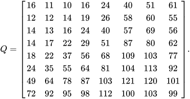
The quantized DCT coefficients are computed with

where is the unquantized DCT coefficients; is the quantization matrix above; and is the quantized DCT coefficients.


Using this quantization matrix with the DCT coefficient matrix from above results in:

![{\displaystyle B=\left[{\begin{array}{rrrrrrrr}-26&-3&-6&2&2&-1&0&0\\0&-2&-4&1&1&0&0&0\\-3&1&5&-1&-1&0&0&0\\-3&1&2&-1&0&0&0&0\\1&0&0&0&0&0&0&0\\0&0&0&0&0&0&0&0\\0&0&0&0&0&0&0&0\\0&0&0&0&0&0&0&0\end{array}}\right].}](https://wikimedia.org/api/rest_v1/media/math/render/svg/dfedb02fc67c95d021b46c13f4fb21c55a361671)
For example, using −415 (the DC coefficient) and rounding to the nearest integer

Notice that most of the higher-frequency elements of the sub-block (i.e., those with an x or y spatial frequency greater than 4) are quantized into zero values.
Entropy coding
[edit]
Entropy coding is a special form of lossless data compression. It involves arranging the image components in a "zigzag" order employing run-length encoding (RLE) algorithm that groups similar frequencies together, inserting length coding zeros, and then using Huffman coding on what is left.
The JPEG standard also allows, but does not require, decoders to support the use of arithmetic coding, which is mathematically superior to Huffman coding. However, this feature has rarely been used, as it was historically covered by patents requiring royalty-bearing licenses, and because it is slower to encode and decode compared to Huffman coding. Arithmetic coding typically makes files about 5–7% smaller.[58]
The previous quantized DC coefficient is used to predict the current quantized DC coefficient. The difference between the two is encoded rather than the actual value. The encoding of the 63 quantized AC coefficients does not use such prediction differencing.
The zigzag sequence for the above quantized coefficients are shown below. (The format shown is just for ease of understanding/viewing.)
−26 −3 0 −3 −2 −6 2 −4 1 −3 1 1 5 1 2 −1 1 −1 2 0 0 0 0 0 −1 −1 0 0 0 0 0 0 0 0 0 0 0 0 0 0 0 0 0 0 0 0 0 0 0 0 0 0 0 0 0 0 0 0 0 0 0 0 0 0
If the i-th block is represented by and positions within each block are represented by where and , then any coefficient in the DCT image can be represented as . Thus, in the above scheme, the order of encoding pixels (for the i-th block) is , , , , , , , and so on.






This encoding mode is called baseline sequential encoding. Baseline JPEG also supports progressive encoding. While sequential encoding encodes coefficients of a single block at a time (in a zigzag manner), progressive encoding encodes similar-positioned batch of coefficients of all blocks in one go (called a scan), followed by the next batch of coefficients of all blocks, and so on. For example, if the image is divided into N 8×8 blocks , then a 3-scan progressive encoding encodes DC component, for all blocks, i.e., for all , in first scan. This is followed by the second scan which encoding a few more components (assuming four more components, they are to , still in a zigzag manner) coefficients of all blocks (so the sequence is: ), followed by all the remained coefficients of all blocks in the last scan.



Once all similar-positioned coefficients have been encoded, the next position to be encoded is the one occurring next in the zigzag traversal as indicated in the figure above. It has been found that baseline progressive JPEG encoding usually gives better compression as compared to baseline sequential JPEG due to the ability to use different Huffman tables (see below) tailored for different frequencies on each "scan" or "pass" (which includes similar-positioned coefficients), though the difference is not too large.
In the rest of the article, it is assumed that the coefficient pattern generated is due to sequential mode.
In order to encode the above generated coefficient pattern, JPEG uses Huffman encoding. The JPEG standard provides general-purpose Huffman tables; encoders may also choose to generate Huffman tables optimized for the actual frequency distributions in images being encoded.
The process of encoding the zig-zag quantized data begins with a run-length encoding explained below, where:
- x is the non-zero, quantized AC coefficient.
- RUNLENGTH is the number of zeroes that came before this non-zero AC coefficient.
- SIZE is the number of bits required to represent x.
- AMPLITUDE is the bit-representation of x.
The run-length encoding works by examining each non-zero AC coefficient x and determining how many zeroes came before the previous AC coefficient. With this information, two symbols are created:
Symbol 1 Symbol 2 (RUNLENGTH, SIZE) (AMPLITUDE)
Both RUNLENGTH and SIZE rest on the same byte, meaning that each only contains four bits of information. The higher bits deal with the number of zeroes, while the lower bits denote the number of bits necessary to encode the value of x.
This has the immediate implication of Symbol 1 being only able store information regarding the first 15 zeroes preceding the non-zero AC coefficient. However, JPEG defines two special Huffman code words. One is for ending the sequence prematurely when the remaining coefficients are zero (called "End-of-Block" or "EOB"), and another when the run of zeroes goes beyond 15 before reaching a non-zero AC coefficient. In such a case where 16 zeroes are encountered before a given non-zero AC coefficient, Symbol 1 is encoded "specially" as: (15, 0)(0).
The overall process continues until "EOB" – denoted by (0, 0) – is reached.
With this in mind, the sequence from earlier becomes:
- (0, 2)(-3);(1, 2)(-3);(0, 2)(-2);(0, 3)(-6);(0, 2)(2);(0, 3)(-4);(0, 1)(1);(0, 2)(-3);(0, 1)(1);(0, 1)(1);
- (0, 3)(5);(0, 1)(1);(0, 2)(2);(0, 1)(-1);(0, 1)(1);(0, 1)(-1);(0, 2)(2);(5, 1)(-1);(0, 1)(-1);(0, 0);
(The first value in the matrix, −26, is the DC coefficient; it is not encoded the same way. See above.)
From here, frequency calculations are made based on occurrences of the coefficients. In our example block, most of the quantized coefficients are small numbers that are not preceded immediately by a zero coefficient. These more-frequent cases will be represented by shorter code words.
Compression ratio and artifacts
[edit]


The resulting compression ratio can be varied according to need by being more or less aggressive in the divisors used in the quantization phase. Ten to one compression usually results in an image that cannot be distinguished by eye from the original. A compression ratio of 100:1 is usually possible, but will look distinctly artifacted compared to the original. The appropriate level of compression depends on the use to which the image will be put.
| External image | |
|---|---|
 Illustration of edge busyness[59] Illustration of edge busyness[59] |
Those who use the World Wide Web may be familiar with the irregularities known as compression artifacts that appear in JPEG images, which may take the form of noise around contrasting edges (especially curves and corners), or "blocky" images. These are due to the quantization step of the JPEG algorithm. They are especially noticeable around sharp corners between contrasting colors (text is a good example, as it contains many such corners). The analogous artifacts in MPEG video are referred to as mosquito noise, as the resulting "edge busyness" and spurious dots, which change over time, resemble mosquitoes swarming around the object.[59][60]
These artifacts can be reduced by choosing a lower level of compression; they may be completely avoided by saving an image using a lossless file format, though this will result in a larger file size. The images created with ray-tracing programs have noticeable blocky shapes on the terrain. Certain low-intensity compression artifacts might be acceptable when simply viewing the images, but can be emphasized if the image is subsequently processed, usually resulting in unacceptable quality. Consider the example below, demonstrating the effect of lossy compression on an edge detection processing step.
| Image | Lossless compression | Lossy compression |
|---|---|---|
| Original |  |

|
| Processed by Canny edge detector |
 |

|
Some programs allow the user to vary the amount by which individual blocks are compressed. Stronger compression is applied to areas of the image that show fewer artifacts. This way it is possible to manually reduce JPEG file size with less loss of quality.
Since the quantization stage always results in a loss of information, JPEG standard is always a lossy compression codec. (Information is lost both in quantizing and rounding of the floating-point numbers.) Even if the quantization matrix is a matrix of ones, information will still be lost in the rounding step.
Decoding
[edit]Decoding to display the image consists of doing all the above in reverse.
Taking the DCT coefficient matrix (after adding the difference of the DC coefficient back in)
![{\displaystyle \left[{\begin{array}{rrrrrrrr}-26&-3&-6&2&2&-1&0&0\\0&-2&-4&1&1&0&0&0\\-3&1&5&-1&-1&0&0&0\\-3&1&2&-1&0&0&0&0\\1&0&0&0&0&0&0&0\\0&0&0&0&0&0&0&0\\0&0&0&0&0&0&0&0\\0&0&0&0&0&0&0&0\end{array}}\right]}](https://wikimedia.org/api/rest_v1/media/math/render/svg/d681176f165171c22d40b070b93cee3e7d627cc8)
and taking the entry-for-entry product with the quantization matrix from above results in
![{\displaystyle \left[{\begin{array}{rrrrrrrr}-416&-33&-60&32&48&-40&0&0\\0&-24&-56&19&26&0&0&0\\-42&13&80&-24&-40&0&0&0\\-42&17&44&-29&0&0&0&0\\18&0&0&0&0&0&0&0\\0&0&0&0&0&0&0&0\\0&0&0&0&0&0&0&0\\0&0&0&0&0&0&0&0\end{array}}\right]}](https://wikimedia.org/api/rest_v1/media/math/render/svg/d1336551027236825e4e96dad3e5da329b567f18)
which closely resembles the original DCT coefficient matrix for the top-left portion.
The next step is to take the two-dimensional inverse DCT (a 2D type-III DCT), which is given by:
![{\displaystyle f_{x,y}={\frac {1}{4}}\sum _{u=0}^{7}\sum _{v=0}^{7}\alpha (u)\alpha (v)F_{u,v}\cos \left[{\frac {(2x+1)u\pi }{16}}\right]\cos \left[{\frac {(2y+1)v\pi }{16}}\right]}](https://wikimedia.org/api/rest_v1/media/math/render/svg/b57a66586a29b5d371243341173f5fd1c00822b9)
where
- is the pixel row, for the integers .
- is the pixel column, for the integers .
- is the normalizing scale factor defined earlier, for the integers .
- is the approximated DCT coefficient at coordinates
- is the reconstructed pixel value at coordinates


Rounding the output to integer values (since the original had integer values) results in an image with values (still shifted down by 128)


![{\displaystyle \left[{\begin{array}{rrrrrrrr}-66&-63&-71&-68&-56&-65&-68&-46\\-71&-73&-72&-46&-20&-41&-66&-57\\-70&-78&-68&-17&20&-14&-61&-63\\-63&-73&-62&-8&27&-14&-60&-58\\-58&-65&-61&-27&-6&-40&-68&-50\\-57&-57&-64&-58&-48&-66&-72&-47\\-53&-46&-61&-74&-65&-63&-62&-45\\-47&-34&-53&-74&-60&-47&-47&-41\end{array}}\right]}](https://wikimedia.org/api/rest_v1/media/math/render/svg/3122f79ddeb024d01857afa1326287ef6ef8259e)
and adding 128 to each entry
![{\displaystyle \left[{\begin{array}{rrrrrrrr}62&65&57&60&72&63&60&82\\57&55&56&82&108&87&62&71\\58&50&60&111&148&114&67&65\\65&55&66&120&155&114&68&70\\70&63&67&101&122&88&60&78\\71&71&64&70&80&62&56&81\\75&82&67&54&63&65&66&83\\81&94&75&54&68&81&81&87\end{array}}\right].}](https://wikimedia.org/api/rest_v1/media/math/render/svg/97c63837bcedc3e999e024b101278c9ad8789553)
This is the decompressed subimage. In general, the decompression process may produce values outside the original input range of . If this occurs, the decoder needs to clip the output values so as to keep them within that range to prevent overflow when storing the decompressed image with the original bit depth.
The decompressed subimage can be compared to the original subimage (also see images to the right) by taking the difference (original − uncompressed) results in the following error values:
![{\displaystyle \left[{\begin{array}{rrrrrrrr}-10&-10&4&6&-2&-2&4&-9\\6&4&-1&8&1&-2&7&1\\4&9&8&2&-4&-10&-1&8\\-2&3&5&2&-1&-8&2&-1\\-3&-2&1&3&4&0&8&-8\\8&-6&-4&-0&-3&6&2&-6\\10&-11&-3&5&-8&-4&-1&-0\\6&-15&-6&14&-3&-5&-3&7\end{array}}\right]}](https://wikimedia.org/api/rest_v1/media/math/render/svg/57b41af069e9b6354156d2640bf40825c80b1b4a)
with an average absolute error of about 5 values per pixels (i.e., ).
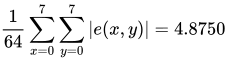
The error is most noticeable in the bottom-left corner where the bottom-left pixel becomes darker than the pixel to its immediate right.
Required precision
[edit]The required implementation precision of a JPEG codec is implicitly defined through the requirements formulated for compliance to the JPEG standard. These requirements are specified in ITU.T Recommendation T.83 | ISO/IEC 10918-2. Unlike MPEG standards and many later JPEG standards, the above document defines both required implementation precisions for the encoding and the decoding process of a JPEG codec by means of a maximal tolerable error of the forwards and inverse DCT in the DCT domain as determined by reference test streams. For example, the output of a decoder implementation must not exceed an error of one quantization unit in the DCT domain when applied to the reference testing codestreams provided as part of the above standard. While unusual, and unlike many other and more modern standards, ITU.T T.83 | ISO/IEC 10918-2 does not formulate error bounds in the image domain.
Effects of JPEG compression
[edit]JPEG compression artifacts blend well into photographs with detailed non-uniform textures, allowing higher compression ratios. Notice how a higher compression ratio first affects the high-frequency textures in the upper-left corner of the image, and how the contrasting lines become more fuzzy. The very high compression ratio severely affects the quality of the image, although the overall colors and image form are still recognizable. However, the precision of colors suffer less (for a human eye) than the precision of contours (based on luminance). This justifies the fact that images should be first transformed in a color model separating the luminance from the chromatic information, before subsampling the chromatic planes (which may also use lower quality quantization) in order to preserve the precision of the luminance plane with more information bits.
Sample photographs
[edit]
For information, the uncompressed 24-bit RGB bitmap image below (73,242 pixels) would require 219,726 bytes (excluding all other information headers). The filesizes indicated below include the internal JPEG information headers and some metadata. For highest quality images (Q=100), about 8.25 bits per color pixel is required. On grayscale images, a minimum of 6.5 bits per pixel is enough (a comparable Q=100 quality color information requires about 25% more encoded bits). The highest quality image below (Q=100) is encoded at nine bits per color pixel, the medium quality image (Q=25) uses one bit per color pixel. For most applications, the quality factor should not go below 0.75 bit per pixel (Q=12.5), as demonstrated by the low quality image. The image at lowest quality uses only 0.13 bit per pixel, and displays very poor color. This is useful when the image will be displayed in a significantly scaled-down size. A method for creating better quantization matrices for a given image quality using PSNR instead of the Q factor is described in Minguillón & Pujol (2001).[61]
Note: The above images are not IEEE / CCIR / EBU test images, and the encoder settings are not specified or available. Image Quality Size (bytes) Compression ratio Comment 
Highest quality (Q = 100) 81,447 2.7:1 Extremely minor artifacts 
High quality (Q = 50) 14,679 15:1 Initial signs of subimage artifacts 
Medium quality (Q = 25) 9,407 23:1 Stronger artifacts; loss of high frequency information 
Low quality (Q = 10) 4,787 46:1 Severe high frequency loss leads to obvious artifacts on subimage boundaries ("macroblocking") 
Lowest quality (Q = 1) 1,523 144:1 Extreme loss of color and detail; the leaves are nearly unrecognizable.


The medium quality photo uses only 4.3% of the storage space required for the uncompressed image, but has little noticeable loss of detail or visible artifacts. However, once a certain threshold of compression is passed, compressed images show increasingly visible defects. See the article on rate–distortion theory for a mathematical explanation of this threshold effect. A particular limitation of JPEG in this regard is its non-overlapped 8×8 block transform structure. More modern designs such as JPEG 2000 and JPEG XR exhibit a more graceful degradation of quality as the bit usage decreases – by using transforms with a larger spatial extent for the lower frequency coefficients and by using overlapping transform basis functions.
Lossless further compression
[edit]From 2004 to 2008, new research emerged on ways to further compress the data contained in JPEG images without modifying the represented image.[62][63][64][65] This has applications in scenarios where the original image is only available in JPEG format, and its size needs to be reduced for archiving or transmission. Standard general-purpose compression tools cannot significantly compress JPEG files.
Typically, such schemes take advantage of improvements to the naive scheme for coding DCT coefficients, which fails to take into account:
- Correlations between magnitudes of adjacent coefficients in the same block;
- Correlations between magnitudes of the same coefficient in adjacent blocks;
- Correlations between magnitudes of the same coefficient/block in different channels;
- The DC coefficients when taken together resemble a downscale version of the original image multiplied by a scaling factor. Well-known schemes for lossless coding of continuous-tone images can be applied, achieving somewhat better compression than the Huffman coded DPCM used in JPEG.
Some standard but rarely used options already exist in JPEG to improve the efficiency of coding DCT coefficients: the arithmetic coding option, and the progressive coding option (which produces lower bitrates because values for each coefficient are coded independently, and each coefficient has a significantly different distribution). Modern methods have improved on these techniques by reordering coefficients to group coefficients of larger magnitude together;[62] using adjacent coefficients and blocks to predict new coefficient values;[64] dividing blocks or coefficients up among a small number of independently coded models based on their statistics and adjacent values;[63][64] and most recently, by decoding blocks, predicting subsequent blocks in the spatial domain, and then encoding these to generate predictions for DCT coefficients.[65]
Typically, such methods can compress existing JPEG files between 15 and 25 percent, and for JPEGs compressed at low-quality settings, can produce improvements of up to 65%.[64][65]
A freely available tool called packJPG is based on the 2007 paper "Improved Redundancy Reduction for JPEG Files." As of version 2.5k of 2016, it reports a typical 20% reduction by transcoding.[66] JPEG XL (ISO/IEC 18181) of 2018 reports a similar reduction in its transcoding.
Derived formats for stereoscopic 3D
[edit]JPEG Stereoscopic
[edit]
JPS is a stereoscopic JPEG image used for creating 3D effects from 2D images. It contains two static images, one for the left eye and one for the right eye; encoded as two side-by-side images in a single JPEG file. JPEG Stereoscopic (JPS, extension .jps) is a JPEG-based format for stereoscopic images.[67][68] It has a range of configurations stored in the JPEG APP3 marker field, but usually contains one image of double width, representing two images of identical size in cross-eyed (i.e. left frame on the right half of the image and vice versa) side-by-side arrangement. This file format can be viewed as a JPEG without any special software, or can be processed for rendering in other modes.
JPEG Multi-Picture Format
[edit]| JPEG Multi-Picture | |
|---|---|
| Filename extension |
.mpo |
| Uniform Type Identifier (UTI) | public.mpo-image[69] |
JPEG Multi-Picture Format (MPO, extension .mpo) is a JPEG-based format for storing multiple images in a single file. It contains two or more JPEG files concatenated together.[70][71] It also defines a JPEG APP2 marker segment for image description. Various devices use it to store 3D images, such as Fujifilm FinePix Real 3D W1, HTC Evo 3D, JVC GY-HMZ1U AVCHD/MVC extension camcorder, Nintendo 3DS, Panasonic Lumix DMC-TZ20, DMC-TZ30, DMC-TZ60, DMC-TS4 (FT4), and Sony DSC-HX7V. Other devices use it to store "preview images" that can be displayed on a TV.
In the last few years, due to the growing use of stereoscopic images, much effort has been spent by the scientific community to develop algorithms for stereoscopic image compression.[72][73]
Implementations
[edit]A very important implementation of a JPEG codec is the free programming library libjpeg of the Independent JPEG Group. It was first published in 1991 and was key for the success of the standard. This library was used in countless applications.[3] The development went quiet in 1998; when libjpeg resurfaced with the 2009 version 7, it broke ABI compatibility with previous versions. Version 8 of 2010 introduced non-standard extensions, a decision criticized by the original IJG leader Tom Lane.[74]
libjpeg-turbo, forked from the 1998 libjpeg 6b, improves on libjpeg with SIMD optimizations. Originally seen as a maintained fork of libjpeg, it has become more popular after the incompatible changes of 2009.[75][76] In 2019, it became the ITU|ISO/IEC reference implementation as ISO/IEC 10918-7 and ITU-T T.873.[77]
ISO/IEC Joint Photographic Experts Group maintains the other reference software implementation under the JPEG XT heading. It can encode both base JPEG (ISO/IEC 10918-1 and 18477–1) and JPEG XT extensions (ISO/IEC 18477 Parts 2 and 6–9), as well as JPEG-LS (ISO/IEC 14495).[78] In 2016, "JPEG on steroids" was introduced as an option for the ISO JPEG XT reference implementation.[79]
There is persistent interest in encoding JPEG in unconventional ways that maximize image quality for a given file size. In 2014, Mozilla created MozJPEG from libjpeg-turbo, a slower but higher-quality encoder intended for web images.[80] In March 2017, Google released the open source project Guetzli, which trades off a much longer encoding time for smaller file size (similar to what Zopfli does for PNG and other lossless data formats).[81]
In April 2024, Google introduced Jpegli, a new JPEG coding library that offers enhanced capabilities and a 35% compression ratio improvement at high quality compression settings, while the coding speed is comparable with MozJPEG.[82]
Successors
[edit]The Joint Photographic Experts Group has developed several newer standards meant to complement or replace the functionality of the original JPEG format.
JPEG LS
[edit]Originating in 1993 and published as ISO-14495-1/ITU-T.87, JPEG LS offers a low-complexity lossless file format which was more efficient than JPEG's original lossless implementation. It also features a lossy mode close to lossless. Its functionality is largely limited to that, and largely shares the same limitations of the original JPEG in other aspects.
JPEG 2000
[edit]JPEG 2000 was published as ISO/IEC 15444 in December 2000. It is based on a discrete wavelet transform (DWT) and was designed to completely replace the original JPEG standard and exceed it in every way. It allows up to 38 bits per colour channel and 16384 channels, more than any other format, with a multitude of colour spaces, and thus high dynamic range (HDR). Furthermore, it supports alpha transparency coding, billions-by-billions pixel images, which is also more than any other format, and lossless compression. It has significantly improved lossy compression ratio with significantly less visible artefacts at strong compression levels.[83]
JPEG XT
[edit]JPEG XT (ISO/IEC 18477) was published in June 2015; it extends base JPEG format with support for higher integer bit depths (up to 16 bit), high dynamic range imaging and floating-point coding, lossless coding, and alpha channel coding. Extensions are backward compatible with the base JPEG/JFIF file format and 8-bit lossy compressed image. JPEG XT uses an extensible file format based on JFIF. Extension layers are used to modify the JPEG 8-bit base layer and restore the high-resolution image. Existing software is forward compatible and can read the JPEG XT binary stream, though it would only decode the base 8-bit layer.[84]
JPEG XL
[edit]JPEG XL (ISO/IEC 18181) was published in 2021–2022. It replaces the JPEG format with a new DCT-based royalty-free format and allows efficient transcoding as a storage option for traditional JPEG images.[85] The new format is designed to exceed the still image compression performance shown by HEIF HM, Daala and WebP. It supports billion-by-billion pixel images, up to 32-bit-per-component high dynamic range with the appropriate transfer functions (PQ and HLG), patch encoding of synthetic images such as bitmap fonts and gradients, animated images, alpha channel coding, and a choice of RGB/YCbCr/ICtCp color encoding.[86][87][88][89]
See also
[edit]- AVIF
- Better Portable Graphics, a format based on intra-frame encoding of the HEVC
- C-Cube, an early implementer of JPEG in chip form
- Comparison of graphics file formats
- Deblocking filter (video), the similar deblocking methods could be applied to JPEG
- Design rule for Camera File system (DCF)
- FELICS, a lossless image codec
- File extensions
- Graphics editing program
- High Efficiency Image File Format, image container format for HEVC and other image coding formats
- Lenna (test image), the traditional standard image used to test image processing algorithms
- Motion JPEG
- WebP
References
[edit]- ^ a b c d e "T.81 – DIGITAL COMPRESSION AND CODING OF CONTINUOUS-TONE STILL IMAGES – REQUIREMENTS AND GUIDELINES" (PDF). CCITT. September 1992. Archived (PDF) from the original on 30 December 2019. Retrieved 12 July 2019.
- ^ "Definition of "JPEG"". Collins English Dictionary. Archived from the original on 21 September 2013. Retrieved 23 May 2013.
- ^ a b "Overview of JPEG 1". Joint Photographic Experts Group. Archived from the original on 30 January 2025. Retrieved 5 February 2025.
- ^ Haines, Richard F.; Chuang, Sherry L. (1 July 1992). The effects of video compression on acceptability of images for monitoring life sciences experiments (Technical report). NASA. NASA-TP-3239, A-92040, NAS 1.60:3239. Retrieved 13 March 2016.
The JPEG still-image-compression levels, even with the large range of 5:1 to 120:1 in this study, yielded equally high levels of acceptability
- ^ a b Hudson, Graham; Léger, Alain; Niss, Birger; Sebestyén, István; Vaaben, Jørgen (31 August 2018). "JPEG-1 standard 25 years: past, present, and future reasons for a success". Journal of Electronic Imaging. 27 (4): 1. doi:10.1117/1.JEI.27.4.040901. S2CID 52164892.
- ^ Svetlik, Joe (31 May 2018). "The JPEG Image Format Explained". BT.com. BT Group. Archived from the original on 5 August 2019. Retrieved 5 August 2019.
- ^ Baraniuk, Chris (15 October 2015). "Copy Protections Could Come to JPEGs". BBC News. BBC. Archived from the original on 9 October 2019. Retrieved 13 September 2019.
- ^ Trinkwalder, Andrea (7 October 2016). "JPEG: 25 Jahre und kein bisschen alt" [JPEG: 25 years (old) and not a bit old]. de:Heise online (in German). Archived from the original on 5 September 2019. Retrieved 5 September 2019.
- ^ a b c "T.81 – DIGITAL COMPRESSION AND CODING OF CONTINUOUS-TONE STILL IMAGES – REQUIREMENTS AND GUIDELINES" (PDF). CCITT. September 1992. Retrieved 12 July 2019.
- ^ a b c "JPEG: 25 Jahre und kein bisschen alt". Heise online (in German). October 2016. Retrieved 5 September 2019.
- ^ Caplan, Paul (24 September 2013). "What Is a JPEG? The Invisible Object You See Every Day". The Atlantic. Archived from the original on 9 October 2019. Retrieved 13 September 2019.
- ^ "HTTP Archive – Interesting Stats". httparchive.org. Retrieved 6 April 2016.
- ^ "MIME Type Detection in Internet Explorer". Microsoft. 13 July 2016. Archived from the original on 30 October 2022. Retrieved 2 November 2022.
- ^ "JPEG File Interchange Format" (PDF). 3 September 2014. Archived from the original on 3 September 2014. Retrieved 16 October 2017.
{{cite web}}: CS1 maint: bot: original URL status unknown (link) - ^ "Why JPEG 2000 Never Took Off". American National Standards Institute. 10 July 2018. Archived from the original on 16 December 2018. Retrieved 13 September 2019.
- ^ Ahmed, Nasir (January 1991). "How I Came Up With the Discrete Cosine Transform". Digital Signal Processing. 1 (1): 4–5. Bibcode:1991DSP.....1....4A. doi:10.1016/1051-2004(91)90086-Z.
- ^ Ahmed, Nasir; Natarajan, T.; Rao, K. R. (January 1974), "Discrete Cosine Transform", IEEE Transactions on Computers, C-23 (1): 90–93, doi:10.1109/T-C.1974.223784, S2CID 149806273
- ^ a b c d Lemos, Robert (23 July 2002). "Finding patent truth in JPEG claim". CNET. Archived from the original on 13 July 2019. Retrieved 13 July 2019.
- ^ ISO/IEC JTC 1/SC 29 (7 May 2009). "ISO/IEC JTC 1/SC 29/WG 1 – Coding of Still Pictures (SC 29/WG 1 Structure)". Archived from the original on 31 December 2013. Retrieved 11 November 2009.
{{cite web}}: CS1 maint: numeric names: authors list (link) - ^ a b ISO/IEC JTC 1/SC 29. "Programme of Work, (Allocated to SC 29/WG 1)". Archived from the original on 31 December 2013. Retrieved 7 November 2009.
{{cite web}}: CS1 maint: numeric names: authors list (link) - ^ ISO. "JTC 1/SC 29 – Coding of audio, picture, multimedia and hypermedia information". Archived from the original on 3 July 2010. Retrieved 11 November 2009.
- ^ a b JPEG. "Joint Photographic Experts Group, JPEG Homepage". Archived from the original on 27 September 2009. Retrieved 8 November 2009.
- ^ "T.81: Information technology – Digital compression and coding of continuous-tone still images – Requirements and guidelines". Itu.int. Archived from the original on 6 November 2012. Retrieved 7 November 2009.
- ^ William B. Pennebaker; Joan L. Mitchell (1993). JPEG still image data compression standard (3rd ed.). Springer. p. 291. ISBN 978-0-442-01272-4.
- ^ ISO. "JTC 1/SC 29 – Coding of audio, picture, multimedia and hypermedia information". Archived from the original on 3 July 2010. Retrieved 7 November 2009.
- ^ "SPIFF, Still Picture Interchange File Format". Library of Congress. 30 January 2012. Archived from the original on 31 July 2018. Retrieved 31 July 2018.
- ^ Louis Sharpe (24 April 2009). "JPEG XR enters FDIS status JPEG File Interchange Format (JFIF) to be standardized as JPEG Part 5" (Press release). Archived from the original on 8 October 2009. Retrieved 9 November 2009.
- ^ "JPEG File Interchange Format (JFIF)". ECMA TR/98 1st ed. Ecma International. 2009. Archived from the original on 14 January 2021. Retrieved 1 August 2011.
- ^ "Forgent's JPEG Patent". SourceForge. 2002. Archived from the original on 13 May 2019. Retrieved 13 July 2019.
- ^ "Concerning recent patent claims". Jpeg.org. 19 July 2002. Archived from the original on 14 July 2007. Retrieved 29 May 2011.
- ^ "JPEG and JPEG2000 – Between Patent Quarrel and Change of Technology". Archived from the original on 17 August 2004. Retrieved 16 April 2017.
{{cite web}}: CS1 maint: bot: original URL status unknown (link) - ^ Kawamoto, Dawn (22 April 2005). "Graphics patent suit fires back at Microsoft". CNET News. Archived from the original on 20 January 2023. Retrieved 20 January 2023.
- ^ "Trademark Office Re-examines Forgent JPEG Patent". Publish.com. 3 February 2006. Archived from the original on 15 May 2016. Retrieved 28 January 2009.
- ^ "USPTO: Broadest Claims Forgent Asserts Against JPEG Standard Invalid". Groklaw.net. 26 May 2006. Archived from the original on 16 May 2019. Retrieved 21 July 2007.
- ^ "Coding System for Reducing Redundancy". Gauss.ffii.org. Archived from the original on 12 June 2011. Retrieved 29 May 2011.
- ^ "JPEG Patent Claim Surrendered". Public Patent Foundation. 2 November 2006. Archived from the original on 2 January 2007. Retrieved 3 November 2006.
- ^ "Ex Parte Reexamination Certificate for U.S. Patent No. 5,253,341". Archived from the original on 2 June 2008.
- ^ Workgroup. "Rozmanith: Using Software Patents to Silence Critics". Eupat.ffii.org. Archived from the original on 16 July 2011. Retrieved 29 May 2011.
- ^ "A Bounty of $5,000 to Name Troll Tracker: Ray Niro Wants To Know Who Is saying All Those Nasty Things About Him". Law.com. Archived from the original on 21 November 2010. Retrieved 29 May 2011.
- ^ Reimer, Jeremy (5 February 2008). "Hunting trolls: USPTO asked to reexamine broad image patent". Arstechnica.com. Archived from the original on 8 December 2008. Retrieved 29 May 2011.
- ^ U.S. Patent Office – Granting Reexamination on 5,253,341 C1
- ^ "Judge Puts JPEG Patent On Ice". Techdirt.com. 30 April 2008. Archived from the original on 14 November 2011. Retrieved 29 May 2011.
- ^ "JPEG Patent's Single Claim Rejected (And Smacked Down For Good Measure)". Techdirt.com. 1 August 2008. Archived from the original on 28 November 2019. Retrieved 29 May 2011.
- ^ Workgroup. "Princeton Digital Image Corporation Home Page". Archived from the original on 11 April 2013. Retrieved 1 May 2013.
- ^ Workgroup (3 April 2013). "Article on Princeton Court Ruling Regarding GE License Agreement". Archived from the original on 9 March 2016. Retrieved 1 May 2013.
- ^ a b Kaur, Rajandeep (May 2016). "A Review of Image Compression Techniques". International Journal of Computer Applications. 142 (1): 8–11. doi:10.5120/ijca2016909658.
- ^ "Progressive Decoding Overview". Microsoft Developer Network. Microsoft. Archived from the original on 19 November 2012. Retrieved 23 March 2012.
- ^ Fastvideo (May 2019). "12-bit JPEG encoder on GPU". Archived from the original on 6 May 2019. Retrieved 6 May 2019.
- ^ "Why You Should Always Rotate Original JPEG Photos Losslessly". Petapixel.com. 14 August 2012. Archived from the original on 17 October 2017. Retrieved 16 October 2017.
- ^ "JFIF File Format as PDF" (PDF). Archived (PDF) from the original on 13 January 2021. Retrieved 19 June 2006.
- ^ Tom Lane (29 March 1999). "JPEG image compression FAQ". Archived from the original on 10 November 2010. Retrieved 11 September 2007. (q. 14: "Why all the argument about file formats?")
- ^ "Everything you need to know about JPEG files | Adobe". www.adobe.com. Retrieved 18 August 2023.
- ^ a b "A Standard Default Color Space for the Internet - sRGB". www.w3.org. Archived from the original on 18 February 2022. Retrieved 18 February 2022.
- ^ a b "IEC 61966-2-1:1999/AMD1:2003 | IEC Webstore". webstore.iec.ch. Archived from the original on 18 February 2022. Retrieved 18 February 2022.
- ^ "ISO/IEC 10918-1: 1993(E) p.36". Archived from the original on 1 August 2011. Retrieved 30 November 2007.
- ^ Thomas G. Lane. "Advanced Features: Compression parameter selection". Using the IJG JPEG Library. Archived from the original on 26 November 2001. Retrieved 8 October 2008.
- ^ "DC / AC Frequency Questions - Doom9's Forum". forum.doom9.org. Archived from the original on 17 October 2017. Retrieved 16 October 2017.
- ^ Maini, Raman; Mehra, Suruchi (December 2010). "A Review on JPEG2000 Image Compression". International Journal of Computer Applications. 11 (9): 43–47. doi:10.5120/1607-2159 – via CiteSeerX.
- ^ a b Phuc-Tue Le Dinh and Jacques Patry. Video compression artifacts and MPEG noise reduction Archived 2006-03-14 at the Wayback Machine. Video Imaging DesignLine. 24 February 2006. Retrieved 28 May 2009.
- ^ "3.9 mosquito noise: Form of edge busyness distortion sometimes associated with movement, characterized by moving artifacts and/or blotchy noise patterns superimposed over the objects (resembling a mosquito flying around a person's head and shoulders)." ITU-T Rec. P.930 (08/96) Principles of a reference impairment system for video Archived 2010-02-16 at the Wayback Machine
- ^ Julià Minguillón, Jaume Pujol (April 2001). "JPEG standard uniform quantization error modeling with applications to sequential and progressive operation modes" (PDF). Electronic Imaging. 10 (2): 475–485. Bibcode:2001JEI....10..475M. doi:10.1117/1.1344592. hdl:10609/6263. S2CID 16629522. Archived (PDF) from the original on 3 August 2020. Retrieved 23 September 2019.
- ^ a b I. Bauermann and E. Steinbacj. Further Lossless Compression of JPEG Images. Proc. of Picture Coding Symposium (PCS 2004), San Francisco, US, 15–17 December 2004.
- ^ a b N. Ponomarenko, K. Egiazarian, V. Lukin and J. Astola. Additional Lossless Compression of JPEG Images, Proc. of the 4th Intl. Symposium on Image and Signal Processing and Analysis (ISPA 2005), Zagreb, Croatia, pp. 117–120, 15–17 September 2005.
- ^ a b c d M. Stirner and G. Seelmann. Improved Redundancy Reduction for JPEG Files. Proc. of Picture Coding Symposium (PCS 2007), Lisbon, Portugal, 7–9 November 2007
- ^ a b c Ichiro Matsuda, Yukio Nomoto, Kei Wakabayashi and Susumu Itoh. Lossless Re-encoding of JPEG images using block-adaptive intra prediction. Proceedings of the 16th European Signal Processing Conference (EUSIPCO 2008).
- ^ Stirner, Matthias (19 February 2023). "packjpg/packJPG". GitHub. Archived from the original on 2 March 2023. Retrieved 2 March 2023.
- ^ J. Siragusa; D. C. Swift (1997). "General Purpose Stereoscopic Data Descriptor" (PDF). VRex, Inc., Elmsford, New York, US. Archived from the original (PDF) on 30 October 2011.
- ^ Tim Kemp, JPS files Archived 2009-01-18 at the Wayback Machine
- ^ "CGImageSource.SupportedTypes". Claris FileMaker MBS Plug-in. MonkeyBread Software. Archived from the original on 30 December 2020. Retrieved 21 May 2023.
- ^ "Multi-Picture Format" (PDF). 2009. Archived from the original (PDF) on 5 April 2016. Retrieved 30 December 2015.
- ^ "MPO2Stereo: Convert Fujifilm MPO files to JPEG stereo pairs", Mtbs3d.com, archived from the original on 31 May 2010, retrieved 12 January 2010
- ^ Alessandro Ortis; Sebastiano Battiato (2015), Sitnik, Robert; Puech, William (eds.), "A new fast matching method for adaptive compression of stereoscopic images", Three-Dimensional Image Processing, Three-Dimensional Image Processing, Measurement (3DIPM), and Applications 2015, 9393, SPIE - Three-Dimensional Image Processing, Measurement (3DIPM), and Applications 2015: 93930K, Bibcode:2015SPIE.9393E..0KO, doi:10.1117/12.2086372, S2CID 18879942, archived from the original on 3 March 2016, retrieved 30 April 2015
- ^ Alessandro Ortis; Francesco Rundo; Giuseppe Di Giore; Sebastiano Battiato, Adaptive Compression of Stereoscopic Images, International Conference on Image Analysis and Processing (ICIAP) 2013, archived from the original on 3 March 2016, retrieved 30 April 2015
- ^ Tom Lane, 16 January 2013: jpeg-9, API/ABI compatibility, and the future role of this project Archived 2018-12-04 at the Wayback Machine
- ^ Software That Uses or Provides libjpeg-turbo Archived 2017-03-18 at the Wayback Machine. 9 February 2012.
- ^ Issue 48789 – chromium – Use libjpeg-turbo instead of libjpeg Archived 2015-08-01 at the Wayback Machine. 14 April 2011.
- ^ "ISO/IEC 10918-7: 2023 Information technology — Digital compression and coding of continuous-tone still images — Part 7: Reference software". ISO. Retrieved 24 June 2025."T.873 (05/19): Information technology - Digital compression and coding of continuous-tone still images: Reference software". www.itu.int. Archived from the original on 2 June 2022. Retrieved 1 March 2023.
- ^ "JPEG - JPEG XT". jpeg.org. Archived from the original on 4 March 2018. Retrieved 3 March 2018.
- ^ Richter, Thomas (September 2016). "JPEG on STEROIDS: Common optimization techniques for JPEG image compression". 2016 IEEE International Conference on Image Processing (ICIP). pp. 61–65. doi:10.1109/ICIP.2016.7532319. ISBN 978-1-4673-9961-6. S2CID 14922251.
- ^ "Introducing the 'mozjpeg' Project". Mozilla Research. 5 March 2014. Archived from the original on 1 March 2023. Retrieved 1 March 2023.
- ^ "Announcing Guetzli: A New Open Source JPEG Encoder". Research.googleblog.com. 16 March 2017. Archived from the original on 6 October 2017. Retrieved 16 October 2017.
- ^ "Introducing Jpegli: A New JPEG Coding Library". Google Open Source Blog. 3 April 2024. Archived from the original on 3 April 2024. Retrieved 4 April 2024.
- ^ Sneyers, Jon (22 February 2021). "It's High Time to Replace JPEG With a Next-Generation Image Codec". Cloudinary. Retrieved 14 November 2023.
- ^ "JPEG - JPEG XT". jpeg.org. Archived from the original on 4 March 2018. Retrieved 3 March 2018.
- ^ Alakuijala, Jyrki; van Asseldonk, Ruud; Boukortt, Sami; Bruse, Martin; Comșa, Iulia-Maria; Firsching, Moritz; Fischbacher, Thomas; Kliuchnikov, Evgenii; Gomez, Sebastian; Obryk, Robert; Potempa, Krzysztof; Rhatushnyak, Alexander; Sneyers, Jon; Szabadka, Zoltan; Vandervenne, Lode; Versari, Luca; Wassenberg, Jan (6 September 2019). "JPEG XL next-generation image compression architecture and coding tools". In Tescher, Andrew G; Ebrahimi, Touradj (eds.). Applications of Digital Image Processing XLII. Vol. 11137. p. 20. Bibcode:2019SPIE11137E..0KA. doi:10.1117/12.2529237. ISBN 978-1-5106-2967-7. S2CID 202785129. Archived from the original on 26 December 2021. Retrieved 26 December 2021.
- ^ Rhatushnyak, Alexander; Wassenberg, Jan; Sneyers, Jon; Alakuijala, Jyrki; Vandevenne, Lode; Versari, Luca; Obryk, Robert; Szabadka, Zoltan; Kliuchnikov, Evgenii; Comsa, Iulia-Maria; Potempa, Krzysztof; Bruse, Martin; Firsching, Moritz; Khasanova, Renata; Ruud van Asseldonk; Boukortt, Sami; Gomez, Sebastian; Fischbacher, Thomas (2019). "Committee Draft of JPEG XL Image Coding System". arXiv:1908.03565 [eess.IV].
- ^ "N79010 Final Call for Proposals for a Next-Generation Image Coding Standard (JPEG XL)" (PDF). ISO/IEC JTC 1/SC 29/WG 1 (ITU-T SG16). Archived (PDF) from the original on 31 October 2022. Retrieved 29 May 2018.
- ^ ISO/IEC 18181-1:2022 Information technology — JPEG XL image coding system — Part 1: Core coding system.
- ^ ISO/IEC 18181-2:2021 Information technology — JPEG XL image coding system — Part 2: File format.
External links
[edit]
- Official website

- JPEG Standard (JPEG ISO/IEC 10918-1 ITU-T Recommendation T.81) at W3.org
- JPEG File Interchange Format (JFIF), Version 1.02, Sept. 1992 at W3.org
- Format description of JPEG Image Coding Family from Library of Congress
- Example images over the full range of quantization levels from 1 to 100 at visengi.com
| Raster |
|
|---|---|
| Raw | |
| Vector | |
| Compound | |
| Metadata |
|


History
Background and Development
The development of JPEG originated from foundational research in image compression techniques during the 1970s, driven by the growing need to handle large volumes of digital image data efficiently as computing and storage technologies advanced. A pivotal contribution came from Nasir Ahmed, who, along with T. Natarajan and K. R. Rao, introduced the discrete cosine transform (DCT) in 1974 as a method for transform coding of images. This technique concentrated image energy into fewer coefficients, enabling effective compression by discarding less perceptually important high-frequency components, and laid the groundwork for subsequent standards in digital photography and visual data transmission. By the late 1970s and early 1980s, the proliferation of digital imaging in applications such as medical imaging, satellite photography, and early desktop publishing highlighted the limitations of uncompressed formats, which required substantial storage and bandwidth—often millions of bytes per color image. This spurred interest in standardized compression for continuous-tone color images, influenced by prior successes in bilevel image transmission, including the CCITT Group 3 analog fax standard developed for efficient document scanning over telephone lines. In response, the Joint Photographic Experts Group (JPEG) was formally established in 1986 as a collaborative committee under the International Organization for Standardization/International Electrotechnical Commission (ISO/IEC) JTC 1 and the ITU Telecommunication Standardization Sector (ITU-T, formerly CCITT), aiming to create a versatile standard for photographic image encoding.[2][4] Key figures in the group's early efforts included Gregory K. Wallace, who served as chair starting in 1988 and authored influential overviews of the emerging standard, guiding its technical direction toward practical implementation. The initial objectives focused on achieving compression ratios of 10:1 to 20:1 for typical color images, balancing significant data reduction with minimal visible quality degradation to support emerging uses in digital storage, telecommunications, and multimedia systems.[2]Standardization Process
The Joint Photographic Experts Group (JPEG) held its inaugural meeting in November 1986 in Parsippany, New Jersey, USA, marking the formal start of collaborative efforts to develop a standardized image compression method.[8] Subsequent meetings in 1987, including one in March at Darmstadt, Germany, focused on registering candidate compression techniques, while a June session in Copenhagen evaluated and narrowed proposals to three primary options.[8] In January 1988, during a second testing meeting in Copenhagen, the group selected the Adaptive Discrete Cosine Transform (ADCT) technique as the basis for the standard, leading to the development of an initial draft proposal later that year.[8] Iterative refinements continued through meetings in 1989 and 1990, culminating in the approval of ISO Committee Draft (CD) 10918 in April 1990 and its submission for ballot in February 1991.[8] The Draft International Standard (DIS) ballot began in January 1992, with accelerated approval by the International Telegraph and Telephone Consultative Committee (CCITT) on September 18, 1992, as Recommendation T.81, and final ISO publication of Part 1 (ISO/IEC 10918-1) in February 1994.[8][1] The JPEG standard is structured into multiple parts under ISO/IEC 10918, with Part 1 defining the core encoding and decoding processes for lossy and lossless compression of continuous-tone still images, including baseline sequential and progressive modes.[4][1] Part 2, published in 1995, establishes procedures for compliance testing of encoders and decoders. Part 3, from 1997, extends the core with features like hierarchical coding and the SPIFF file format, while Part 4 handles registration of profiles and color spaces.[4] Later additions include Part 5 (2013) for the JPEG File Interchange Format (JFIF) and Part 6 (2013) for printing applications.[4] To address practical file handling beyond the core bitstream defined in Part 1, JFIF was developed in late 1991 under the leadership of Eric Hamilton and agreed upon at a C-Cube meeting, with version 1.02 published on September 1, 1992.[8] This format encapsulates JPEG-compressed data with metadata for interchange, and it was later formalized as ISO/IEC 10918-5 in 2013.Patent and Legal Controversies
The development of the JPEG standard in the early 1990s was intended to be royalty-free, with participants declaring no essential patents during the ISO/IEC standardization process. However, post-standardization, several companies asserted patent claims on technologies incorporated into JPEG implementations, leading to significant legal disputes and licensing requirements that affected widespread adoption.[9] A prominent controversy centered on U.S. Patent No. 4,698,672, originally held by Compression Labs, Inc. (CLI), which described a coding system for reducing redundancy in digital signals through techniques including the Discrete Cosine Transform (DCT) for image and video compression. Issued on October 6, 1987, the patent was acquired by Forgent Networks in 1997 following its purchase of CLI. Starting in 2002, Forgent aggressively enforced the patent, claiming it covered essential elements of the JPEG compression algorithm, and initiated licensing programs and lawsuits against numerous technology companies, including major players in digital imaging and consumer electronics. By 2004, Forgent had sued over 30 companies for alleged infringement and secured settlements or licenses from at least 13, generating more than $105 million in revenue primarily from these efforts.[10][11][12] These actions drew widespread criticism, with Forgent labeled a "patent troll" for its business model focused on litigation rather than innovation, prompting concerns over retroactive royalties that could burden the open implementation of JPEG in software and hardware. The U.S. Patent and Trademark Office re-examined the patent's validity in 2006 amid challenges, but enforcement continued until its expiration. The patent's 20-year term from filing ended on October 27, 2006, after which Forgent abandoned further claims in November 2006, settling ongoing cases for $8 million with a coalition of defendants.[12][13][14] Subsequent disputes involved other asserted patents, such as U.S. Patent No. 5,253,341 claimed by Global Patent Holdings in 2007 to cover aspects of JPEG decoding, leading to additional lawsuits against image-processing firms. No formal patent pool like those for MPEG video standards was established for baseline JPEG; instead, individual assertions created fragmented licensing landscapes until the mid-2010s. By around 2009–2010, all major claimed patents essential to the original JPEG standard had expired, rendering the format fully royalty-free and facilitating its unchallenged ubiquity in digital imaging.[15][9]Overview and Applications
Core Principles
JPEG, formally known as the Joint Photographic Experts Group standard, is a family of international standards defined under ISO/IEC 10918 for the compression of continuous-tone still images, such as grayscale and color photographs.[1][4] Developed to enable efficient storage and transmission of digital images across diverse applications, it provides a flexible framework for encoding and decoding image data while balancing file size and visual quality.[16] The core coding processes outlined in ISO/IEC 10918-1 specify methods for converting source image data into compressed representations and reconstructing images from those streams, supporting both lossy and lossless variants to accommodate varying requirements.[1] At its foundation, JPEG employs lossy compression techniques that irreversibly discard less perceptually significant data to achieve substantial reductions in file size, exploiting properties of the human visual system to minimize noticeable artifacts.[17] This approach prioritizes data that contributes most to perceived image quality, such as low-frequency components, while approximating or eliminating high-frequency details that are less critical for natural scenes.[16] Unlike lossless methods, which preserve all original data exactly, JPEG's lossy mode introduces controlled approximations, making it particularly suitable for photographic content where exact reproduction is secondary to efficiency.[17] The standard encompasses several operational modes to support different use cases and decoding capabilities. The baseline mode uses sequential discrete cosine transform (DCT)-based encoding with Huffman coding for 8-bit samples per component, providing a straightforward, widely compatible implementation for typical color images.[16] Extended modes build on this by incorporating options for 12-bit samples, arithmetic coding, and spectral selection, enabling higher precision and alternative entropy encoding.[16] Progressive modes, in contrast, organize the encoded data into multiple scans—either by spectral selection or successive approximation—allowing images to be decoded in passes from low to high resolution, which is advantageous for progressive display over slow connections.[16] Additionally, a lossless mode is included for applications requiring exact data fidelity, though it has been largely supplanted by later standards like JPEG-LS.[17] Compression ratios in JPEG typically range from 10:1 to 20:1 for lossy modes, meaning files can be reduced to 5-10% of their uncompressed size with acceptable visual quality. For instance, a typical 800×600 photographic image compresses from an uncompressed 1.44 MB to approximately 50–150 KB at quality levels of 80–90%, demonstrating practical application of the adjustable trade-off between file size and fidelity. Though higher ratios up to 50:1 are possible at the cost of increased artifacts.[17][16] These ratios are adjustable through user-defined quality parameters that control the extent of data discard, allowing trade-offs between file size and fidelity tailored to specific needs, such as web display or archival storage.[16]Typical Uses and Adoption
JPEG serves as the primary image format for digital photography and online visuals, widely employed in digital cameras and smartphones for capturing and storing photographs. It is the default output for most consumer imaging devices, enabling efficient handling of high-resolution images with support for up to 16 million colors. On the web, JPEG files, commonly identified by the .jpg extension, dominate photographic content, powering the majority of images shared across websites, social media, and email attachments.[18][6][19] Since its introduction in the early 1990s, JPEG has seen massive adoption, establishing itself as the cornerstone of digital imaging due to its balance of quality and efficiency. By 2025, it is utilized by 73.6% of all websites, underscoring its enduring dominance in web imagery despite the emergence of alternatives like WebP. This widespread use stems from its role in reducing bandwidth demands during the internet's expansion, making it essential for everything from personal photo sharing to commercial e-commerce visuals.[7][5] The format's key advantages include dramatically smaller file sizes through lossy compression—often achieving 10:1 reduction without noticeable quality loss for photographs—which optimizes storage and accelerates transmission over networks. Its universal compatibility across operating systems, browsers, and hardware devices further cements its practicality for everyday applications. However, JPEG is less suitable for graphics or text-heavy images, where lossy compression can introduce artifacts around edges, making lossless formats like PNG or GIF preferable for logos, diagrams, or illustrations. In professional printing, it is typically avoided due to quality loss during scaling or recompression, with vector or high-fidelity raster formats favored instead for sharp, reproducible results.[20][21][22]File Formats and Compatibility
Filename Extensions and Containers
JPEG files are commonly identified by the filename extensions .jpg, .jpeg, .jpe, .jif, .jfif, and .jfi.[6] Notably, .jpg and .jpeg refer to the exact same image file format developed by the Joint Photographic Experts Group; the only difference is the extension length, with .jpg using three characters due to historical limitations in older Windows and MS-DOS systems that restricted file extensions to three characters, while .jpeg uses four. Files with either extension are fully interchangeable and contain identical data.[6] These extensions help operating systems and applications recognize and handle JPEG images appropriately.[23] Regional or legacy variations, such as .jif, may appear in certain contexts or older systems.[6] The most prevalent container format for JPEG data is the JPEG File Interchange Format (JFIF), introduced in 1992.[24] JFIF provides a minimal structure for embedding JPEG bitstreams, including basic metadata such as image resolution via the APP0 marker segment.[24] This format ensures interoperability across diverse platforms and applications by standardizing the file wrapper around the compressed image data.[24] Another common container is the Exchangeable Image File Format (Exif), widely used in digital photography to store camera-specific metadata like date, time, exposure settings, and GPS location within JPEG files.[6] Exif extends JFIF by incorporating additional application segments for richer descriptive information.[6] The Still Picture Interchange File Format (SPIFF), defined in ISO/IEC 10918-3 from 1997, serves as an alternative container supporting both lossy and lossless JPEG compression, though it sees limited adoption compared to JFIF and Exif.[25] SPIFF was designed for broader still image interchange but has not gained widespread use.[26] Compatibility considerations include case sensitivity of extensions on certain file systems, such as Linux servers, where .JPG and .jpg may be treated as distinct files, potentially causing issues in mixed environments.[27] The standard MIME type for JPEG files is image/jpeg, ensuring consistent web transmission and rendering across browsers.[23]Color Management and Profiles
JPEG images do not inherently specify a color space within the core standard, allowing flexibility in encoding, but the widely adopted JPEG File Interchange Format (JFIF) specifies YCbCr as the standard color space for color images, with 256 levels per component as defined by ITU-R BT.601.[28] The baseline JPEG profile supports multiple color spaces, including RGB and YCbCr, enabling compatibility across various applications, though JFIF implementations typically default to YCbCr for efficient compression of photographic content.[29] To ensure consistent color rendering across devices, ICC profiles can be embedded in JPEG files using APP2 marker segments prefixed with the identifier "ICC_PROFILE".[30] These profiles, such as sRGB IEC61966-2.1 for web-standard colors or Adobe RGB (1998) for wider gamut printing, describe the color characteristics of the image data, allowing color management systems to transform colors accurately from the image's space to a display or output device's space.[31] The embedding process splits larger profiles across multiple APP2 segments if they exceed the 64 KB marker limit, maintaining the integrity of the color data.[32] A significant challenge in JPEG color management arises from the lack of mandatory profile embedding, leading to inconsistent interpretation by viewing software.[33] Without an embedded ICC profile, applications often assume sRGB as the default color space, which can cause noticeable color shifts—such as desaturation or hue alterations—when the original image was captured or edited in a different space like Adobe RGB.[34] Adobe applications, including Photoshop, address some compatibility by using the APP14 marker segment to store vendor-specific data, such as flags indicating whether the image is in RGB or CMYK and whether color transformations have been applied, helping to mitigate decoding ambiguities.[35] In modern JPEG workflows, particularly those from digital cameras, Exchangeable Image File Format (EXIF) metadata in the APP1 marker often provides supplementary color information via the ColorSpace tag, where a value of 1 denotes sRGB and 65535 indicates an uncalibrated space (commonly Adobe RGB).[36] This evolution enhances device-specific color handling without relying solely on embedded profiles, though full accuracy still requires ICC data for precise management.[37]Compression Mechanism
JPEG compression is lossy and exploits human visual perception. The process begins by converting the image from RGB to YCbCr color space, separating luminance (brightness, Y) from chrominance (color, Cb and Cr). Since the eye is more sensitive to brightness, chrominance channels are often downsampled (e.g., 4:2:0 subsampling halves color resolution). The image is divided into 8×8 pixel blocks. Each block undergoes Discrete Cosine Transform (DCT) to convert spatial data to frequency coefficients. Quantization discards high-frequency (fine detail) coefficients using a quantization table scaled by quality factor; lower quality throws away more. Remaining coefficients are entropy-coded (Huffman coding or arithmetic) for further reduction. This achieves typical compression ratios of 10:1 to 20:1 but introduces permanent information loss, manifesting as artifacts such as blockiness, ringing, and color banding at high compression levels. Re-saving JPEG files causes cumulative generation loss due to repeated compression.Color Space Conversion
The JPEG compression process begins with converting the source image from the RGB color space to the YCbCr color space, which separates the luminance (Y) component from the chrominance (Cb and Cr) components.[38] This transformation is defined in the JPEG standard (ITU-T Recommendation T.81 | ISO/IEC 10918-1) and uses the following floating-point equations for an input RGB image with values in the range 0 to 255:Downsampling and Block Division
In JPEG compression, following the conversion to the YCbCr color space, the chroma components (Cb and Cr) undergo downsampling to reduce spatial resolution, thereby decreasing the overall data volume while prioritizing luminance (Y) detail, as human vision is more sensitive to brightness variations than color nuances.[38] This process exploits the correlation between neighboring chroma samples, allowing for effective bandwidth savings without severely impacting perceived image quality.[38] Common chroma subsampling ratios include 4:4:4, which applies no downsampling and treats all components at full resolution; 4:2:2, which halves the horizontal resolution of chroma components while maintaining full vertical resolution; and 4:2:0, the most prevalent for photographic images, which halves both horizontal and vertical chroma resolutions relative to luminance.[38] These ratios are specified via horizontal (H_i) and vertical (V_i) sampling factors in the frame header, where the maximum H_i across components defines the baseline unit (typically 4 for luminance in baseline mode), and chroma factors are set accordingly (e.g., H_i=2, V_i=2 for 4:2:0).[38] Downsampling methods typically involve simple averaging of adjacent samples or low-pass filtering, such as applying weights like [1, 2, 1] to neighboring pixels and normalizing by the sum of weights to produce the subsampled value.[38] During decoding, the process is reversible in the sense that upsampling reconstructs the full grid using interpolation or replication, though the original high-resolution chroma data is not perfectly recovered due to the inherent resolution reduction.[38] To facilitate localized processing, the source image is divided into blocks of 8x8 samples for each component, forming the basic data units.[38] In cases of chroma subsampling, these blocks are grouped into Minimum Coded Units (MCUs), which represent the smallest self-contained coding entity; for example, a 4:2:0 image uses an MCU consisting of four 8x8 Y blocks, one 8x8 Cb block, and one 8x8 Cr block, covering a 16x16 luminance area.[38] The blocks are arranged sequentially, starting from the top-left of the image, with the leftmost eight samples of the topmost eight rows forming the first block.[38] For images whose dimensions are not multiples of eight (or the MCU size), padding is applied by replicating the rightmost column and bottom row of samples to virtually extend the image to the nearest multiple, ensuring complete block coverage without altering the visible content.[38] Boundary samples outside the original image are replicated from the edge values during this extension.[38] This approach maintains compatibility across encoders and decoders while avoiding artifacts from incomplete blocks.[38]Discrete Cosine Transform
In the JPEG compression process, the Discrete Cosine Transform (DCT) is applied to each 8×8 block of shifted pixel values to convert the spatial domain data into the frequency domain, enabling efficient energy compaction for subsequent compression steps.[38] This transformation represents the block as a sum of cosine functions at varying frequencies, where lower-frequency coefficients capture the majority of the image's energy, while higher-frequency ones represent finer details.[38] The forward 2D DCT formula for an 8×8 block is given by:Quantization Process
Quantization is the step in the JPEG compression pipeline that follows the discrete cosine transform (DCT), where it divides each DCT coefficient by a corresponding value from an 8x8 quantization table and rounds the result to the nearest integer, thereby reducing the precision of the coefficients to achieve lossy compression.[38] The quantized coefficient $ Q(u,v) $ is computed as $ Q(u,v) = \round\left( \frac{\DCT(u,v)}{QT(u,v)} \right) $, where $ \DCT(u,v) $ is the input DCT coefficient at position $ (u,v) $ in the 8x8 block, and $ QT(u,v) $ is the quantization table entry at the same position; this rounding introduces irreversible information loss by discarding fractional parts.[38] The quantization tables are 8x8 matrices tailored to human visual perception, with separate standard examples provided for luminance and chrominance components in Annex K of the JPEG standard (ISO/IEC 10918-1).[38] These tables can be customized by encoders, often through scaling mechanisms that adjust the trade-off between compression ratio and image quality; a common approach in widely adopted implementations, such as the Independent JPEG Group's (IJG) software, uses a quality factor ranging from 1 to 100, where higher values result in smaller scaling factors applied to the base table entries for better fidelity, and lower values increase scaling for greater compression.[38][2] Entries in the quantization table increase toward higher frequencies (corresponding to positions farther from the top-left in the 8x8 matrix), allowing more aggressive quantization of fine details that are less perceptible to the human eye, which contributes significantly to the overall compression efficiency.[38] During decoding, the inverse quantization approximates the original DCT coefficients as $ \DCT(u,v) \approx Q(u,v) \times QT(u,v) $, multiplying the quantized values by the same table entries without rounding, though the process cannot recover the lost precision from the earlier rounding step.[38] This quantization introduces permanent data loss, which becomes more pronounced in high-compression scenarios (e.g., low quality factors), potentially leading to visible artifacts like blocking or blurring in the reconstructed image, while enabling substantial file size reductions compared to uncompressed formats.[38]Entropy Encoding
In the JPEG baseline compression process, entropy encoding serves as the final lossless step, applying Huffman coding to the quantized discrete cosine transform (DCT) coefficients to generate a compact bitstream. This method exploits the statistical redundancy in the coefficient data, particularly the prevalence of zeros in the zigzag-ordered sequence following quantization, to achieve further size reduction without additional information loss.[38] For baseline sequential mode, DC coefficients are encoded separately using differential coding, where each coefficient represents the difference from the predicted value of the previous block's DC coefficient in the same component; the predictor is initialized to zero at the start of a scan or restart interval. These differences are then Huffman-coded based on their magnitude category (0 to 11 bits) and amplitude, with predefined code tables distinguishing between luminance and chrominance components (Annex B, Tables B.3 and B.4). AC coefficients, which dominate the data volume, employ a combination of run-length encoding (RLE) for consecutive zeros and amplitude encoding: each non-zero AC coefficient is prefixed with a 4-bit run length (0-15 zeros) and a 4-bit size code (1-10, indicating the number of bits needed for the amplitude), followed by the amplitude bits themselves; runs of 16 or more zeros use a zero run length code (ZRL, 0xF0), and the end of a block is marked by an end-of-block code (EOB, 0x00). These (run length, size) symbols are Huffman-coded using standard tables for luminance (Table B.5) and chrominance (Table B.6), which assign shorter codes to more frequent symbols to optimize compression. Huffman tables are defined via the Define Huffman Table (DHT) marker segment, specifying class (DC or AC) and index (0-3), with code lengths and values provided in BITS and HUFFVAL arrays (Sections B.2.4.2 and C).[38] In progressive mode, entropy encoding incorporates spectral selection to divide the 64 DCT coefficients into multiple scans, each covering a subset of the zigzag sequence defined by start (Ss) and end (Se) spectral indices; for example, low-frequency bands are transmitted first for gradual image refinement, while subsequent scans handle higher frequencies using the same Huffman procedures but applied to the selected bands (Section G.1.2). Standard tables from Annex C (e.g., Table C.1 for DC, C.2 for AC) may be used, though custom tables can be specified for optimization.[38] The resulting bitstream is structured as an interleaved sequence of marker segments and entropy-coded data: it begins with the Start of Image (SOI) marker (0xFFD8), followed by frame headers like Start of Frame (SOF), Huffman table definitions (DHT), and scan headers (Start of Scan, SOS) that specify components and spectral parameters; the core scan data consists of entropy-coded minimum coded units (MCUs), typically 8x8 or 16x16 blocks; and concludes with the End of Image (EOI) marker (0xFFD9) (Section B.1.1.2). This organization ensures robust parsing while embedding the compressed coefficients efficiently.[38] Overall, Huffman-based entropy encoding in JPEG significantly reduces bitstream size by assigning variable-length codes to probable events in the zero-dominated coefficient sequences, often achieving 1.5 to 2 times further compression beyond quantization in typical images, as the RLE and EOB mechanisms concisely represent trailing zeros that constitute over 90% of AC coefficients in natural scenes.[38]| Special Code | Hex Value | Purpose in AC Encoding |
|---|---|---|
| ZRL | 0xF0 | Encodes 16 consecutive zeros (repeat as needed for longer runs) |
| EOB | 0x00 | Signals end of block; remaining coefficients are zero |
| Marker | Hex Value | Role in Bitstream |
|---|---|---|
| SOI | 0xFFD8 | Initiates the JPEG file |
| DHT | 0xFFC4 | Defines Huffman coding tables |
| SOS | 0xFFDA | Starts an entropy-coded scan |
| EOI | 0xFFD9 | Terminates the JPEG file |
Encoding and Decoding
Step-by-Step Encoding Workflow
The JPEG encoding process transforms an input digital image, typically in RGB color space, into a compressed bitstream suitable for storage or transmission, following a standardized pipeline defined in the core specification.[38] This workflow integrates color space conversion to YCbCr, optional downsampling of chroma components, division into 8x8 pixel blocks, application of the discrete cosine transform (DCT) to each block, quantization of the resulting coefficients, reordering via zigzag scan, and entropy coding using Huffman or arithmetic methods.[38] The process begins with the source image data, which may be grayscale or color with 8-bit or 12-bit sample precision, and concludes with a structured bitstream incorporating headers and markers to ensure decodability.[38] The bitstream is organized as a sequence of segments delimited by markers, starting with the Start of Image (SOI) marker (0xFF D8) and ending with the End of Image (EOI) marker (0xFF D9).[38] Key markers include the Define Quantization Table (DQT) for specifying up to four quantization tables used in the quantization step, the Define Huffman Table (DHT) for Huffman code tables applied during entropy encoding, the Start of Frame (SOF) marker—which serves as the frame header containing image dimensions (width X and height Y), number of components (Nf, typically 1 for grayscale or 3 for YCbCr), sample precision (P, 8 or 12 bits for DCT-based modes), and horizontal/vertical sampling factors for each component—and the Start of Scan (SOS) marker, which acts as the scan header specifying the components in the scan, their DCT coefficient spectral selection start and end (for progressive modes), successive approximation parameters, and indices for DC and AC Huffman tables.[38] These markers enable the encoder to embed metadata essential for reconstruction, with the compressed image data following the SOS marker in one or more entropy-coded segments.[38] JPEG supports three primary encoding modes, each tailoring the workflow to different priorities such as simplicity, progressive display, or reversibility.[38] The baseline mode employs sequential DCT-based encoding with Huffman coding and 8-bit precision, processing the image in a single left-to-right, top-to-bottom scan where each 8x8 block's DC coefficient is differentially predicted from the previous block, followed by run-length encoding of zero AC coefficients and Huffman coding of the sequence.[38] In progressive mode, the same DCT and quantization steps are used, but the bitstream is divided into multiple scans—either via spectral selection (grouping low-to-high frequency coefficients) or successive approximation (refining coefficient bit planes)—allowing partial decoding for low-resolution previews, with Huffman coding applied per scan.[38] The lossless mode, in contrast, bypasses DCT and quantization entirely, using predictive differential coding on the original pixel values (2- to 16-bit precision) followed by Huffman or arithmetic entropy coding to achieve exact reconstruction.[38] Quality control in JPEG encoding is primarily managed through scaling of the quantization tables, which directly influences compression ratio and artifact levels.[38] In the JFIF file format extension, a user-specified quality parameter (typically ranging from 1 to 100) adjusts these tables by multiplying each entry with a scaling factor derived from the parameter value, where higher values yield finer quantization steps and better image fidelity at the cost of larger file sizes; for instance, a quality of 100 disables quantization loss by setting all table values to 1. This scaling is applied after defining the base tables in the DQT marker, providing a practical mechanism for balancing quality and efficiency in implementations like the Independent JPEG Group's software.Step-by-Step Decoding Workflow
The JPEG decoding process reconstructs an approximate version of the original image from the compressed bitstream, reversing the encoding steps while introducing losses primarily from quantization. This workflow, defined for baseline sequential mode, processes the image in a component-wise manner, typically handling luminance (Y) and chrominance (Cb, Cr) channels separately.[38] Decoding begins with bitstream parsing, where the decoder reads the file structure starting from the Start of Image (SOI) marker (0xFF D8) and proceeds through segments delimited by markers (0xFF followed by a one-byte code). Key markers include Define Quantization Table (DQT, 0xFF DB) to load up to four 8x8 quantization tables, Define Huffman Table (DHT, 0xFF C4) to acquire DC and AC Huffman coding tables (up to four each), Start of Frame (SOF0, 0xFF C0) for image parameters like width, height, precision (8 or 12 bits), and sampling factors, and Start of Scan (SOS, 0xFF DA) to initiate entropy-coded data. The entropy decoding phase follows, applying Huffman decoding to extract quantized DCT coefficients from the bitstream; for DC coefficients, it computes differences from the previous block using PRED + EXTEND(RECEIVE(Tu)), while AC coefficients employ run-length encoding for zero runs followed by magnitude decoding via RECEIVE(Tv), OUTPUT(ZRL, S), and similar procedures, ensuring sequential block-by-block recovery.[38] Next, dequantization scales the recovered quantized coefficients by multiplying each by the corresponding value from the loaded quantization table, yielding dequantized DCT coefficients $ S_{vu} = Q_{vu} \times R_{vu} $, where $ Q_{vu} $ is the quantized coefficient and $ R_{vu} $ the table entry. This step restores approximate frequency-domain values but amplifies quantization errors. The coefficients are then reordered via inverse zigzag scanning, mapping the one-dimensional sequence back to a standard 8x8 frequency array (as per Figure A.6 in the standard), prioritizing low frequencies for efficient reconstruction.[38] The core spatial transformation applies the Inverse Discrete Cosine Transform (IDCT) to each 8x8 block of dequantized coefficients, computing pixel values $ s_{yx} $ as follows:$$ \begin{bmatrix} R \ G \ B \end{bmatrix}
\begin{bmatrix} 1 & 0 & 1.402 \ 1 & -0.34414 & -0.71414 \ 1 & 1.772 & 0 \end{bmatrix} \begin{bmatrix} Y - 16 \ Cb - 128 \ Cr - 128 \end{bmatrix} $$ (for 8-bit, with clamping to 0–255), yielding the final output image as unsigned integer pixel values. An inverse level shift may apply post-conversion if needed for the target color space.[38] Error handling during decoding detects invalid markers (e.g., unrecognized 0xFF codes or out-of-bounds lengths), bitstream inconsistencies (e.g., exhausted input before End of Image, EOI 0xFF D9), or coefficient values exceeding precision limits (DCT coefficients limited to 15 bits, DC to 16 bits including sign), often resulting in partial image recovery by skipping corrupt scans or replicating prior data. Restart markers (RSTm, 0xFF D0 to D7) enable resynchronization after errors, dividing scans into intervals for robustness. Implementations frequently use fixed-point arithmetic for efficiency, adhering to the standard's accuracy requirements (e.g., maximum IDCT error of 0.5 units in the output range per Annex F), with 12–16 bits of internal precision to minimize rounding artifacts in hardware or embedded decoders.[38]Precision Requirements
The Discrete Cosine Transform (DCT) in JPEG produces coefficients that, for 8-bit input samples, require up to 12 bits of signed integer precision to represent the full range without overflow, with the DC coefficient reaching up to 1024 in magnitude and AC coefficients up to approximately 1023.[2] After quantization, these coefficients are typically stored using 11 bits of signed precision, as the quantization process reduces their dynamic range while preserving essential frequency information.[2] This bit depth ensures that dequantized coefficients fed into the Inverse DCT (IDCT) remain within a 12-bit signed integer range, minimizing additional rounding errors during encoding and decoding.[38] The International Organization for Standardization (ISO) specifies strict precision requirements for the IDCT to limit computational inaccuracies beyond the inherent losses from quantization. For 8-bit images, the IDCT implementation must produce reconstructed samples in the luminance (green) plane with an error of less than 1 unit relative to an ideal floating-point reference computation, ensuring that deviations do not exceed 0.5 in the least significant bit (LSB).[2] This bound applies specifically to the luminance component to prioritize perceptual fidelity, as it dominates human vision, while chrominance components allow slightly relaxed tolerances.[2] Compliance with these requirements is verified through reference decoders that compute the difference between the candidate IDCT output and a high-precision floating-point baseline. Implementations of the IDCT can use either floating-point or integer arithmetic, but integer-based approaches are preferred for efficiency in resource-constrained environments. The Arai-Agui-Nakajima (AAN) algorithm provides a fast integer approximation of the IDCT that reduces the number of multiplications by factoring the transform into scaled stages, achieving compliance with ISO precision while using only fixed-point operations.[41] This method scales coefficients during computation to avoid floating-point units, resulting in outputs that meet the error bounds after final normalization and clipping.[2] Compliance testing for JPEG encoders and decoders, as outlined in ISO/IEC 10918-2, relies on verification models such as the Independent JPEG Group's (IJG) cjpeg and djpeg utilities. These tools generate test bitstreams from reference images and measure reconstruction errors against standardized test sequences, confirming that IDCT precision adheres to the specified bounds across various quantization tables. Successful passage of these tests ensures interoperability and limits cumulative errors in the overall JPEG pipeline.Visual Effects and Artifacts
Compression Artifacts in Images
JPEG compression, being a lossy algorithm, introduces several characteristic visual distortions known as compression artifacts, primarily stemming from its block-based processing, quantization of transform coefficients, and chroma subsampling techniques. These artifacts become more prominent at higher compression ratios, where more information is discarded to achieve smaller file sizes. The root cause often traces back to the quantization process, which discards high-frequency details to reduce data volume. Conversion to JPEG should be avoided for photo editing or archiving to prevent cumulative quality loss from repeated lossy compressions, which exacerbate artifacts such as blockiness and blurriness, especially at low quality settings; lossless formats are recommended to preserve original details without degradation.[42][38] Blocking artifacts manifest as visible discontinuities or grid-like patterns along the 8x8 pixel block boundaries inherent to JPEG's discrete cosine transform (DCT) processing. This occurs because each block is encoded independently, leading to mismatches in pixel values across boundaries, especially noticeable in uniform or low-contrast regions when quantization amplifies these differences.[38][2] Ringing artifacts appear as unwanted oscillations or halos surrounding sharp edges and fine details in the image. These are caused by the Gibbs phenomenon during the inverse DCT (IDCT), where the truncation of high-frequency coefficients in the quantized DCT domain introduces ripple effects near abrupt transitions.[38][2] Color bleeding refers to the unnatural spreading or haloing of colors across adjacent areas, particularly around high-contrast edges. This distortion arises from chroma subsampling, where chrominance components are downsampled (typically at a 4:2:0 or 4:2:2 ratio) before compression, reducing color resolution and causing interpolation artifacts during upsampling in decoding, compounded by quantization of chroma data.[2] Mosquito noise presents as faint, high-frequency ripples or noise-like patterns encircling edges and textured regions. It results from the quantization of DCT coefficients, which attenuates high-frequency information, and intensifies with higher compression ratios as more fine details are lost, exacerbating the ringing effect in localized areas.[43][2]Sample Image Comparisons
To illustrate the effects of JPEG compression, consider a sample natural scene image, such as the standard Baboon test image featuring detailed fur texture and varied colors. At a quality factor of Q=100, the compressed version appears nearly lossless to the human eye, preserving fine details and smooth gradients with no perceptible degradation. At Q=50, moderate compression introduces noticeable blocking artifacts, especially along edges and in textured regions, where 8x8 pixel blocks become faintly visible, slightly blurring intricate patterns like the animal's fur.[44] At Q=10, severe distortion dominates, with prominent blocking, ringing around sharp contrasts, and overall loss of detail, rendering the image hazy and unnatural, as colors smear and structures dissolve into pixelated noise.[44] Objective metrics quantify these differences; for the Baboon image, peak signal-to-noise ratio (PSNR) is approximately 55 dB at Q=100, around 40 dB at Q=50, and about 25 dB at Q=10, indicating increasing error relative to the original. Structural similarity index (SSIM) measures about 0.98 at Q=100, approximately 0.92 at Q=50, and about 0.84 at Q=10, reflecting structural distortions that align better with perceived quality than PSNR alone.[45]| Quality Factor | Approximate PSNR (dB) | Approximate SSIM |
|---|---|---|
| 100 | ~55 | ~0.98 |
| 50 | ~40 | ~0.92 |
| 10 | ~25 | ~0.84 |
Strategies for Artifact Reduction
To mitigate the blocking and ringing artifacts inherent in JPEG compression, selecting appropriate encoding parameters is essential. For web applications, a quality factor (Q) in the range of 75-90 strikes an effective balance between file size reduction and visual fidelity, as lower values introduce noticeable quantization errors while higher ones yield diminishing returns in compression efficiency. Avoiding over-compression by maintaining Q above 70 prevents excessive blockiness, particularly in areas of high contrast or fine detail, ensuring artifacts remain minimal under typical viewing conditions.[48] Post-processing filters applied after decoding can further attenuate these artifacts by smoothing block boundaries without altering the core compressed data. Deblocking algorithms, such as those employing sparse representation and adaptive residual thresholding, decompose the image into overlapping patches, model them using learned dictionaries, and suppress quantization-induced discontinuities while preserving edges.[49] In implementations like libjpeg-turbo, optional smoothing during progressive decoding applies low-pass filtering to intermediate scans, reducing visible transitions and perceived ringing as the full image resolves.[50] These methods, often integrated into codec libraries, improve peak signal-to-noise ratio (PSNR) by 1-3 dB on standard test images compressed at Q=50-70, demonstrating their efficacy in artifact suppression. Alternative encoding modes within the JPEG standard also contribute to artifact minimization. Progressive JPEG interleaves spectral data across multiple scans, enabling smoother previews during transmission where initial low-frequency components render a blurred but complete image, delaying the appearance of sharp block edges until higher details load.[51] Additionally, opting for higher chroma subsampling ratios, such as 4:4:4 instead of the default 4:2:0, preserves color information at full resolution, reducing color bleeding and moiré patterns around edges at the cost of slightly larger files.[52] This approach is particularly beneficial for images with vibrant or gradient-heavy colors, where subsampling exacerbates artifacts. Software tools facilitate artifact-aware processing, including resizing that accounts for JPEG's block structure. ImageMagick, for instance, supports filters like Lanczos or Mitchell during resizing, which mitigate aliasing and ringing by adaptively weighting neighboring pixels and aligning operations to 8x8 block grids, thus preventing amplification of existing quantization errors.[53] Commands such asconvert input.jpg -filter Lanczos -resize 50% -quality 85 output.jpg exemplify this, yielding outputs with reduced visible artifacts compared to naive scaling, especially for downsampling where over-sharpening is avoided.[48]